EP0591629A1 - Méthode et dispositif pour le montage de panneaux de revêtement ou d'isolation - Google Patents
Méthode et dispositif pour le montage de panneaux de revêtement ou d'isolation Download PDFInfo
- Publication number
- EP0591629A1 EP0591629A1 EP93111072A EP93111072A EP0591629A1 EP 0591629 A1 EP0591629 A1 EP 0591629A1 EP 93111072 A EP93111072 A EP 93111072A EP 93111072 A EP93111072 A EP 93111072A EP 0591629 A1 EP0591629 A1 EP 0591629A1
- Authority
- EP
- European Patent Office
- Prior art keywords
- carrying
- lifting device
- cladding
- insulation panels
- ceiling
- Prior art date
- Legal status (The legal status is an assumption and is not a legal conclusion. Google has not performed a legal analysis and makes no representation as to the accuracy of the status listed.)
- Withdrawn
Links
- 238000005253 cladding Methods 0.000 title claims abstract description 69
- 238000000034 method Methods 0.000 title claims abstract description 29
- 238000009413 insulation Methods 0.000 claims description 62
- 125000006850 spacer group Chemical group 0.000 claims description 23
- 238000010276 construction Methods 0.000 claims description 18
- 238000006073 displacement reaction Methods 0.000 claims description 4
- 238000009434 installation Methods 0.000 claims description 3
- 238000004804 winding Methods 0.000 claims 1
- 230000000284 resting effect Effects 0.000 description 10
- 230000005484 gravity Effects 0.000 description 3
- 235000004443 Ricinus communis Nutrition 0.000 description 2
- 240000000528 Ricinus communis Species 0.000 description 2
- 150000001875 compounds Chemical class 0.000 description 2
- 238000007789 sealing Methods 0.000 description 2
- 239000011440 grout Substances 0.000 description 1
Images
Classifications
-
- E—FIXED CONSTRUCTIONS
- E04—BUILDING
- E04F—FINISHING WORK ON BUILDINGS, e.g. STAIRS, FLOORS
- E04F21/00—Implements for finishing work on buildings
- E04F21/18—Implements for finishing work on buildings for setting wall or ceiling slabs or plates
- E04F21/1805—Ceiling panel lifting devices
- E04F21/1811—Ceiling panel lifting devices with hand-driven crank systems, e.g. rope, cable or chain winding or rack-and-pinion mechanisms
-
- E—FIXED CONSTRUCTIONS
- E04—BUILDING
- E04F—FINISHING WORK ON BUILDINGS, e.g. STAIRS, FLOORS
- E04F21/00—Implements for finishing work on buildings
- E04F21/18—Implements for finishing work on buildings for setting wall or ceiling slabs or plates
- E04F21/1838—Implements for finishing work on buildings for setting wall or ceiling slabs or plates for setting a plurality of similar elements
- E04F21/1844—Implements for finishing work on buildings for setting wall or ceiling slabs or plates for setting a plurality of similar elements by applying them one by one
- E04F21/1861—Implements for finishing work on buildings for setting wall or ceiling slabs or plates for setting a plurality of similar elements by applying them one by one for setting insulating panels
Definitions
- the invention relates to a method for attaching cladding or insulation panels on a room facing surface of a ceiling or sloping wall or on a room facing surfaces of structural elements of a ceiling or sloping wall, the cladding or insulation panels with their system side facing away from the room a predetermined point against the ceiling or sloping wall or against the structural elements of the ceiling or sloping wall and then firmly or releasably connected to them.
- the invention further relates to a carrying and lifting device and a spacer for performing this method.
- a method of the type mentioned is used, for example, in the expansion of attic rooms, with so-called Fermacell expansion panels with dimensions of 150 cm x 100 cm x 1 cm and a weight of approx. 15 to 20 kg next to and below one another for cladding and thermal insulation be attached to the inside of the rafters.
- Fermacell expansion panels with dimensions of 150 cm x 100 cm x 1 cm and a weight of approx. 15 to 20 kg next to and below one another for cladding and thermal insulation be attached to the inside of the rafters.
- such methods are used when cladding beam or concrete ceilings with Fermacell expansion panels. While the installation of the expansion panels on vertical walls starts with the lowest row of panels, on the upward-facing narrow edge of the panels that are to be attached, they can be placed during alignment and can thus be stopped and temporarily fixed by a single person at the same time heavy slabs on ceilings or sloping walls are not possible.
- the invention has for its object to develop a method of the type mentioned, and means for performing the method that allow cladding or insulation panels with relatively large dimensions and / or a relatively high weight by a single person on ceilings or sloping walls.
- a first alternative of the method according to the invention which is used when attaching cladding or insulation panels to a ceiling or to ceiling construction elements, it is proposed to place the cladding or insulation panels one after the other on a supporting and lifting device which can be displaced below the ceiling or the ceiling construction elements, lifting, aligning and pressing against the ceiling or ceiling construction elements by means of the carrying and lifting device before the connection between the cladding or insulation panels and the ceiling or the ceiling construction elements is established.
- a second alternative of attaching cladding or insulation panels to an inclined wall or to construction elements of an inclined wall of the method according to the invention additionally provides that the cladding or insulation panels prior to pressing against the inclined wall or the construction elements of the inclined wall into one Wall slope parallel position.
- the cladding or insulation panels are expediently aligned and fastened in such a way that their side edges facing one another are at a predetermined distance from one another.
- the joints thus formed between the cladding or insulation panels and used to compensate for thermal expansion can be filled with a joint sealing compound after fastening.
- the cladding or insulation panels are expediently raised to the vicinity of the specified location on the ceiling or sloping wall before they are aligned as precisely as possible under this location by moving the carrying and lifting device.
- the carrying and lifting device is then expediently secured against shifting.
- the slabs lying on a support surface of the carrying and lifting device are advantageously tilted before or during lifting by tilting.
- the cladding or insulation panels preferably at a short distance from the wall or from their structural elements, have been brought into a position parallel to the wall slope with parallel to the side edges of the already fastened panels, according to a further preferred embodiment of the second alternative of the invention Method proposed to lock a plate holder of the carrying and lifting device having the bearing surface in this position.
- a carrying and lifting device which, according to the invention, has a plate holder arranged at the upper end of a telescopic support, a support surface for at least one cladding or insulation board, and a plate holder arranged at the lower end of the support on a floor surface of the room has displaceable support foot.
- This is expediently movable on at least three spaced-apart, individually lockable castors, the brackets of which are each rotatably mounted in the support foot about vertical pivot axes.
- the support advantageously has at least one telescopic tube and at least one telescopic rod which can be displaced within the telescopic tube along the longitudinal axis of the support and which can expediently be locked in any displacement positions with respect to the telescopic tube.
- the telescopic rod can be designed as a toothed rack, between the teeth of which engage the teeth of a toothed wheel which is rotatably mounted relative to the telescopic tube and can be connected to a hand crank.
- the telescopic rod can also be designed as a cylinder rod and can be displaced in a telescopic tube designed as a hydraulic cylinder.
- a further alternative provides a belt loop suspended in the telescopic tube and carrying the telescopic rod, which lies against the lower end of the telescopic rod and is guided on opposite longitudinal sides of the telescopic rod between the telescopic rod and the telescopic tube, one end of which is fastened inside the telescopic tube and her the other end is wound around a take-up reel that is rotatable by a drive device relative to the telescopic tube and is mounted on the outside of the telescopic tube.
- a preferred embodiment of the carrying and lifting device according to the invention has a tilt joint, preferably designed as a ball joint, with at least one degree of freedom between the plate holder and the support .
- the joint is, according to a further preferred embodiment of the carrying and lifting device according to the invention, directly below the contact surface for the cladding or insulation panels arranged.
- the carrying and lifting device requires as little space as possible during transport, it is designed such that it can be disassembled, the support being expediently connectable to the foot or to the plate holder via a plug-in connection.
- the plate bracket is designed according to a further preferred embodiment of the carrying and lifting device such that the visible surface area facing the cladding or insulation board resting on the support surface is expediently at least in the range of one is accessible parallel to their side edges edge strip.
- the plate holder is also designed so that the visible surface of the cladding or insulation board resting on the support surface is additionally accessible in the area of at least one central axis running parallel to the side edges through the center of gravity of the cladding or insulation board. Accessibility in this area is primarily desired because ceiling beams are often arranged at a distance of 0.5 m from each other.
- the Fermacell extension panels to be attached can then be attached to three adjacent ceiling beams (two in the area of the side edges and one above the central axis) without removing the carrying and lifting device.
- the plate holder is as light as possible, it is expediently formed from profile strips, the longitudinal side surfaces of which form the contact surface.
- a spacer on the Ceiling or to be attached to a ceiling construction element which has a rod, at one end of which a spacer element is arranged, which has transverse cross-sectional dimensions corresponding to the longitudinal direction of the rod in at least one direction of the predetermined joint width, the spacer being preferably provided in the region of the spacer element arranged holding device is releasably connectable to the ceiling or the ceiling construction elements.
- the holding device expediently consists of at least one mandrel which projects beyond a surface of the spacer element facing the ceiling.
- the rod is expediently so long that a person standing on the floor of the room can press the mandrel comfortably upwards into a ceiling beam.
- the rod can consist of several links that can be connected in the longitudinal direction.
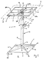
- the carrying and lifting device (1) shown in Fig. 1 essentially consists of a support surface (3) for a cladding arranged at the upper end of a telescopic support (2). or insulation board (4) having a plate holder (5), and a support foot (7) arranged at the lower end of the support (2) and displaceable on a floor surface (6) of the room.
- the support (2) consists of a vertical telescopic tube (8) with a square tube cross section, in which a telescopic rod (9) designed as a toothed rack is guided so as to be displaceable in the vertical direction.
- the rack in the telescopic tube (8) is raised and lowered via a gearwheel (11) connected to a crank (10) and rotatably mounted on an extension arm (12) of the telescopic tube (8), the teeth (13) of which through a wall opening (14 ) of the telescopic tube (8) are engaged with the teeth (15) of the telescopic rod (9).
- the gearwheel (11) is surrounded by a housing (not shown), which is connected to the telescopic tube (8) and from which a polygonal pin, which is aligned with the axis of rotation of the gearwheel (11), projects and onto which the hand crank (10) can be attached.
- the lower end of the telescopic tube (8) is inserted into a tube sleeve (16) which is arranged in the center of the support foot (7), is open at the top and closed at the bottom, and can be inserted there into a threaded bore through the wall of the tube sleeve (16) screwed-in clamping screw (17) can be clamped with the handle.
- the pipe sleeve (16) is held by four gusset plates (19), each of which leads to the corners (20) of a support frame (22) welded together from profile strips (21) with an L-shaped cross section.
- the support foot (7) carrying slide rollers (23) are arranged, each of which can be individually locked by a brake, not shown.
- the brackets (24), which connect the sliding rollers (23) to the support frame (22), are each pivotally mounted in the support frame (22) about a vertical axis.
- the plate holder (5) arranged at the upper end of the telescopic rod (9) consists essentially of a rectangular frame (26) composed of profile strips (25 a, 25 b) with an L-shaped cross-section, the side dimensions of which are chosen so that the upward facing longitudinal side surfaces (27) of the profiled strips (25 a, 25 b) of the covering or insulating panel (4) projecting over the frame (26) by 150 to 300 mm on all sides, see above that an edge strip (18) adjoining the side edges (28) of the plate (4) is accessible from below.
- the two profile strips (25a), which form the narrow sides of the frame (26), are connected by two further profile strips (29), which are arranged parallel to the profile strips (25b) forming the longitudinal sides of the frame (26) and in the middle of four Gusset plates (30) are connected to the bearing shell (31) of a ball joint (32) arranged directly below the bearing surface (3), the bearing shell (31) having 2 degrees of freedom on a ball (33) arranged at the upper end of the telescopic rod (9) is pivotable to a limited extent.
- a locking device (not shown), which can be designed, for example, as a clamping screw screwed into a threaded hole passing through the wall of the bearing shell (31), enables the plate holder (5) to be locked in different tilting positions with respect to the support (2).
- the ball (33) is arranged on the end of a square socket (34) facing the plate holder (5), which engages in a blind hole arranged at the upper end of the telescopic rod (9) and has a square cross-section and therein, similar to the telescopic tube (8) in the pipe sleeve (16) of the support leg (7) can be clamped.
- the profile strips (25a, 25b) of the frame (26) can be fitted with stop rails, not shown, which project beyond the sides of the frame (26) and which can be locked and locked from below, with upwardly bent stop plates which can be bent against the side edges (28) of the plate Be provided.
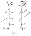
- the spacer (40) shown in Figs. 2 a and b consists essentially of a one-piece or a plurality of sections (35, 36) composed of rod (37) which has a handle (41) at one end and its handle (41) has a preferably interchangeably fastened spacer element (38) which has a thickness D corresponding to the predetermined joint thickness between the cladding or insulation panels at least in one direction transverse to the longitudinal direction of the rod (37).
- two mandrels (39) are arranged, each of which has a side edge (47) with a side face (43) of the spacer element which lies against a cladding or insulating plate (4) (38) is aligned, the tips of the mandrels (39) being directed away from the handle (41).
- the cladding or insulation panels (4) are each individually placed on the support surface (3) of the horizontally locked panel bracket (5) so that they are evenly to the sides Extend over the profile strips (25 a, 25 b) and the plate center of gravity lies on the longitudinal axis of the telescopic rod (9).
- the stops of the stop rails can be placed against the side edges (28) of the plate (4) and locked in this position, so that the plate (4) is secured against displacement on the support surface (3). Then the entire carrying and lifting device (1) with the cladding or insulation panel (4) resting on the panel holder (5) is pushed as precisely as possible under the point at which the cladding or insulation panel (4) is attached to the ceiling beams shall be.
- the castors (23) are blocked with the brakes, so that the carrying and lifting device (1) can no longer move and then extend the telescopic rod (9) by turning the hand crank (10) until the loaded one Cladding or insulation board (4) with its bearing surface facing the ceiling beams is located just below the ceiling beams. In this position, the telescopic rod (9) is locked against unintentional lowering.
- At least one spacer (40) must now be rammed into the deck beams using the spikes (39) be that one side surface (43) of the spacer element (38) abuts the side edge (28) of the already fastened plate which faces the plate (4) to be attached.
- the mandrels (39) are rammed in by placing the side edge (47) of the mandrel (39) against the side edge (28) of the already fastened plate and pushing the rod (37) upwards on the handle (41).
- the cladding or insulation panel (4) resting on the support surface (3) of the panel holder (5) can then be displaced on the support surface (3) after the stop rails have been loosened until they have their side edges (28) against the side surface (43) lie opposite side surfaces (45) of the spacer elements (38).
- the telescopic rod (9) is then extended further until the cladding or insulation panel (4) lies against it with its contact surface facing the ceiling beams.
- the gearwheel (11) with a lock (not shown)
- the cladding or insulation panel (4) resting on the support surface (3) can be screwed to the ceiling beams both in the area of the edge strip (18) and in the area between the profile strips (29) , nailed or pegged.
- the joints between them can be filled with a grout.
Landscapes
- Engineering & Computer Science (AREA)
- Architecture (AREA)
- Civil Engineering (AREA)
- Structural Engineering (AREA)
- Conveying And Assembling Of Building Elements In Situ (AREA)
Applications Claiming Priority (2)
| Application Number | Priority Date | Filing Date | Title |
|---|---|---|---|
| DE19924223225 DE4223225A1 (de) | 1992-07-15 | 1992-07-15 | Verfahren und Mittel zum Anbringen von Verkleidungs- und Dämmplatten |
| DE4223225 | 1992-07-15 |
Publications (1)
| Publication Number | Publication Date |
|---|---|
| EP0591629A1 true EP0591629A1 (fr) | 1994-04-13 |
Family
ID=6463236
Family Applications (1)
| Application Number | Title | Priority Date | Filing Date |
|---|---|---|---|
| EP93111072A Withdrawn EP0591629A1 (fr) | 1992-07-15 | 1993-07-10 | Méthode et dispositif pour le montage de panneaux de revêtement ou d'isolation |
Country Status (2)
| Country | Link |
|---|---|
| EP (1) | EP0591629A1 (fr) |
| DE (1) | DE4223225A1 (fr) |
Cited By (2)
| Publication number | Priority date | Publication date | Assignee | Title |
|---|---|---|---|---|
| US7387293B2 (en) | 2004-12-22 | 2008-06-17 | Lawrence Boucher Construction Inc. | Device for holding and positioning construction materials |
| USD592822S1 (en) | 2008-03-07 | 2009-05-19 | A. Richard Tools Co. | Device for holding and positioning construction materials |
Families Citing this family (1)
| Publication number | Priority date | Publication date | Assignee | Title |
|---|---|---|---|---|
| DE29712042U1 (de) * | 1997-07-10 | 1997-10-30 | Fitterer, Christian, 76287 Rheinstetten | Bodenbelagentfernungsmaschine |
Citations (7)
| Publication number | Priority date | Publication date | Assignee | Title |
|---|---|---|---|---|
| DE2643380A1 (de) * | 1976-09-27 | 1978-03-30 | Dieter Gein | Pneumatisches hebegeraet |
| FR2538437A1 (fr) * | 1982-12-23 | 1984-06-29 | Chatellerault Armes Cycles | Appareil pour elever et poser les plaques au plafond |
| DE8512347U1 (de) * | 1985-04-26 | 1985-06-13 | Laur, Kurt, 6800 Mannheim | Montagehilfe für Bauplatten |
| EP0163438A2 (fr) * | 1984-05-22 | 1985-12-04 | Paul Lloyd Dixon | Outil ajustable en hauteur |
| GB2162815A (en) * | 1984-08-09 | 1986-02-12 | Geoffrey Reynard | A panel support |
| DE8909821U1 (de) * | 1989-08-16 | 1989-09-28 | Debelt, Robert, 7524 Östringen | Hebevorrichtung |
| US5002446A (en) * | 1990-06-12 | 1991-03-26 | Anderson Paul C | Tool for overhead sheet installation |
-
1992
- 1992-07-15 DE DE19924223225 patent/DE4223225A1/de not_active Withdrawn
-
1993
- 1993-07-10 EP EP93111072A patent/EP0591629A1/fr not_active Withdrawn
Patent Citations (7)
| Publication number | Priority date | Publication date | Assignee | Title |
|---|---|---|---|---|
| DE2643380A1 (de) * | 1976-09-27 | 1978-03-30 | Dieter Gein | Pneumatisches hebegeraet |
| FR2538437A1 (fr) * | 1982-12-23 | 1984-06-29 | Chatellerault Armes Cycles | Appareil pour elever et poser les plaques au plafond |
| EP0163438A2 (fr) * | 1984-05-22 | 1985-12-04 | Paul Lloyd Dixon | Outil ajustable en hauteur |
| GB2162815A (en) * | 1984-08-09 | 1986-02-12 | Geoffrey Reynard | A panel support |
| DE8512347U1 (de) * | 1985-04-26 | 1985-06-13 | Laur, Kurt, 6800 Mannheim | Montagehilfe für Bauplatten |
| DE8909821U1 (de) * | 1989-08-16 | 1989-09-28 | Debelt, Robert, 7524 Östringen | Hebevorrichtung |
| US5002446A (en) * | 1990-06-12 | 1991-03-26 | Anderson Paul C | Tool for overhead sheet installation |
Cited By (2)
| Publication number | Priority date | Publication date | Assignee | Title |
|---|---|---|---|---|
| US7387293B2 (en) | 2004-12-22 | 2008-06-17 | Lawrence Boucher Construction Inc. | Device for holding and positioning construction materials |
| USD592822S1 (en) | 2008-03-07 | 2009-05-19 | A. Richard Tools Co. | Device for holding and positioning construction materials |
Also Published As
| Publication number | Publication date |
|---|---|
| DE4223225A1 (de) | 1994-01-20 |
Similar Documents
| Publication | Publication Date | Title |
|---|---|---|
| DE2741601A1 (de) | Transportables oder verstellbares wandsystem | |
| DE3004245C2 (de) | Deckenschalung mit Fallköpfen | |
| DE102016012946A1 (de) | Vorrichtung zur Erleichterung der Anbringung von Hilfsmitteln zur Herstellung einer oberen Begrenzung einer Wandöffnung im Bauwesen | |
| DE3036306A1 (de) | Verfahren zum zusammenbau und ausschalen von deckenschalungen fuer betonierarbeiten sowie deckenschalungen zur durchfuehrung des verfahrens | |
| DE4445403B4 (de) | Kabelgestell und Kabelgestellhalter | |
| DE29514636U1 (de) | Raumhohe Absperrvorrichtung | |
| DE4223225A1 (de) | Verfahren und Mittel zum Anbringen von Verkleidungs- und Dämmplatten | |
| DE19508682C2 (de) | Vorrichtung zur lösbaren Verbindung von auf Stoß aneinandergelegten Fußbodenplatten eines demontierbaren Sport- oder Mehrzweckhallenbodens | |
| DE3709441A1 (de) | Auf dem dach eines gedeckten gebaeudes abstuetzbares kamingeruest | |
| DE102016111211B4 (de) | Schalungssystem für die Errichtung niedriger Bauabschnitte aus Ortbeton | |
| DE19828037A1 (de) | Hilfsvorrichtung für die Befestigung von Gipskartonplatten | |
| DE3641985A1 (de) | Verfahren zum verlegen oder austauschen von platten an fassaden | |
| DE3324301C2 (fr) | ||
| EP1373659B1 (fr) | Dispositif auxiliaire de montage permettant la fixation d'une sous-structure destinee a recevoir des revetements muraux ou de toiture | |
| DE10035823A1 (de) | Schalungsträger | |
| DE29705696U1 (de) | Vorrichtung zur Vereinfachung der Ein- und Ausschalung von Deckenflächen im Hoch- und Tiefbau | |
| DE8623761U1 (de) | Mauerlehre | |
| EP0674065A1 (fr) | Dispositif pour mettre en place et pour niveler les supports de planchers à doubles fonds surélevés | |
| DE29922223U1 (de) | Montagewagen | |
| DE10017564A1 (de) | Vorrichtung zur Positionierung von Stützen zur Aufnahme von Bodenplatten für einen doppelten Boden | |
| EP0666380B1 (fr) | Dispositif pour la fixation de poteaux de balcon | |
| EP3848321A2 (fr) | Système de barrière transportable permettant de fermer les ouvertures de cage d'ascenseur pendant la phase de construction et de créer des zones de magasinage temporairement requises dans les nouveaux bâtiments | |
| DE4442367C1 (de) | Verlegevorrichtung für Gipsausbauplatten | |
| WO1998009039A1 (fr) | Dispositif pour la pose des plaques de plafond | |
| DE20303233U1 (de) | Wandelement |
Legal Events
| Date | Code | Title | Description |
|---|---|---|---|
| PUAI | Public reference made under article 153(3) epc to a published international application that has entered the european phase |
Free format text: ORIGINAL CODE: 0009012 |
|
| AK | Designated contracting states |
Kind code of ref document: A1 Designated state(s): AT BE ES FR IT NL |
|
| STAA | Information on the status of an ep patent application or granted ep patent |
Free format text: STATUS: THE APPLICATION IS DEEMED TO BE WITHDRAWN |
|
| 18D | Application deemed to be withdrawn |
Effective date: 19941014 |