EP0591634A1 - Dispositif de nettoyage pour cylindre de machine à imprimer - Google Patents
Dispositif de nettoyage pour cylindre de machine à imprimer Download PDFInfo
- Publication number
- EP0591634A1 EP0591634A1 EP93111383A EP93111383A EP0591634A1 EP 0591634 A1 EP0591634 A1 EP 0591634A1 EP 93111383 A EP93111383 A EP 93111383A EP 93111383 A EP93111383 A EP 93111383A EP 0591634 A1 EP0591634 A1 EP 0591634A1
- Authority
- EP
- European Patent Office
- Prior art keywords
- washing
- bar
- cylinder
- wash
- suspension device
- Prior art date
- Legal status (The legal status is an assumption and is not a legal conclusion. Google has not performed a legal analysis and makes no representation as to the accuracy of the status listed.)
- Granted
Links
- 238000007639 printing Methods 0.000 title claims abstract description 40
- 238000004140 cleaning Methods 0.000 title abstract 2
- 238000005406 washing Methods 0.000 claims abstract description 131
- 239000000725 suspension Substances 0.000 claims abstract description 41
- 239000007788 liquid Substances 0.000 claims abstract description 12
- 239000004744 fabric Substances 0.000 claims description 24
- 239000007921 spray Substances 0.000 claims description 5
- 230000008878 coupling Effects 0.000 claims description 4
- 238000010168 coupling process Methods 0.000 claims description 4
- 238000005859 coupling reaction Methods 0.000 claims description 4
- 239000012530 fluid Substances 0.000 claims description 2
- 230000008676 import Effects 0.000 claims 1
- 238000005507 spraying Methods 0.000 claims 1
- 238000006073 displacement reaction Methods 0.000 abstract 1
- 230000037431 insertion Effects 0.000 description 2
- 238000003780 insertion Methods 0.000 description 2
- 239000002904 solvent Substances 0.000 description 2
- XLYOFNOQVPJJNP-UHFFFAOYSA-N water Substances O XLYOFNOQVPJJNP-UHFFFAOYSA-N 0.000 description 2
- 239000003795 chemical substances by application Substances 0.000 description 1
- 239000003599 detergent Substances 0.000 description 1
- 238000007645 offset printing Methods 0.000 description 1
Images



Classifications
-
- B—PERFORMING OPERATIONS; TRANSPORTING
- B41—PRINTING; LINING MACHINES; TYPEWRITERS; STAMPS
- B41F—PRINTING MACHINES OR PRESSES
- B41F35/00—Cleaning arrangements or devices
Definitions
- the invention relates to a printing press cylinder washing device for washing at least one cylinder in the printing unit of a printing press.
- the printing press cylinder washing device is particularly suitable for offset printing presses.
- washing bar From practice it is known to insert a washing bar from a cylinder end into a washing device and to connect it to a connection unit via which washing liquid, for example water or liquid washing agent or solvent or compressed air, is fed to the washing bar. Furthermore, washing devices are known from DE 30 05 469 C2, DE 28 15 388 C3 and EP 0 334 173 A1, in which the washing bar can be adjusted between a washing position approximating the cylinder to be cleaned and a basic position distant therefrom.
- washing liquid for example water or liquid washing agent or solvent or compressed air
- the wash bar must in particular be inserted into the printing unit from one end of the printing unit cylinder when there is no space for the washing device at the top and on the side of the cylinder and the washing bar must be arranged below the lower half of the cylinder. Access to the lower half of the cylinder is often only possible through a relatively small opening in one of the machine side stands.
- the narrow space conditions not only make it possible to insert the washing bar into the washing device, but also to connect the washing bar to the supply lines for washing liquid and / or compressed air.
- the compressed air can be used to press a washcloth onto the cylinder to be cleaned and / or to actuate pneumatic drives of the washing device.
- the soiled washcloth must often be removed from the washbar, for example once a week, and replaced with a clean washcloth. To do this, due to the limited space available, the wash bars must be removed from the printing unit and then used again.
- the washing device contains a washing bar 6 with a washing cloth 8, which is wound on the washing bar 6 by a clean cloth spindle 10 onto a dirty cloth spindle 11 and has a cloth section 12 opposite the cylinder 2 with a small distance of less than 10 mm.
- This wash cloth section 12 can be applied to the cylinder surface 15 by a pressure element 14 of the wash bar 6.
- the pressing element 14 is preferably a hose that can be expanded by compressed air.
- the washcloth section 12 can be applied directly to the cylinder 2 through the washing bar 6, without the interposition of an expandable pressing element 14.
- the washing bar 6 is provided with a spray device 17, through which washing liquid, for example water or liquid detergent or solvent, is sprayed onto the rear side of the washing cloth section 12 facing away from the cylinder 2.
- the washing bar 6 is carried by a suspension device 20, by means of which the washing bar 6 can be displaced between the washing position shown in FIG. 1, approximating the surface of the cylinder 2, and a starting position further away from the cylinder surface.
- the starting position of the washing bar 6 is shown in broken lines in FIG. 1. In this starting position, the washing bar 6 is located behind an opening 22 of the side frame 3 within the height dimensions of this opening 22.
- Connection means 28 are provided on the washing bar 6, of which a hose 29 for supplying washing liquid to the spray device 17 and a further hose 30 for supplying compressed air into the pressing element 14 leads to its expansion.
- the spray device 17 can spray washing liquid onto the cylinder 2 or onto the cylinder 2 and onto the washing cloth 8.
- the linear guide device 24 consists of a first guide body 32 fastened to the suspension device 20 and of a second guide body 33 provided on the washing bar 6.
- the two guide bodies 32 and 33 form a plug connection running in the longitudinal direction of the washing bar, which holds the washing bar 6 on the suspension device 20, but the Retracting and extending movement of the washing bar 6 in the longitudinal direction of the washing bar is permitted when the washing bar 6 is in the dot-dash starting position in FIG. 1.
- connection unit 36 and the connection means 28 of the wash bar 6 are opposite one another in the wash bar longitudinal direction 25 arranged in such a way that the connecting means 28 of the washing bar 6 are moved towards the connecting unit 36 of the hanging device 20 and are automatically coupled to it when the washing bar 6 is moved into the hanging device 20 in the starting position 6 '.
- other energies for example hydraulic fluid or electric current, can also be transmitted through the connection unit 38 and through the connection means 28 automatically coupled to them.
- a drive 40 for preferably gradually rotating the dirty cloth spindle 11 is fastened.
- the drive 40 is connected via a plug-in coupling to the dirty cloth spindle 11, the two coupling parts 41 and 42 of which lie opposite one another in the longitudinal direction 25 of the washing bar and are automatically coupled or uncoupled to one another when the washing bar 6 is plugged onto the suspension device 20 in the longitudinal direction 25 of the washing bar or is subtracted from this.
- connection means 28 against the connection unit 38 is achieved in a simple manner in that the locking slot 46 has a cam surface 47 directed obliquely to the connection unit 36.
- spring means 48 are arranged between the wash bar 6 or the second guide body 33 and the arm 34 of the first guide body 32, which counteract the insertion movement of the wash bar 6.
- the suspension device 20 is mounted on the two printing press side stands 3 and 4 so as to be pivotable by bearings 50 about a pivot axis A which runs parallel to the axis of rotation D of the cylinder 2.
- two pneumatic cylinders 52 and 53 are provided, the cylinder housings 54 of which are pivotally attached to a machine cross member 55 about a pivot axis B, which runs parallel to the other two axes A and D.
- the piston rods 56 of the two compressed air cylinders 52 and 53 are connected to the first guide body 32 of the suspension device 20 so as to be pivotable about pivot axes C.
- the pivot axes C are parallel to that Pivot axis A and the rotational axis D.
- the two pivot axes C are aligned with one another.
- the two pivot axes B are also aligned with one another.
- the two compressed air cylinders 52 and 53 are arranged at a distance from one another in the longitudinal direction of the washing bar.
- the two compressed air cylinders 52 and 53 can pivot the suspension device 20 with the washing bar 6 fastened thereon on an arcuate movement path around the pivot axis A between the washing position shown in solid lines at the top in FIG. 1 and the starting position shown in dash-dotted lines below.
- the compressed air cylinders 52 and 53 are preferably reciprocally pressurized units.
- FIGS. 2 to 6 parts corresponding to FIG. 1 are provided with the same reference numbers.
- the pivot axis A of the suspension device is replaced by four pivot axes A1, A2, A3 and A4, which together form a parallelogram or trapezoidal joint.
- the pivot axes A1, A2, A3 and A4 run parallel to one another and parallel to the axis of rotation D of the cylinder 2.
- the two pivot axes A1 and A2 are formed by bearings on the machine crossmember 55.
- the pivot axes A3 and A4 are formed by bearings in a bearing block 60 of the suspension device 20, to which the first guide body 32 of the linear guide device 24 is attached.
- the drive 40 for the dirty cloth spindle 11 is a compressed air cylinder which is pivotally mounted on the first guide body 32, which is carried by the suspension device 20, via a pivot axis F, which runs parallel to the axis of rotation D of the cylinder 2.
- the piston 66 of the compressed air cylinder 40 is drivingly connected to the dirty cloth spindle 11 via a joint with a pivot axis G and a lever 67 via the coupling 41, 42 of FIG. 1. 3, the clean cloth spindle 10 and the dirty cloth spindle 11 are mounted in side plates 70 and 71 of the washing bar 6, which are fastened on the base plate 62.
- a cloth end indicator 74 attached to the machine side stand 4 then generates a signal by which the washing device and the printing unit are switched off, when the end of the washcloth is almost reached, but also when the wash bar 6 is not in the washing position shown in FIGS. 1, 2 and 3.
- the cloth end indicator 74 thus simultaneously fulfills a safety function.
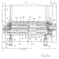
- FIG. 6 shows the first guide body 32 of the suspension device 20 with the base plate 62 and its guide segments 63 and 64 in the washing position and, denoted by 32 ′, 62 ′ and 64 ′, in its starting position underneath.
- a second linear guide device 76 adjoins the front end of the linear guide device 24 facing away from the connection unit 36, which extends under a tread plate 78 of the printing unit and subsequently guides the wash bar 6 to the first linear guide means 24 in the longitudinal direction 25 of the wash bar 6.
- the second linear guide device 76 is configured with respect to the individual guide elements 62, 63, 64 and 65 in the same way as the first linear guide device 24.
- the second linear guide device 76 is located at the height of the first linear guide device 24 when the latter is in the downwardly pivoted starting position, such as this shows Fig. 6.
- the washing bar 6 on the side 80 of the tread plate 78 facing away from the cylinder 2 can pass through the machine opening 82 underneath and onto the second linear guide device 76 inserted and guided in the longitudinal direction 25 of the washing bar under the step plate 78 and then transferred to the first linear guide device 24 while it is in its starting position.
- the washing bar 6 with the washing cloth 8 can be guided from the first linear guide device 24 in its starting position in the longitudinal direction 25 of the washing bar to the second linear guide device 76 and removed therefrom under the tread plate 78, for example in order to replace the washing cloth 8.
- the second linear guide device 76 stands on the machine floor 84.
- the wash bar located on the second linear guide device 76 in FIG. 6 is identified there by 6 ′′ and its washcloth by 8 ′′.
Landscapes
- Inking, Control Or Cleaning Of Printing Machines (AREA)
Applications Claiming Priority (2)
| Application Number | Priority Date | Filing Date | Title |
|---|---|---|---|
| DE4233953A DE4233953A1 (de) | 1992-10-08 | 1992-10-08 | Druckmaschinenzylinder-Waschvorrichtung |
| DE4233953 | 1992-10-08 |
Publications (2)
| Publication Number | Publication Date |
|---|---|
| EP0591634A1 true EP0591634A1 (fr) | 1994-04-13 |
| EP0591634B1 EP0591634B1 (fr) | 1996-04-24 |
Family
ID=6470002
Family Applications (1)
| Application Number | Title | Priority Date | Filing Date |
|---|---|---|---|
| EP93111383A Expired - Lifetime EP0591634B1 (fr) | 1992-10-08 | 1993-07-15 | Dispositif de nettoyage pour cylindre de machine à imprimer |
Country Status (2)
| Country | Link |
|---|---|
| EP (1) | EP0591634B1 (fr) |
| DE (2) | DE4233953A1 (fr) |
Cited By (4)
| Publication number | Priority date | Publication date | Assignee | Title |
|---|---|---|---|---|
| DE19506640A1 (de) * | 1995-02-25 | 1996-08-29 | Roland Man Druckmasch | Einrichtung zum Reinigen von Zylindern in Druckmaschinen |
| DE19860855A1 (de) * | 1998-12-31 | 2000-07-06 | Koenig & Bauer Ag | Vorrichtung zum Reinigen einer Walze |
| DE10000554A1 (de) * | 2000-01-08 | 2001-07-12 | Baldwin Grafotec Gmbh | Waschanlage für Druckmaschinenzylinder |
| US7506585B2 (en) | 2005-04-20 | 2009-03-24 | Heidelberger Druckmaschinen Ag | Method of operating a press |
Families Citing this family (6)
| Publication number | Priority date | Publication date | Assignee | Title |
|---|---|---|---|---|
| DE19609737C1 (de) | 1996-03-13 | 1997-05-07 | Roland Man Druckmasch | Vorrichtung zum lösbaren Verbinden von Versorgungsleitungen in einer Druckmaschine |
| DE10040950B4 (de) * | 1999-09-15 | 2009-04-02 | Heidelberger Druckmaschinen Ag | Druckmaschine |
| DE10044861B4 (de) * | 1999-09-29 | 2010-09-02 | Heidelberger Druckmaschinen Ag | Wickelverfahren und -vorrichtung für bedruckstoffverarbeitende Maschinen |
| DE10206810A1 (de) * | 2002-02-19 | 2003-08-28 | Baldwin Germany Gmbh | Waschvorrichtung für Druckmaschinenzylinder |
| DE102007047391A1 (de) * | 2007-10-04 | 2009-04-16 | Technotrans Ag | Fluidandockung in achsparalleler Zylinderrichtung |
| DE102009058744B4 (de) | 2009-12-17 | 2012-11-29 | Technotrans Ag | Reinigungsvorrichtung für Druck- und Druckplattenzylinder |
Citations (3)
| Publication number | Priority date | Publication date | Assignee | Title |
|---|---|---|---|---|
| EP0243712A2 (fr) * | 1986-04-29 | 1987-11-04 | Heidelberger Druckmaschinen Aktiengesellschaft | Dispositif de nettoyage pour cylindres d'impression de machines à imprimer |
| EP0243706A2 (fr) * | 1986-04-29 | 1987-11-04 | M.A.N.-ROLAND Druckmaschinen Aktiengesellschaft | Système de nettoyage de cylindres dans les machines rotatives |
| EP0364901A2 (fr) * | 1988-10-19 | 1990-04-25 | Dai Nippon Insatsu Kabushiki Kaisha | Système de nettoyage pour presses d'impression offset à feuilles |
-
1992
- 1992-10-08 DE DE4233953A patent/DE4233953A1/de not_active Withdrawn
-
1993
- 1993-07-15 DE DE59302344T patent/DE59302344D1/de not_active Expired - Lifetime
- 1993-07-15 EP EP93111383A patent/EP0591634B1/fr not_active Expired - Lifetime
Patent Citations (3)
| Publication number | Priority date | Publication date | Assignee | Title |
|---|---|---|---|---|
| EP0243712A2 (fr) * | 1986-04-29 | 1987-11-04 | Heidelberger Druckmaschinen Aktiengesellschaft | Dispositif de nettoyage pour cylindres d'impression de machines à imprimer |
| EP0243706A2 (fr) * | 1986-04-29 | 1987-11-04 | M.A.N.-ROLAND Druckmaschinen Aktiengesellschaft | Système de nettoyage de cylindres dans les machines rotatives |
| EP0364901A2 (fr) * | 1988-10-19 | 1990-04-25 | Dai Nippon Insatsu Kabushiki Kaisha | Système de nettoyage pour presses d'impression offset à feuilles |
Cited By (8)
| Publication number | Priority date | Publication date | Assignee | Title |
|---|---|---|---|---|
| DE19506640A1 (de) * | 1995-02-25 | 1996-08-29 | Roland Man Druckmasch | Einrichtung zum Reinigen von Zylindern in Druckmaschinen |
| EP0728582A3 (fr) * | 1995-02-25 | 1996-11-20 | Roland Man Druckmasch | Dispositif pour nettoyer des cylindres de machines à imprimer |
| US5615612A (en) * | 1995-02-25 | 1997-04-01 | Man Roland Druckmaschinen Ag | Apparatus for the cleaning of cylinders of a printing machine |
| DE19506640C2 (de) * | 1995-02-25 | 1998-09-10 | Roland Man Druckmasch | Einrichtung zum Reinigen von Zylindern in Druckmaschinen |
| DE19860855A1 (de) * | 1998-12-31 | 2000-07-06 | Koenig & Bauer Ag | Vorrichtung zum Reinigen einer Walze |
| US6601510B1 (en) | 1998-12-31 | 2003-08-05 | Koenig & Bauer Aktiengesellschaft | Devices for cleaning a roller |
| DE10000554A1 (de) * | 2000-01-08 | 2001-07-12 | Baldwin Grafotec Gmbh | Waschanlage für Druckmaschinenzylinder |
| US7506585B2 (en) | 2005-04-20 | 2009-03-24 | Heidelberger Druckmaschinen Ag | Method of operating a press |
Also Published As
| Publication number | Publication date |
|---|---|
| DE59302344D1 (de) | 1996-05-30 |
| EP0591634B1 (fr) | 1996-04-24 |
| DE4233953A1 (de) | 1994-04-14 |
Similar Documents
| Publication | Publication Date | Title |
|---|---|---|
| DE2815388B2 (de) | Vorrichtung zum Waschen von Zylindern an Druckmaschinen, insbesondere Offsetdruckmaschinen | |
| EP0562281A1 (fr) | Dispositif pour nettoyer plusieurs cylindres alternativement | |
| EP0591634B1 (fr) | Dispositif de nettoyage pour cylindre de machine à imprimer | |
| DE4215355C2 (de) | Waschvorrichtung für Zylinder in Druckmaschinen, insbesondere Bogenoffsetdruckmaschinen | |
| DE3735302C2 (fr) | ||
| EP3249124A1 (fr) | Véhicule comprenant un dispositif de nettoyage de canal | |
| DE19958087A1 (de) | Verfahren zur Entnahme und zum Einsetzen einer Reinigungseinrichtung sowie Druckmaschine, insbesondere zur Durchführung des Verfahrens | |
| EP0287822B1 (fr) | Dispositif pour enlever des particules étrangères du cylindre porte-plaque d'une machine à imprimer offset | |
| DE19506640C2 (de) | Einrichtung zum Reinigen von Zylindern in Druckmaschinen | |
| DE9213605U1 (de) | Druckmaschinenzylinder-Waschvorrichtung | |
| EP0369269B1 (fr) | Dispositif d'entrée ou de sortie de produits laminés, en particulier de profilés, entre les cylindres de cages de laminoir | |
| DE19609737C1 (de) | Vorrichtung zum lösbaren Verbinden von Versorgungsleitungen in einer Druckmaschine | |
| EP1023996A2 (fr) | Système de lavage à l'extérieur d'une machine d'impression pour blanchets en caoutchouc en forme de boites | |
| EP1151864B1 (fr) | Dispositif pour nettoyer un cylindre d'une machine à imprimer | |
| EP0606581A1 (fr) | Dispositif de nettoyage automatique des cylindres de blanchet d'une rotative à rouleaux | |
| DE69912076T2 (de) | Schrägwalzwerk | |
| DE4221026C2 (de) | Vorrichtung zum Reinigen von Zylindern in einer Rotationsdruckmaschine | |
| DE4326833A1 (de) | Druckmaschinenzylinder-Waschvorrichtung | |
| DE19860855A1 (de) | Vorrichtung zum Reinigen einer Walze | |
| DE20012140U1 (de) | Vorrichtung zum Herausziehen und Reinigen von Schaberklingen | |
| DE9212882U1 (de) | Druckmaschinenzylinder-Waschvorrichtung | |
| EP1244552A2 (fr) | Dispositif de nettoyage pour cylindre de machine a imprimer | |
| DE4203914A1 (de) | Vorrichtung zum reinigen eines druckzylinders in einer druckmaschine | |
| EP2141284B1 (fr) | Dispositif de retenue de lame de racloir | |
| DE19512421C2 (de) | Einrichtung zum Reinigen mehrerer Zylinder |
Legal Events
| Date | Code | Title | Description |
|---|---|---|---|
| PUAI | Public reference made under article 153(3) epc to a published international application that has entered the european phase |
Free format text: ORIGINAL CODE: 0009012 |
|
| 17P | Request for examination filed |
Effective date: 19930715 |
|
| AK | Designated contracting states |
Kind code of ref document: A1 Designated state(s): CH DE FR GB IT LI SE |
|
| 17Q | First examination report despatched |
Effective date: 19950824 |
|
| GRAH | Despatch of communication of intention to grant a patent |
Free format text: ORIGINAL CODE: EPIDOS IGRA |
|
| GRAA | (expected) grant |
Free format text: ORIGINAL CODE: 0009210 |
|
| AK | Designated contracting states |
Kind code of ref document: B1 Designated state(s): CH DE FR GB IT LI SE |
|
| ET | Fr: translation filed | ||
| GBT | Gb: translation of ep patent filed (gb section 77(6)(a)/1977) |
Effective date: 19960429 |
|
| REF | Corresponds to: |
Ref document number: 59302344 Country of ref document: DE Date of ref document: 19960530 |
|
| ITF | It: translation for a ep patent filed | ||
| PG25 | Lapsed in a contracting state [announced via postgrant information from national office to epo] |
Ref country code: LI Effective date: 19960731 Ref country code: CH Effective date: 19960731 |
|
| PLBE | No opposition filed within time limit |
Free format text: ORIGINAL CODE: 0009261 |
|
| STAA | Information on the status of an ep patent application or granted ep patent |
Free format text: STATUS: NO OPPOSITION FILED WITHIN TIME LIMIT |
|
| REG | Reference to a national code |
Ref country code: CH Ref legal event code: PL |
|
| 26N | No opposition filed | ||
| REG | Reference to a national code |
Ref country code: GB Ref legal event code: IF02 |
|
| PGFP | Annual fee paid to national office [announced via postgrant information from national office to epo] |
Ref country code: GB Payment date: 20030624 Year of fee payment: 11 |
|
| PGFP | Annual fee paid to national office [announced via postgrant information from national office to epo] |
Ref country code: FR Payment date: 20030721 Year of fee payment: 11 |
|
| PGFP | Annual fee paid to national office [announced via postgrant information from national office to epo] |
Ref country code: SE Payment date: 20030728 Year of fee payment: 11 |
|
| PG25 | Lapsed in a contracting state [announced via postgrant information from national office to epo] |
Ref country code: GB Free format text: LAPSE BECAUSE OF NON-PAYMENT OF DUE FEES Effective date: 20040715 |
|
| PG25 | Lapsed in a contracting state [announced via postgrant information from national office to epo] |
Ref country code: SE Free format text: LAPSE BECAUSE OF NON-PAYMENT OF DUE FEES Effective date: 20040716 |
|
| EUG | Se: european patent has lapsed | ||
| GBPC | Gb: european patent ceased through non-payment of renewal fee |
Effective date: 20040715 |
|
| PG25 | Lapsed in a contracting state [announced via postgrant information from national office to epo] |
Ref country code: FR Free format text: LAPSE BECAUSE OF NON-PAYMENT OF DUE FEES Effective date: 20050331 |
|
| REG | Reference to a national code |
Ref country code: FR Ref legal event code: ST |
|
| PGFP | Annual fee paid to national office [announced via postgrant information from national office to epo] |
Ref country code: DE Payment date: 20110804 Year of fee payment: 19 |
|
| PGFP | Annual fee paid to national office [announced via postgrant information from national office to epo] |
Ref country code: IT Payment date: 20110726 Year of fee payment: 19 |
|
| PG25 | Lapsed in a contracting state [announced via postgrant information from national office to epo] |
Ref country code: DE Free format text: LAPSE BECAUSE OF NON-PAYMENT OF DUE FEES Effective date: 20130201 |
|
| REG | Reference to a national code |
Ref country code: DE Ref legal event code: R119 Ref document number: 59302344 Country of ref document: DE Effective date: 20130201 |
|
| PG25 | Lapsed in a contracting state [announced via postgrant information from national office to epo] |
Ref country code: IT Free format text: LAPSE BECAUSE OF NON-PAYMENT OF DUE FEES Effective date: 20120715 |