EP0591639A2 - Gasdichtemesser - Google Patents
Gasdichtemesser Download PDFInfo
- Publication number
- EP0591639A2 EP0591639A2 EP93112322A EP93112322A EP0591639A2 EP 0591639 A2 EP0591639 A2 EP 0591639A2 EP 93112322 A EP93112322 A EP 93112322A EP 93112322 A EP93112322 A EP 93112322A EP 0591639 A2 EP0591639 A2 EP 0591639A2
- Authority
- EP
- European Patent Office
- Prior art keywords
- pressure
- chamber
- gas
- sample gas
- flowing
- Prior art date
- Legal status (The legal status is an assumption and is not a legal conclusion. Google has not performed a legal analysis and makes no representation as to the accuracy of the status listed.)
- Ceased
Links
Images


Classifications
-
- G—PHYSICS
- G01—MEASURING; TESTING
- G01F—MEASURING VOLUME, VOLUME FLOW, MASS FLOW OR LIQUID LEVEL; METERING BY VOLUME
- G01F15/00—Details of, or accessories for, apparatus of groups G01F1/00 - G01F13/00 insofar as such details or appliances are not adapted to particular types of such apparatus
- G01F15/02—Compensating or correcting for variations in pressure, density or temperature
- G01F15/04—Compensating or correcting for variations in pressure, density or temperature of gases to be measured
- G01F15/043—Compensating or correcting for variations in pressure, density or temperature of gases to be measured using electrical means
- G01F15/046—Compensating or correcting for variations in pressure, density or temperature of gases to be measured using electrical means involving digital counting
-
- G—PHYSICS
- G01—MEASURING; TESTING
- G01N—INVESTIGATING OR ANALYSING MATERIALS BY DETERMINING THEIR CHEMICAL OR PHYSICAL PROPERTIES
- G01N7/00—Analysing materials by measuring the pressure or volume of a gas or vapour
Definitions
- the present invention relates to a method and instrumentation that measures, in real time, the density of a gas flowing in a pipeline.
- the invention can also measure a base condition density of the same gas where the base condition density corresponds to a density (i.e. mass/volume) of the gas determined as if the gas were at some defined base temperature and pressure condition.
- the present invention determines a ratio of the measured flowing condition density compared to the base condition density. This ratio can be referred to as a volume correction ratio and can be used to translate a measured pipeline gas volumetric flowrate to a corresponding base condition volumetric flow rate.
- volumetric flowmeters e.g., an orifice plate meter
- the density term appears directly in the volume flow equation (i.e. ⁇ P).
- the translation of volumetric flowrate to base conditions i.e. volume correction ratio
- Gas densities, volume correction ratios, and volumetric flowrates at base conditions are normally calculated using flow computers from contemporaneous measurements of several gas parameters.
- the pipeline gas volumetric flowrate at pipeline conditions is measured, the gas temperature and pressure at pipeline conditions are measured, and the composition of the gas is measured. Gas composition is normally measured by a chromatograph. From this measured data, gas supercompressibility at both pipeline and base conditions is calculated and from that the density of the gas at pipeline and base conditions is calculated.
- gas supercompressibility is usually estimated from either virial equations of state or from correlations such as NX-19.
- virial coefficients is severely limited because the virial coefficients are functions of temperature, pressure, and composition, are largely unknown, and have significant real time uncertainties. Also, using correlations such as NX-19 is often inaccurate because the correlations can be inaccurate for many compositions.
- the Gerg Equations estimate supercompressibility and density from knowledge of the heating value, the density of the gas at base conditions and the percentage of carbon dioxide and nitrogen in the exhaust of burned gas. Such measurements can be made using PMI's GB 3000 product (Precision Measurements, Inc., Tulsa, Oklahoma).
- the Gerg Equations allow more rapid computation of supercompressibility than the above described composition methods and are, therefore, preferred in applications at normal natural gas pipeline pressures.
- extensive use of a flow computer is required to solve the Gerg Equations.
- each of the measurements recited above in describing both the composition method or the Gerg Equations method introduce the potential for measurement error.
- the aggregation of such errors can substantially influence accuracy. Because of this, it is common practice to frequently calibrate and maintain each individual measurement device.
- inventions are disclosed that among other things can determine the volume correction ratio of a pipeline gas from energy type measurements. These inventions involve the measurement of energy flowrate and energy content of a sample of gas tapped from the pipeline. A base condition volumetric flowrate of the sample gas can then be determined by the ratio of the energy flowrate of the sample gas to the energy content of the sample gas. These inventions also measure the ratio of the mass flowrate of the pipeline gas in the pipeline compared to the mass flowrate of the sample gas tapped from the pipeline. The volume correction ratio (or the base condition volumetric flowrate of the pipeline gas) can be calculated easily from the mass flowrate ratio and the base condition volumetric flowrate of the sample gas.
- the object of the present invention is to provide an improved method and apparatus for measuring a volume correction ratio and a flowing condition density of a pipeline gas.
- Another object of the present invention is to make these measurements without making energy type measurements.
- the present invention is a method and apparatus that can determine a volume correction ratio for a gas (i.e. a ratio of a flowing condition density compared to a base condition density and in another aspect can also determine a flowing condition density of a gas. It can make these determinations accurately in real time, without making several highly variable measurements, without making any energy type measurements, and without making excessive numeric calculations or correlations in a flow computer.
- the present invention measures the volume correction ratio by measuring the temperature and pressure of sample gas tapped from a pipeline as it undergoes controlled expansion. Before the expansion, the sample gas is trapped to assure that it has the same composition as the pipeline gas.
- the rate of expansion of the trapped sample gas can be controlled in several ways, but it is preferred that the expansion be controlled by establishing mass flow at sonic conditions through a sonic nozzle. It is important that the expansion of the sample gas occur while the trapped sample gas is at substantially the same temperature as the pipeline gas being monitored. In a preferred embodiment, this is achieved by immersing a portion of the meter within the pipeline.
- sample gas is tapped from the pipeline and flows to a first chamber having a fixed volume.
- a first valve controls the flow of sample gas into the first chamber. When the first valve is opened, sample gas flows into the first chamber preferably until the pressure in the first chamber equals the pressure in the pipeline.
- the first valve is then closed and stops further pipeline gas from flowing into the first chamber.
- the sample gas temperature In order to measure the volume correction ratio, the sample gas temperature must be maintained at substantially the same temperature as the pipeline gas temperature.
- Sample gas flows from the first chamber and then through a flow restrictor located downstream of the first chamber.
- the flow restrictor is preferably a sonic nozzle.
- the sample gas pressure at the inlet of the flow restrictor is established by a pressure regulator so that gas flows from the first chamber at a substantially constant flowrate.
- the established pressure is sufficient so that the mass flow through the sonic nozzle is critical (i.e., the sonic nozzle inlet pressure is sufficient so that the mass flowrate through the sonic nozzle is proportional to the density and sonic velocity of the gas and nozzle cross-sectional area).
- Flowing sample gas from the first chamber when the first valve is closed causes the pressure in the first chamber to reduce over time.
- the rate of change of the pressure in the first chamber is measured as the pressure in the first chamber decays.
- the temperature of pipeline gas being monitored is also measured.
- the volume correction ratio is determined from the rate of change of pressure in the first chamber, the absolute pressure of the pipeline gas, and the absolute temperature of the pipeline gas. The determination can be done without resorting to estimates and approximations for supercompressibility.
- the present invention eliminates the need to estimate or consider the effects of supercompressibility when determining gas density because the pressure rate of change measurements in the first chamber are made and used in density calculations directly.
- the volume correction ratio (i.e. the ratio of the flowing condition density p f to the base condition density p b ) is used to determine the flowing condition density p f from a measured base condition density p b .
- the preferred method and apparatus for measuring the base condition density p b are disclosed generally in U.S. Patent No. 4,677,841 to Kennedy, et al. It is preferred that the sonic nozzle of the present invention for measuring the volume correction ratio also be used as a pore where the square of the mass flow rate through the pore is inversely proportional to the density of gas flowing through the pore when the present invention measures the base condition density Pb.
- the first valve be maintained open to allow sample gas to flow into the first chamber and therefrom; through the pressure regulator; and then into a second chamber also having a fixed volume. Also preferably, the flow into the second chamber is controlled by a second valve. The flow of sample gas from the second chamber is restricted by the pore. The mass flowrate through the pore is measured and from that mass flowrate measurement and a similar measurement of a reference gas which is made periodically, the base condition density p b of the sample gas can be determined.
- volumetric flow signals are received from a volumetric flowmeter in the pipeline and the volumetric and mass flowrate in the pipeline at base conditions or pipeline conditions can be determined.
- the aspect of the invention that measures the base condition density p b (i.e., U.S. Patent No. 4,677,841 in conjunction with a reference gas) has proven to be accurate. Also, using a reference gas avoids the need to force the sample gas temperature and pressure to base conditions at the pore, such as 14.71 psia and 60 ° F, in order to make a base condition density p b measurement. This is because the density of the gas flowing through the pore is measured at ambient conditions and then translated to the base condition density through a prior knowledge of the reference gas base condition.
- the present invention includes many aspects, including the aspect of measuring a volume correction ratio without measuring a base condition density p b .
- the preferred aspect of the present invention involves the measurement of p b and is, therefore, discussed first.
- a gas density meter of the present invention is designated generally as 10.
- the solid lines connecting elements of the gas meter 10 represent flow of sample gas and the dashed lines represent electrical signals.
- the gas density meter 10 has two modes of operation: a base condition mode and a flowing condition mode.
- the base condition mode the meter 10 measures a base condition density p b of a pipeline gas 12 flowing through a pipeline 14 (i.e., the density of the gas at some designated base temperature, pressure, and composition).
- valve 16 When the meter 10 is operating in the base condition mode, valve 16 is open and valve 18 cycles open and closed.
- the meter 10 measures a flowing condition density p f of the pipeline gas 12 flowing through the pipeline 14 (i.e., the density of the gas 12 at the temperature and pressure that it is flowing through the pipeline 14).
- valve 16 When the meter 10 operates in flowing condition mode, valve 16 is closed and valve 18 is open.
- a complete measurement cycle constitutes operation in both the base condition and the flowing condition modes. Note that in applications where only a volume correction ratio is desired and it is not necessary to determine either the base or the flowing condition densities, it is not necessary to operate in the base condition mode.
- the sample gas 20 is tapped from the pipeline 14 and flowed into a first fixed-volume chamber 22 when valve 16 is open.
- the volume of the first chamber 22 is small, about 5-10 cubic centimeters.
- the sample 20 gas fills the first chamber 22 until the pressure in the first chamber 22 is equal to the pipeline gas 12 pressure in the pipeline 14.
- the sample gas 20 then flows to a mechanical pressure regulator 24 where the pressure of the sample gas 20 is reduced; and if valve 18 is open, flows into a second fixed-volume chamber 26.
- the sample gas 20 then flows from the second chamber 26 through a pore 28.
- the flow of sample gas 20 through the pore 28 is controlled using valve 18.
- the pore 28 is operated in a special operating mode so that the square of the sample gas 20 mass flowrate through the pore 28 is inversely proportional to the density of the sample gas 20 at the time it is flowing through the pore 28.
- This special operating mode was discovered by Kennedy and is described in U.S. Patent No. 4,677,841.
- sample gas 20 mass flowrate through the pore 28 There are many ways to determine the sample gas 20 mass flowrate through the pore 28, but the preferred way is to measure a sample gas 20 pressure decay rate in the second chamber 26 and compare this to a reference gas 31 pressure decay rate, as now explained.
- Opening valve 18 allows sample gas 20 into the second chamber 26.
- Closing valve 18 allows the pressure in the second chamber 26 to decay due to the flow through the pore 28.
- the pressure in the second chamber 26 is measured by pressure sensor 34.
- the rate of change of pressure in the second chamber 26 can be determined by comparing signals from the pressure sensor 34.
- the sample gas 20 pressure decay rate is then compared to a pressure decay rate of a standard or reference gas 31.
- the reference gas 31 has a known composition and a known density Prel at base conditions (i.e. 60 ° F, 14.71 psia). About once a day, valve 18 is closed and valve 29 is opened for a referencing process. The referencing process usually requires a few cycles of operation (about 30 to 200 seconds). In the referencing process, the pressure decay rate of the reference gas 31 is measured in the same manner as the sample gas 20 pressure decay rate. Also, the temperature of the reference gas 31 in the second chamber 26 is measured by temperature sensor 35. The values of the reference gas 31 temperature and pressure decay rate are stored in the microprocessor 36.
- the base condition density p b of the sample gas 20 can be determined relative to the known base condition density p ref for the reference gas 31 by multiplying by the ratio of sample gas 20 pressure decay rate compared to the reference gas 31 pressure decay rate. Also, changes in temperature from the time of the referencing process can be accounted for by measuring the temperature of the sample gas 20 in the second chamber 26, comparing the sample gas 20 temperature to the reference gas 31 temperature, and making a linear adjustment.
- the valve 16 before the first chamber 22 is closed so that the flowing condition density p f can be determined.
- pressure in the first chamber 22 is initially at pipeline pressure.
- the pressure in the first chamber 22 is measured using a pressure sensor 30.
- the flow of sample gas 20 from the first chamber 22 is controlled by a non-venting mechanical pressure regulator 24 which reduces the sample gas pressure to a lower level, about 20-30 psig, after the sample gas 20 flows from the first chamber 22.
- sample gas 20 flows into the second chamber 26 since the valve 18 should be open.
- the pressure applied to the pore 28 raises to the level of the regulator 24 output and is maintained at roughly that level by the regulator 24.
- the sample gas 20 flows through the pore 28 which now operates as a sonic nozzle 28 because of the higher applied pressure.
- the mechanical regulator 24 is set such that the pressure applied to the pore 28 (i.e sonic nozzle 28) is sufficient to ensure critical or sonic flow during the flowing condition mode.
- volumetric flow through the sonic nozzle 28 is therefore constant throughout the flowing condition mode of each measurement cycle (i.e. the cycle of measured pressure decay in the first chamber 22). This is because the composition x of the sample gas 20 is fixed since closing valve 16 traps sample gas 20 in the first chamber 22.
- the composition x of the sample gas 20 that flows through the sonic nozzle 28 i.e. pore 28
- the composition x is fixed (because valve 16 closes), and the sonic nozzle 28 flowrate is therefore constant during that cycle.
- critical flow through a sonic nozzle 28 is the preferred manner of determining the mass flowrate of sample gas 20 at flowing conditions and at base conditions that exits the first chamber 22.
- Other types of flow restrictors, besides a sonic nozzle 28, such as orifices, capillaries, and venturis could be used, however.
- the term flow restrictor as used herein refers to a fluid device where the flow through the device corresponds to the applied gas pressure. It should also be noted that the analysis associated with Eqs. (11) through (15) is specifically for a sonic nozzle 28.
- the pressure in the first chamber 22 reduces and the pressure sensor 30 measures the changing pressure.
- the sample gas 20 must remain at pipeline gas temperature T t when the invention operates in flowing condition mode. Referring to Fig. 6, this may be done by inserting the unit into the pipeline 14.
- the meter 10 shown in Fig. 6 is built into a meter body 44.
- the entire unit i.e. the meter 10 built into the body 44
- a pipeline such as 14.
- sample gas 20 enters the meter 10 through a sample gas inlet 46 when valve 16 is open.
- the sample gas inlet 46 is immersed within the pipeline gas 12 flowing through the meter body 44. Since the pipeline gas 12 flowing through the pipeline 14 may be at a high pressure, a diaphragm 47 is used to actuate valve 16.
- the diaphragm 47 is located in casing 48 and splits the volume inside the casing 48 into an upper portion 50 and a lower portion 52.
- gas 54 at pipeline pressure flows from within the pipeline 14 (or the meter body 44) through line 56, through regulator 59, into the upper portion 50 of the casing 48.
- the regulator 59 reduces the gas pressure to about 50 psi.
- Cavity 50 has an atmospheric bleed.
- the source of pressure in cavity 50 could be air pressure supplied by an external instrument air supply.
- Valve 16 is shown in detail in Fig. 7.
- a spring 59 pushes a conical shaped plug 61 into an annular channel 63 to prevent flow through the channel 63.
- arm 58 displaces plug 61 downward against the force of the spring 59 and opens valve 16. With the plug 61 displaced downward, sample gas 20 is able to flow into the valve 16 through the annular channel 63 and exit the valve 16 through valve outlet 65 which is in fluid communication with the annular cylinder 63.
- valve 16 When valve 16 is open, sample gas 20 flows into the first chamber 22.
- the first chamber 22 consists mostly of a hollow coil 23 that spirals around the inside perimeter of the meter body 44.
- the sample gas 20 flows from the first chamber 22 through the mechanical pressure regulator 24.
- the regulator 24 operates in a normal gas regulator fashion to reduce the sample gas 20 pressure (i.e. a regulator valve (not shown) is positioned by an arm 68 that is displaced by a combination of a spring 60 and a diaphragm 62 within a casing 64.
- valve 18 Alter flowing through the pressure regulator 24, the sample gas 20 flows to the second chamber 26 if valve 18 is open. In most circumstances, the pressure in line 70 following the pressure regulator 24 is sufficiently low (i.e. 20-30 psig) so that valve 18 can be a solenoid valve rather than a diaphragm driven valve like valve 16.
- the sample gas 20 flows through the second chamber 26, it flows through the pore 28.
- the pore 28 is shown in detail in Fig. 8. It is preferred that pore 28 be a 0.002" diameter hole drilled through a piece of sapphire 72. Such a pore 28 can be used to accurately and reliably measure base condition density p b using the invention described in U. S. Patent No. 4,677,841 and a reference gas apparatus as discussed above.
- the pore 28 operates to measure the density of sample gas flowing through the pore 28 (as inversely proportional to the square of the mass flow rate of sample gas 20 through the pore 28) when the valve 18 is closed and the meter 10 is operating in the base condition mode.
- the pore 28 acts as a sonic nozzle 28 because the ratio of the sample gas pressure applied to the pore 28 (i.e. sonic nozzle 28), which is the regulated pressure in line 70 and the second volume 26, compared to the pressure downstream of the pore 28 (i.e. sonic nozzle 28), which is ambient pressure, is sufficient so that there is constant sample gas mass flow through the pore 28 (i.e. sonic nozzle 28).
- the sample gas 20 flows through the pore 28, it exhausts through opening 74.
- the exhaust gas can be catalytically burned or returned to the pipeline 14 if desired.
- the volume of the first chamber 22 is the volume along the sample gas flow path from the point 67 in the valve 16 where plug 61 meets channel 63 to the point (not shown) in the pressure regulator 24 where the regulator valve reduces the sample gas 20 pressure. Since intake valve 16, the hollow coil 23, and the regulator 24 are immersed within the pipeline gas stream 12, the temperature of the sample gas 20 in the first chamber 22 is maintained at the flow temperature T t of the pipeline gas 12. Pressure sensor 30 measures the sample gas pressure in the first chamber 22 and temperature sensor 32 measures the temperature in the first chamber 22. Pressure sensor 34 measures sample gas pressure in the second chamber 34. Signals from the temperature sensor 32 and pressure sensors 30 and 34 are sent to the microprocessor 36 to calculate the volume correction ratio and the flowing condition density p f .
- the following analysis is recited to further describe the present invention and to describe the preferred nature of the role of the microprocessor 36.
- the real gas law allows the volume correction ratio to be written as: where the subscript "f” refers to flowing conditions, subscript “b” refers to base conditions, "p” is gas density, “P” is gas pressure, “Z” is supercompressibility, and "T” is gas temperature.
- the composition x of the sample gas 20 is the same for conditions at base and for flowing conditions because valve 16 closes and, thus, traps a certain population of sample gas 20 molecules in the first chamber 22.
- the base condition volume is the same as the flowing condition volume because the volume of the first chamber 22 remains constant.
- the volume correction ratio can be determined by measuring three ratios
- the base condition temperature T b and pressure P b are assigned (e.g. 60 °F, 14.7 psia) and need not be measured.
- the absolute flowing condition temperature T t and pressure P f are measured by temperature sensor 32 and pressure sensor 30, respectively. Sensors 30 and 32 measure conditions within the first chamber 22, but the temperature of the sample gas 20 in the first chamber 22 is maintained at T t and the pressure of the sample gas 20 in the first chamber 22 is preferably P f at the point in time when valve 16 closes. Note that it would be possible to measure T t and P f directly from the pipeline 14, although this is not necessary.
- the volume V appearing in Eq. (2) is the volume of the first chamber 22.
- the sample gas temperature T in the first volume is the pipeline flow condition temperature T t and can be considered to be constant for one measurement cycle which is the period between successive closings of valve 16 intended to be about 30 to 60 seconds. Also, the composition x of sample gas 20 in the first chamber 22 is constant over a measurement cycle because of the above described trapping by closing valve 16.
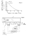
- the invention measures the rate of change of pressure as described in Eq. (2) at several pressures as the pressure in the first chamber 22 decays over a measurement cycle. Referring to Fig. 3, these several pressures include pressures approaching the flowing condition pressure P f and the base condition pressure P b .
- Eq. (2) can be solved at two different pressures P 1 and P 2 .
- P' represents
- Eq. (6) can be further modified to:
- the temperature transfer term can be stated in terms of the virial series as:
- Equation (10) now becomes the basis for measuring the volume correction ratio
- the maximum temperature difference (T b -T f ) should be about ⁇ 10 ° C so the maximum expected variation in the term 1 + [b(T b x) - (T f ,x)] P b is about ⁇ 0.02 to 0.04%.
- Eq. (10) must be determined by either measuring the mass flow rates, ⁇ f for flowing conditions and ⁇ b for base conditions; or holding the rates ⁇ f or ⁇ b constant. If the mass flowrate through the sonic nozzle 28 (i.e., pore 28) is held constant, the ratio of mass flowrates
- the sonic velocity of a fluid v can be accurately represented as:
- Eq. (13) If supercompressibility exists (i.e., the gas is not ideal), the relation in Eq. (13) is not accurate. But Eq. (13) can be modified for non-ideal gases to an equation of the form: where k s is an isentropic exponent. Note that Z is a function of pressure. Gasunie's handbook (cite) uses a formula similar to Eq. (14) , and the Gasunie handbook indicates that it fits data well. In Eq. (14), the isentropic constant k s is a number which forces the P-v relation to accurately approximate the local real gas relation for a small isentropic expansion or compression.
- the mass flowrate WN of sample gas 20 exiting the nozzle 28 (i.e., pore 28), under critical pressure conditions, can be stated as: where the subscript "N" indicates a nozzle mechanical condition, "I” represents a dynamic inlet condition, and AN is the cross-sectional area of the sonic nozzle 28.
- critical flow means a condition where the ratio of pressure upstream from the sonic nozzle 28 compared to the pressure downstream of the sonic nozzle 28 is sufficient so that the relations in Eqs. (14) and (15) for non-ideal gases are substantially accurate.
- the mass flowrate ratio for two states, where pressure in the first chamber 26 is P 1 or P 2 can be represented as:
- the temperature ratio is nearly constant over a single measurement cycle (due to the heat sinking of the assembly) and the ratio can therefore be ignored.
- Equation (18) shows that the low pressure operating conditions at the inlet of the sonic nozzle 28 (i.e., pore 28) are accompanied by supercompressibility effects too small to be of concern when determining the mass flowrate ratio
- Equation (10) can now be rewritten as: where is substituted for and the term ⁇ 1 + [b(T b ,x f )-bT v x f )]P b ⁇ is ignored.
- the pressure decay rate ratio must be determined. The following discussion explains the determination of the pressure decay rate ratio
- Figures 2 and 3 are the results of a computer simulation.
- Figure 2 represents a typical plot of pressure in the first chamber 22 as it decays over a measurement cycle.
- the pressure transducer 30 that senses the pressure in the first chamber 22 should have sufficient bandwidth to accurately measure the pressure in the first chamber 22 throughout the entire measurement cycle.
- the microprocessor 36 records several pressure measurements from transducer 30 as the pressure decays and the time that each pressure measurement occurs.
- the time rate of change of the pressure in the first chamber 22 i.e. P'
- Figure 3 shows the variation in P' versus pressure in the first chamber 22.
- the curvature of P' is due to supercompressibility of the gas.
- P' at flowing conditions P t and at base conditions P b cannot be measured directly without additional apparatus.
- To directly measure P' at P t would require an initial or starting pressure in the first chamber 22 that is higher than the pipeline gas 12 pressure because the P' measurement should be centered about the pipeline gas 12 pressure P f .
- directly measuring P' b would probably require exhausting the first chamber 22 into a partial vacuum. Direct measurement of P' b and P' f does not therefore seem practical.
- Measurement of pressure decay rates P' required to solve Eq. (21) for P' b and P' f can be accomplished in several fashions.
- the preferred method is to divide the time between two pressure measurements At into the difference of the measured pressures AP to obtain values of P' and then use Eq. (21) to interpolate the values of P' b and P' f .
- This method has the advantage of stability and has good resolution because time measurement resolution is very good.
- Another method is to record the absolute pressures in a time series (i.e. record the pressure in the first chamber 22 vs. time as in Fig. 2).
- Numeric differentiation methods can then be applied to transform the pressure time series into normalized P' versus P data as in Fig. 3.
- the numeric differentiation process can be carried out using Newton's formulas for data spaced equally in time, or using LaGrange's formula for data spaced unequally in time. If numeric differentiation is used, it is preferred that a large number of points be employed because numeric differentiation can be a noise amplifying process.
- Analogue differentiation using operational amplifier techniques could also be used to measure P', but the relatively slow nature of the measurement cycle would be a severe complication.
- the value of a single pressure decay rate "n" in a series of pressure decay rate measurements can be described as: where the dependence of Z and c on temperature and composition can be ignored because of the constant composition and relatively constant temperature environment in the first chamber 22.
- the measured value at another point "n + 1 " is:
- the invention can be used to determine a base condition volumetric flowrate Q b of the pipeline gas 12 flowing through the pipeline 14 from a flowing condition volumetric flowrate Q f measured by a volumetric flowmeter (e.g. 38 in Fig. 4 and 40 in Fig. 5):
- FIGs. 4 and 5 flow of sample gas 20 and reference gas is shown by solid lines and electrical connections are shown by dashed lines.
- flow of pipeline gas 12 through an orifice plate 38 produces a pressure drop APt and a DP cell 42 measures the pressure drop ⁇ P f .
- a signal from the DP cell 42 representing APt is sent to the microprocessor 36 to determine the mass flowrate ⁇ f of the pipeline gas 12 through the pipeline 14.
- the mass flowrate ⁇ f through the orifice plate 38 i.e.
- ⁇ f is calculated within the microprocessor 36 from previously gathered data
- Y t is the upstream expansion factor that accounts for changes in pressure as the pipeline gas 12 flows through the orifice 38 (e.g. AGA-3 standard)
- C Df and K are known constants for the orifice plate 38.
- the microprocessor 36 can then determine the flowing condition flowrate Q f for a differential pressure meter by: and the base condition flowrate Q b by:
- Figure 5 shows operation of the invention with a linear volumetric flowmeter, such as a turbine meter, a vortex meter, or any other meter with an output signal linearly proportional to the volumetric flow of the gas 12 through the pipeline.
- a turbine meter 40 is used as shown in Fig. 5
- the flowing condition volumetric flow rate Q f is given by the calibration equation: where f t is the frequency of rotation and K t is a scaling constant.
- the frequency of rotation f t is detected by a frequency detector 41 located on the outer surface of pipeline 14 near impeller 43 of the turbine meter 40.
- the signal from the frequency detector 41 is then relayed to the microprocessor, along with the data used to determine the volume correction ratio
- the microprocessor 36 then calculates the base volumetric flowrate by:
Landscapes
- Physics & Mathematics (AREA)
- General Physics & Mathematics (AREA)
- General Health & Medical Sciences (AREA)
- Chemical & Material Sciences (AREA)
- Analytical Chemistry (AREA)
- Biochemistry (AREA)
- Life Sciences & Earth Sciences (AREA)
- Health & Medical Sciences (AREA)
- Immunology (AREA)
- Pathology (AREA)
- Fluid Mechanics (AREA)
- Measuring Volume Flow (AREA)
- Details Of Flowmeters (AREA)
Applications Claiming Priority (2)
| Application Number | Priority Date | Filing Date | Title |
|---|---|---|---|
| US956143 | 1992-10-05 | ||
| US07/956,143 US5307668A (en) | 1992-10-05 | 1992-10-05 | Gas density meter and method |
Publications (2)
| Publication Number | Publication Date |
|---|---|
| EP0591639A2 true EP0591639A2 (de) | 1994-04-13 |
| EP0591639A3 EP0591639A3 (de) | 1995-03-29 |
Family
ID=25497811
Family Applications (1)
| Application Number | Title | Priority Date | Filing Date |
|---|---|---|---|
| EP93112322A Ceased EP0591639A3 (de) | 1992-10-05 | 1993-07-31 | Gasdichtemesser. |
Country Status (4)
| Country | Link |
|---|---|
| US (1) | US5307668A (de) |
| EP (1) | EP0591639A3 (de) |
| CA (1) | CA2101979A1 (de) |
| MX (1) | MX9305480A (de) |
Cited By (6)
| Publication number | Priority date | Publication date | Assignee | Title |
|---|---|---|---|---|
| WO1996029577A1 (en) * | 1995-03-20 | 1996-09-26 | Badger Meter, Inc. | Method and apparatus for measuring volume correction using molar quantities |
| WO1997022869A1 (en) * | 1995-12-19 | 1997-06-26 | The Dow Chemical Company | Method and apparatus for determining physical properties of a gas by controlled gas injections |
| FR2765966A1 (fr) * | 1997-07-09 | 1999-01-15 | Gaz De France | Procede et dispositif pour determiner la masse volumique d'un gaz |
| EP0861423A4 (de) * | 1995-11-17 | 1999-04-21 | Mks Instr Inc | System zur messung eines gas-massendurchflusses |
| WO1999039181A1 (en) * | 1998-01-30 | 1999-08-05 | Instromet, Inc. | Measurement of relative density of combustible gases |
| EP2806271A1 (de) * | 2013-05-24 | 2014-11-26 | Mems Ag | Verfahren und Messvorrichtung zur Bestimmung von physikalischen Gaseigenschaften |
Families Citing this family (22)
| Publication number | Priority date | Publication date | Assignee | Title |
|---|---|---|---|---|
| US5540077A (en) * | 1994-06-10 | 1996-07-30 | Scott Specialty Gases, Inc. | Method and gas mixture for calibrating an analyzer |
| US6076542A (en) * | 1995-12-01 | 2000-06-20 | Perception Incorporated | Fluid metering method |
| US5902927A (en) | 1995-12-01 | 1999-05-11 | Perception Incorporated | Fluid metering apparatus and method |
| US5656784A (en) * | 1997-01-03 | 1997-08-12 | Eagle Research Corp. | Fluid density variation compensation for fluid flow volume measurement |
| DE59710962D1 (de) * | 1997-08-15 | 2003-12-11 | Alstom Switzerland Ltd | Rohrleitungssystem zur gesteuerten Verteilung eines strömenden Mediums sowie Verfahren zum Betrieb eines solchen Rohrleitungssystems |
| AU739983B2 (en) * | 1998-01-16 | 2001-10-25 | Lattice Intellectual Property Limited | Method and apparatus for measuring the relative density of a gas |
| US6119710A (en) | 1999-05-26 | 2000-09-19 | Cyber Instrument Technologies Llc | Method for wide range gas flow system with real time flow measurement and correction |
| FI107840B (fi) * | 1999-12-09 | 2001-10-15 | Vaisala Oyj | Mittausmenetelmä ja järjestelmä kosteus- tai kaasuanturia varten |
| GB0227109D0 (en) * | 2002-11-20 | 2002-12-24 | Air Prod & Chem | Volume flow controller |
| WO2009134755A2 (en) * | 2008-04-28 | 2009-11-05 | Alexandria Investment Research And Technology, Llc | Adaptive knowledge platform |
| PL2458357T5 (pl) * | 2010-11-29 | 2018-03-30 | Air Products And Chemicals, Inc. | Sposób i urządzenie do mierzenia ciśnienia gazu |
| EP2458348B1 (de) | 2010-11-29 | 2013-08-14 | Air Products And Chemicals, Inc. | Verfahren und Vorrichtung zum Messen der Massendurchflussrate eines Gases |
| ES2749877T3 (es) | 2010-11-29 | 2020-03-24 | Air Prod & Chem | Método y aparato de medición del peso molecular de un gas |
| PL2667159T3 (pl) | 2012-05-24 | 2022-05-02 | Air Products And Chemicals, Inc. | Sposób oraz urządzenie dla mierzenia masowego natężenia przepływu gazu |
| PL2667162T3 (pl) | 2012-05-24 | 2016-03-31 | Air Prod & Chem | Sposób oraz urządzenie do mierzenia właściwości fizycznych płynów dwufazowych |
| EP2667277B1 (de) | 2012-05-24 | 2017-12-27 | Air Products And Chemicals, Inc. | Verfahren und Vorrichtung zur Bereitstellung einer Gasmischung |
| PL2667176T3 (pl) | 2012-05-24 | 2015-07-31 | Air Prod & Chem | Urządzenie do mierzenia rzeczywistej zawartości butli z gazem pod ciśnieniem |
| EP2667276B1 (de) | 2012-05-24 | 2017-11-08 | Air Products And Chemicals, Inc. | Verfahren und Vorrichtung zur Bereitstellung einer Gasmischung |
| PL2667160T3 (pl) | 2012-05-24 | 2021-05-04 | Air Products And Chemicals, Inc. | Sposób i urządzenie do regulowania masowego natężenia przepływu gazu |
| WO2014151475A1 (en) | 2013-03-15 | 2014-09-25 | Watkins Bobby G Ii | Flow control and gas metering process |
| CN105717159A (zh) * | 2016-04-18 | 2016-06-29 | 广东海洋大学 | 用于测定气体比热容比的方法及装置 |
| CN108572014B (zh) * | 2017-12-31 | 2023-03-17 | 深圳市前海海洋仪表科技有限公司 | 超声波水表以及借助超声波水表获取水流温度的方法 |
Family Cites Families (9)
| Publication number | Priority date | Publication date | Assignee | Title |
|---|---|---|---|---|
| US3701280A (en) * | 1970-03-18 | 1972-10-31 | Daniel Ind Inc | Method and apparatus for determining the supercompressibility factor of natural gas |
| US4285245A (en) * | 1979-12-06 | 1981-08-25 | Precision Machine Products, Inc. | Method and apparatus for measuring and controlling volumetric flow rate of gases in a line |
| US4379402A (en) * | 1981-01-22 | 1983-04-12 | Beckman Instruments, Inc. | Gas analysis instrument having flow rate compensation |
| US4527418A (en) * | 1984-02-09 | 1985-07-09 | Honeywell Inc. | Method of measuring specific gravity and apparatus utilizing the same |
| US4677841A (en) * | 1984-04-05 | 1987-07-07 | Precision Measurement, Inc. | Method and apparatus for measuring the relative density of gases |
| GB8719105D0 (en) * | 1987-08-12 | 1987-09-16 | Schlumberger Electronics Uk | Fluid metering |
| US5092159A (en) * | 1990-10-15 | 1992-03-03 | Texaco Inc. | Method and apparatus utilizing a single nozzle for effecting measurment of steam characteristics |
| US5226728A (en) * | 1991-11-04 | 1993-07-13 | Badger Meter, Inc. | Method and apparatus for measuring mass flow and energy content using a differential pressure meter |
| US5201581A (en) * | 1991-11-18 | 1993-04-13 | Badger Meter, Inc. | Method and apparatus for measuring mass flow and energy content using a linear flow meter |
-
1992
- 1992-10-05 US US07/956,143 patent/US5307668A/en not_active Expired - Fee Related
-
1993
- 1993-07-31 EP EP93112322A patent/EP0591639A3/de not_active Ceased
- 1993-08-05 CA CA002101979A patent/CA2101979A1/en not_active Abandoned
- 1993-09-07 MX MX9305480A patent/MX9305480A/es not_active IP Right Cessation
Cited By (12)
| Publication number | Priority date | Publication date | Assignee | Title |
|---|---|---|---|---|
| WO1996029577A1 (en) * | 1995-03-20 | 1996-09-26 | Badger Meter, Inc. | Method and apparatus for measuring volume correction using molar quantities |
| EP0861423A4 (de) * | 1995-11-17 | 1999-04-21 | Mks Instr Inc | System zur messung eines gas-massendurchflusses |
| WO1997022869A1 (en) * | 1995-12-19 | 1997-06-26 | The Dow Chemical Company | Method and apparatus for determining physical properties of a gas by controlled gas injections |
| US5734093A (en) * | 1995-12-19 | 1998-03-31 | The Dow Chemical Company | Method and apparatus for determining physical properties of a gas for use in rheometry |
| FR2765966A1 (fr) * | 1997-07-09 | 1999-01-15 | Gaz De France | Procede et dispositif pour determiner la masse volumique d'un gaz |
| WO1999002964A1 (fr) * | 1997-07-09 | 1999-01-21 | Gaz De France | Procede pour determiner la masse volumique d'un gaz |
| WO1999039181A1 (en) * | 1998-01-30 | 1999-08-05 | Instromet, Inc. | Measurement of relative density of combustible gases |
| US6058761A (en) * | 1998-01-30 | 2000-05-09 | Badger Meter, Inc. | Measurement of relative density of combustible gases |
| EP2806271A1 (de) * | 2013-05-24 | 2014-11-26 | Mems Ag | Verfahren und Messvorrichtung zur Bestimmung von physikalischen Gaseigenschaften |
| US9612229B2 (en) | 2013-05-24 | 2017-04-04 | Mems Ag | Method and measuring apparatus for determining physical properties of gas |
| EP3273237A1 (de) * | 2013-05-24 | 2018-01-24 | Mems Ag | Verfahren und messvorrichtung zur bestimmung von physikalischen gaseigenschaften |
| US10816525B2 (en) | 2013-05-24 | 2020-10-27 | Mems Ag | Method and measuring apparatus for determining physical properties of gas |
Also Published As
| Publication number | Publication date |
|---|---|
| EP0591639A3 (de) | 1995-03-29 |
| CA2101979A1 (en) | 1994-04-06 |
| MX9305480A (es) | 1994-04-29 |
| US5307668A (en) | 1994-05-03 |
Similar Documents
| Publication | Publication Date | Title |
|---|---|---|
| EP0591639A2 (de) | Gasdichtemesser | |
| US5201581A (en) | Method and apparatus for measuring mass flow and energy content using a linear flow meter | |
| US4285245A (en) | Method and apparatus for measuring and controlling volumetric flow rate of gases in a line | |
| US5323657A (en) | Volumetric flow corrector and method | |
| US4096746A (en) | Flow controller-flow sensor assembly for gas chromatographs and the like | |
| JP3577379B2 (ja) | 流量及び圧力の測定及び制御のための方法及び装置 | |
| US5226728A (en) | Method and apparatus for measuring mass flow and energy content using a differential pressure meter | |
| JP3312346B2 (ja) | ボイルの法則を利用した気体流量を決定する方法及び装置 | |
| KR20120049892A (ko) | 상류의 질량 유량 검증 시스템 및 질량 유량 측정 장치의 성능 검증 방법 | |
| US4396299A (en) | Method and apparatus for determining total energy flow in a gas line | |
| US5115687A (en) | Method and apparatus for taking a proportional sample of flowing gas in a line | |
| US4941345A (en) | Method and apparatus for the measurement of gas properties | |
| US5016482A (en) | Method of taking a proportional sample of flowing gas in a line | |
| US4934178A (en) | Method and apparatus for determining the density of a gas | |
| US5551282A (en) | Method and apparatus for measuring volume correction using molar quantities | |
| US5357809A (en) | Volumetric flow corrector having a densitometer | |
| Loianno et al. | A novel dynamic method for the storage of calibration gas mixtures based on thermal mass flow controllers | |
| US3653399A (en) | Gas flow controlling system | |
| JP2000039347A (ja) | 流量検査装置 | |
| Calcatelli et al. | The IMGC-CNR flowmeter for automatic measurements of low-range gas flows | |
| KR20240161159A (ko) | 질량 유량 검증을 위한 방법 및 장치 | |
| WO1996000883A1 (en) | Gas pressure regulator with integrated flow rate measurement | |
| EP0608736B1 (de) | Volumendurchflusskorrektor mit einem Densitometer | |
| Berg et al. | NIST–IMGC comparison of gas flows below one litre per minute | |
| EP0069173B1 (de) | Verfahren und Gerät zum Messen und Regeln des Volumenflusses von Gasen in einem Rohr |
Legal Events
| Date | Code | Title | Description |
|---|---|---|---|
| PUAI | Public reference made under article 153(3) epc to a published international application that has entered the european phase |
Free format text: ORIGINAL CODE: 0009012 |
|
| AK | Designated contracting states |
Kind code of ref document: A2 Designated state(s): BE DE DK ES FR GB IE IT NL |
|
| PUAL | Search report despatched |
Free format text: ORIGINAL CODE: 0009013 |
|
| AK | Designated contracting states |
Kind code of ref document: A3 Designated state(s): BE DE DK ES FR GB IE IT NL |
|
| 17P | Request for examination filed |
Effective date: 19950831 |
|
| GRAG | Despatch of communication of intention to grant |
Free format text: ORIGINAL CODE: EPIDOS AGRA |
|
| 17Q | First examination report despatched |
Effective date: 19971017 |
|
| 18R | Application refused |
Effective date: 19980406 |