EP0591648B1 - Expandierbare ohrlose Schellenstruktur - Google Patents
Expandierbare ohrlose Schellenstruktur Download PDFInfo
- Publication number
- EP0591648B1 EP0591648B1 EP93112892A EP93112892A EP0591648B1 EP 0591648 B1 EP0591648 B1 EP 0591648B1 EP 93112892 A EP93112892 A EP 93112892A EP 93112892 A EP93112892 A EP 93112892A EP 0591648 B1 EP0591648 B1 EP 0591648B1
- Authority
- EP
- European Patent Office
- Prior art keywords
- clamp structure
- band portion
- tool
- tongue
- embossment
- Prior art date
- Legal status (The legal status is an assumption and is not a legal conclusion. Google has not performed a legal analysis and makes no representation as to the accuracy of the status listed.)
- Expired - Lifetime
Links
Images


Classifications
-
- F—MECHANICAL ENGINEERING; LIGHTING; HEATING; WEAPONS; BLASTING
- F16—ENGINEERING ELEMENTS AND UNITS; GENERAL MEASURES FOR PRODUCING AND MAINTAINING EFFECTIVE FUNCTIONING OF MACHINES OR INSTALLATIONS; THERMAL INSULATION IN GENERAL
- F16L—PIPES; JOINTS OR FITTINGS FOR PIPES; SUPPORTS FOR PIPES, CABLES OR PROTECTIVE TUBING; MEANS FOR THERMAL INSULATION IN GENERAL
- F16L33/00—Arrangements for connecting hoses to rigid members; Rigid hose-connectors, i.e. single members engaging both hoses
- F16L33/02—Hose-clips
-
- F—MECHANICAL ENGINEERING; LIGHTING; HEATING; WEAPONS; BLASTING
- F16—ENGINEERING ELEMENTS AND UNITS; GENERAL MEASURES FOR PRODUCING AND MAINTAINING EFFECTIVE FUNCTIONING OF MACHINES OR INSTALLATIONS; THERMAL INSULATION IN GENERAL
- F16J—PISTONS; CYLINDERS; SEALINGS
- F16J3/00—Diaphragms; Bellows; Bellows pistons
- F16J3/04—Bellows
- F16J3/041—Non-metallic bellows
- F16J3/042—Fastening details
-
- F—MECHANICAL ENGINEERING; LIGHTING; HEATING; WEAPONS; BLASTING
- F16—ENGINEERING ELEMENTS AND UNITS; GENERAL MEASURES FOR PRODUCING AND MAINTAINING EFFECTIVE FUNCTIONING OF MACHINES OR INSTALLATIONS; THERMAL INSULATION IN GENERAL
- F16D—COUPLINGS FOR TRANSMITTING ROTATION; CLUTCHES; BRAKES
- F16D3/00—Yielding couplings, i.e. with means permitting movement between the connected parts during the drive
- F16D3/84—Shrouds, e.g. casings, covers; Sealing means specially adapted therefor
- F16D3/843—Shrouds, e.g. casings, covers; Sealing means specially adapted therefor enclosed covers
- F16D3/845—Shrouds, e.g. casings, covers; Sealing means specially adapted therefor enclosed covers allowing relative movement of joint parts due to the flexing of the cover
-
- F—MECHANICAL ENGINEERING; LIGHTING; HEATING; WEAPONS; BLASTING
- F16—ENGINEERING ELEMENTS AND UNITS; GENERAL MEASURES FOR PRODUCING AND MAINTAINING EFFECTIVE FUNCTIONING OF MACHINES OR INSTALLATIONS; THERMAL INSULATION IN GENERAL
- F16L—PIPES; JOINTS OR FITTINGS FOR PIPES; SUPPORTS FOR PIPES, CABLES OR PROTECTIVE TUBING; MEANS FOR THERMAL INSULATION IN GENERAL
- F16L33/00—Arrangements for connecting hoses to rigid members; Rigid hose-connectors, i.e. single members engaging both hoses
- F16L33/02—Hose-clips
- F16L33/035—Hose-clips fixed by means of teeth or hooks
-
- Y—GENERAL TAGGING OF NEW TECHNOLOGICAL DEVELOPMENTS; GENERAL TAGGING OF CROSS-SECTIONAL TECHNOLOGIES SPANNING OVER SEVERAL SECTIONS OF THE IPC; TECHNICAL SUBJECTS COVERED BY FORMER USPC CROSS-REFERENCE ART COLLECTIONS [XRACs] AND DIGESTS
- Y10—TECHNICAL SUBJECTS COVERED BY FORMER USPC
- Y10T—TECHNICAL SUBJECTS COVERED BY FORMER US CLASSIFICATION
- Y10T24/00—Buckles, buttons, clasps, etc.
- Y10T24/14—Bale and package ties, hose clamps
- Y10T24/1457—Metal bands
Definitions
- the present invention relates to a clamp structure which retains an object to be fastened by expansion of its diametric dimension, and in particular to a so-called earless-type clamp structure which is adapted to secure an object to be fastened by an increase in its diametric dimensions.
- So-called earless clamp structures are disclosed in my prior U.S. Patents 4,492,004 and 4,712,278. These prior art clamp structures operate to secure objects, such as hoses and axle boots by reducing the circumferential length of the clamp structure in its installed condition so as to decrease the diametric dimensions thereof. These prior art earless clamp structures offer the advantage of a low profile and reusability by permitting disassembly of the clamp structure from the object by reopening the mechanical connection. These prior art earless clamp structures were thereby mounted externally over the object to be fastened.
- Diaphragm boot designs are presently used in the automotive industry which are located on and secured to the inner tapered surface of so-called can members attached to the end of the drive shafts and made of spun steel. A carbon steel ring, machined with matching taper is pressed into the can member to secure the boot in order to provide a leak-free grease seal. Problems arise with this type of construction in the replacement of the boot and regreasing of the bearings. In case of a damaged boot, a complete drive shaft renewal was required heretofore.
- Another object of the present invention resides in a clamp structure which is reusable so as to allow servicing of the boot in a manner that reduces repair, maintenance and warranty costs.
- a further object of the present invention resides in a clamp structure which secures the object to be fastened thereby by expansion of the clamp structure and which requires only minor modifications in the design of the spun steel parts used heretofore.
- the problems are solved with the features of claim 1.
- the clamp structure in accordance with the present invention is mounted internally of the object to be fastened and applies the required clamping forces by expansion against the internal surfaces of the boot as contrasted with the prior art externally mounted clamp structures which are reduced in diameter to apply compressive forces on the object to be fastened.
- the clamp structure is so arranged that the hook forming part of the mechanical connection extends from the outer band portion inwardly to engage in an opening provided near the free end of the inner band portion.
- the tool-engaging embossments are so arranged that the inwardly extending tool-engaging embossment in the outer band portion is adapted to engage in a longitudinal slot provided in the inner band portion and is able to slide underneath the inwardly extending tool-engaging embossment provided in the inner band portion.
- the parts are thereby so located that the inwardly extending hook in the outer band portion can engage in the corresponding aperture in the inner band portion when the clamp structure has been expanded to a predetermined increased diametric dimension producing the predetermined externally directed clamping forces.
- a bent-out hook extending inwardly from the outer band portion is adapted to engage in a narrow slot in the inner band portion so as to guide the inner and outer band portions relative to one another during installation of the clamp structure.
- over-torquing during tightening of the clamp can be avoided by abutment of the inwardly bent-out hook at the end of the slot after the clamp has been expanded to the point where the inwardly extending hooks in the outer band portion are able to engage into the corresponding apertures in the inner band portion, a very slight extra length of the slot being helpful when the reusable clamp is to be disassembled.
- this can be done without damaging over-torquing yet permits disassembly of the clamp by being able to apply the necessary force to cause disengagement of the hook from the apertures.
- the clamp according to the present invention is thereby installed by applying a tool to oppositely disposed surfaces of the tool-engaging embossments so that contraction of the tools' jaws will cause the tool-engaging embossments to approach one another and thereby cause the clamp structure to increase its diametric dimension.
- means are provided in the clamping band to facilitate disassembly of the clamp for repair and maintenance purposes which are in the form of inwardly pressed-out embossments that extend in the longitudinal direction of the clamping band in the lateral areas thereof.
- these longitudinally extending disassembly-facilitating embossments intended to accommodate a disassembly tool, such as a small screwdriver are located within an area adjoining the step-like portion in a direction toward the free end of the inner band portion.
- the parts in the clamp structure are so arranged according to this invention that the outer clamping surface is devoid of any step at the overlapping end of the outer band portion.
- the clamp structure may also be provided with separate tool-engaging surfaces in the inner and outer band portions for tightening and disassembling the clamp structure.
- the clamp structure generally designated by reference numeral 10 includes a clamping band 20 made from any suitable material such as stainless steel or galvanized steel which is cut to appropriate length from a roll of band material to provide a flat blank and is stamped out as a flat blank to provide the following features.
- the clamp structure includes a tab-like longitudinally extending guide hook 23 bent out of the band material at approximately right angle whereby its tip can be bent over once more at substantially right angle in the preassembled condition of the clamp structure so as to extend more or less parallel to the inner surface of the inner clamping band portion 20b and thereby lock the clamp in the preassembled condition.
- a cold-deformed tool-engaging embossment 24 pressed inwardly out of the outer band portion 20a follows the hook 23 and is preferably integral with the outer clamping band portion 20a except along a transverse cut 24' so that it forms a more or less semi-circular opening within the area of the transverse cut 24' for engagement by the tip portion 31b of the fastening tool generally designated by reference numeral 30 ( Figure 3).
- an inwardly extending support hook 25 which forms part of the mechanical connection for connecting overlapping outer and inner band portions 20a and 20b, respectively.
- the support hook 25 may be of any known construction such as shown, for example, in my aforementioned U.S. Patents 4,492,004 or 4,712,278.
- a narrow longitudinal slot 26 for engagement by the guide hook 23 which, in turn, is adjoined by a wider longitudinal slot 27.
- a wider longitudinal slot 27 At the end of slot 27 near the free end of the inner band portion 20b is another cold-deformed inwardly extending tool-engaging embossment 28 which is integral with the inner band portion 20b along its longitudinal sides.
- the tool-engaging embossment 28 is thereby pressed out inwardly after transverse cuts 28' and 28'' whereby the thus-formed more or less semi-circular opening provides for the engagement by the tip portion 31a of the fastening tool 30.
- An opening 29 is provided between the tool-engaging embossment 28 and the free end of the inner band portion 20b for engagement by the inwardly extending support hook 25.
- the tool-engaging embossments are of at least approximately complementary shape so that the tool-engaging embossment 24 can slide under the tool-engagement embossment 28 during tightening of the clamp.
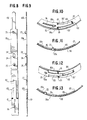
- the clamp structure shown in Figures 1 and 2 is bent in such a manner that the guide hook 23 in the form of an inwardly directly circumferentially extending tab-like member can engage into narrow slot 26 and the support hook 25 as well as the tool-engaging embossment 24 extend inwardly through the slot 27.
- Preassembly of the parts is attained by simply bending over the outer end of guide hook 23 so as to extend substantially parallel to the inner surface.
- the clamp structure By applying pressure by means of the fastening tool 30 onto the tool-engaging embossments 24 and 28 as schematically indicated in Figures 3 and 4, the clamp structure will increase its effective circumferential length and therewith its diametric dimension until the parts reach the position shown in Figures 5, 6 and 7 in which the hook-like support member 25 engages in opening 29.
- the dimensions and locations of the various parts are thereby so chosen that in the position of the clamp structure shown in Figures 5 through 7, the clamp 20 presses the boot generally designated by reference numeral 50 against the internal surface of the can member generally designated by reference numeral 40, the shape of which forms no part of the present invention.
- An annular groove 41 provided near its inwardly extending rim portion 42 may contribute to the secure fastening of the boot 50 to the can member 40.
- the clamp structure in accordance with the present invention is reusable, i.e., can be reopened by simply lifting the opening 29 out of engagement with the hook-like support member 25. A reduction in repair, maintenance and warranty costs is assured thereby.
- the tight seal achieved with the clamp structure in accordance with the present invention provides a readily serviceable product assuring a joint performance which does not deteriorate.
- the clamp can be preassembled into the position shown in Figures 3 and 4 in which it can be supplied to the customer in the thus-reduced dimensions.
- Drawing together the two tool-engaging embossments 24 and 28 causes the outer diameter of the clamp structure to expand until the support hook 25 can engage in opening 29.
- the outer diameter of the clamp structure is expanded as a result of the particular constriction and location of its parts.
- All protruding parts of the clamp structure are located along the internal circumference of the clamp structure so that the smooth external surface of the clamping band is able to compress the boot material against the internal surface of the can member 40 to force the boot material into the annular groove 41 and preclude its movement in the axial direction by the boot rim portion 51 which is clamped fast between the clamp structure 20 and the rim portion 42 of the can member 40.
- the embodiment of the clamp structure illustrated in Figures 8-13 differs from the clamp structure of Figures 1-7 only by an arrangement which effectively provides an external clamping surface devoid of any step. This is achieved by the use of a tongue-like extension 130 at the end of the outer clamping band portion 20a which is adapted to slidingly engage in a central pressed-out torque-receiving channel 120 which is pressed out from the inner band portion 20b in the radially inward direction.
- the tongue-receiving channel 120 is thereby formed between two step-like portions 121 and 122 whereby the channel 120 is pressed out in the radially inward direction after one or several longitudinal cuts leaving lateral band portions 20' and 20" on both sides thereof.
- Step-like portions 121 thereby raise the lateral band portions 20 and 20' to the height of the channel 120 so that the full band width is again available in the inner band portion 20b to the left of step-like portions 121 ( Figures 10 and 12).
- the arrangement is thereby made in a manner somewhat analogous to that disclosed in my prior U.S. Patent 4,299,012.
- the tongue-like extension 130 will slide in a direction in which its immersion in the tongue-receiving channel 120 decreases.
- the outwardly exposed length of the tongue-like extension 130 between the step-like portions 121 and the end of the outer band portion 20a increases.
- the greater length of the exposed tongue-like portion 130 does not impair the holding ability of the clamp structure as the tongue-like extension 130 is positively guided intermediate the step-like portions 121 and the end of the outer band portion 20a by abutment at the outer surface of the inner band portion 20b which has the full band width within this area.
- the length of exposed tongue-like portion 130 can be minimized.
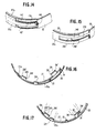
- Figure 14 illustrates a modified embodiment of a clamp structure in accordance with the present invention in which the inner band portion 20b is provided with an arrangement somewhat analogous to my prior U.S. Patent 4,237,584 to achieve an external clamping surface devoid of any steps. More particularly, the inner band portion 20b is provided with pressed-out embossments 142 and 142' forming in effect a U-shaped fork-like tongue-receiving channel generally designated by reference numeral 140 to receive the tongue-like extension 130 at the end of the outer band portion 20a.
- the arrangement is thereby made in such a manner that the ends of pressed-out embossments 142 and 142' which are disposed opposite the free end of the inner band portion 20b, i.e., the right ends as viewed in Figure 14 merge smoothly into the remaining areas of the inner band portion so that the full band width exists again to the right thereof and the outer clamping surface of the clamp structure has a circular configuration defined by outer band portion 20a, tongue-like extension 130 adjoined laterally by embossments 142, 142' and the extension of the inner band portion 20b at the right end of embossments 142 and 142' which is devoid of any step or offset in the continuous effective clamping surface.
- Figure 15 illustrates a still further modified embodiment in accordance with the present invention which is merely a reversal of the parts of the embodiment of Figure 14. More particularly, the end of the outer band portion 20a is provided in this embodiment with a U-shaped fork-like tongue-receiving channel generally designated by reference numeral 240 formed by lateral fork-like portions 242 and 242' and intended to receive the tongue-like extension 230 pressed out of the inner band portion 20b.
- reference numeral 240 formed by lateral fork-like portions 242 and 242' and intended to receive the tongue-like extension 230 pressed out of the inner band portion 20b.
- the embodiment of the clamp structure of Figures 16 and 17 differs from the preceding embodiments by a structural arrangement precluding over-torquing during tightening and facilitating disassembly of the clamp structure.
- the embossment 328 which is again at least approximately semi-circularly shaped and may have a configuration similar to embossment 28 and integral with the inner clamping band portion 20b, includes end surfaces 328' and 328'', of which the end surface 328'' constitutes a tool-engaging surface for the application of disassembly forces.
- a pressed-out tool-engaging clamp releasing embossment 324 for releasing the clamp which may have a configuration similar to that of embossment 24 is provided in the outer band portion 20a.
- the pressed-out tool-engaging embossments 28 and 24 again constitute with their tool-engaging abutment surfaces the means for tightening the clamp structure.
- the tool-engaging pressed-out embossments 324 and 328 constitute with their tool-engaging surfaces the release means to reopen the clamp.
- any of the arrangements of Figures 8-15 may also be used.
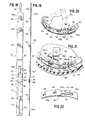
- FIGS 18 through 24 illustrate a preferred modified embodiment of a clamp structure in accordance with the present invention in which reference numerals of the 400 series are used to designate parts corresponding to the previous embodiments.
- the clamp structure of Figures 18 through 23 generally designated by reference numeral 410 includes again a clamping band 420 whose inner and outer clamping band portions 420b and 420a respectively overlap in the closed condition of the clamp structure. Proceeding from the inner clamping band end 420b toward the outer clamping band end 420a, a narrow longitudinal slot 426 is adjoined by the inwardly extending first tool-engaging embossment 428 which is followed by the wider longitudinal opening 427.
- a tongue-receiving means generally designated by reference numeral 440 commences in the area of the step-like portions 421 which raise the lateral band portions 420' and 420" remaining on both sides of the tongue-receiving means 440 to the height of the inner band portion 420b.
- the tongue-receiving means 440 may be in the form of a central tongue-receiving channel as disclosed in connection with Figures 12 and 13 or may be in the form of an opening beginning within the area of the step-like portions 421 as disclosed in my prior U.S. Patent 4,315,348.
- the tongue-receiving means 440 is formed in part of a centrally disposed opening 440' which commences within the area of the step-like portion 420 and is adjoined by a centrally-disposed tongue-receiving channel 440'' for reasons to be explained hereinafter. Proceeding toward the outer band end portion 420a, a tab-like longitudinally extending guide hook 423 is followed by a second pressed-out inwardly extending tool-engaging embossment 424 that is followed by the inwardly extending support hook 425. The outer band portion 420a terminates in a tongue-like extension 430.
- tongue-receiving means formed in part by opening 440' and in part by tongue-receiving channel 440'' is based on the recognition that it is preferable for the support hook 425 to be able to extend through an opening such as opening 440' when the clamp structure is in its closed preassembled, but not yet tightened position.
- a tool-engaging disassembly means generally designated by reference numeral 460 is provided in the embodiment of Figures 18 through 23 which is constituted by lateral pressed-out inwardly extending embossments 460' and 460'' disposed on both sides of the clamping band and located within the area between the step-like portions 421 and the end of the longitudinal opening 427 opposite the end of the inner band portion 420b.
- the disassembly tool-engaging embossments 460' and 460'' are formed by longitudinal cuts leaving a central web portion 461 in the clamping band whereby the embossments 460' and 460'' are pressed-out inwardly in a more or less semi-circular shape for insertion of a disassembly tool, such as a small screwdriver 480 to facilitate disassembly of the installed clamp ( Figure 23).
- a disassembly embossments 460' and 460'' are provided on both sides of the clamping band so that the screwdriver can be inserted from either side in such a manner that it can also extend over the web portion 461.
- Figure 20 illustrates the clamp structure in its closed condition before it is tightened while Figure 21 illustrates how the clamp is tightened by the use of a special tool generally designated by reference numeral 530 ( Figure 24).
- Figure 22 illustrates a modified arrangement for avoiding steps at the end of the outer band end portion 420a.
- the clamp structures in accordance with the present invention are designed for specific predetermined hose sizes, the required diametric dimension as also the necessary location of the various parts in the longitudinal direction of the clamp are known beforehand.
- the clamp structure may be so designed that during tightening, i.e., expanding of the clamp structure the outer band end portion 420a has just moved beyond the step-like portions 421.
- the fact that during installation the outer band end portion 420a and its tongue-like extension 430 may form steps is of no consequence as such steps then disappear in the fully engaged position.
- Figure 24 illustrates the special tool 530 for use with a clamp structure in accordance with the present invention which is installed by radial expansion thereof.
- the tool includes two handle portions 531a and 531b which are pivotally connected with one another at 532.
- the corresponding parts 531a' and 531b' on the other side of the pivotal connection 532 are provided with oppositely directed step-like portions so that the jaw-like parts 533a and 533b are in the same plane.
- the jaw-like end portions 533a' and 533b' are bent off at right angle with respect to the parts 533a and 533b and are formed with nose-like pointed end portions 534a and 534b for engagement in the tool-engaging embossments 424 and 428.
- These nose-like portions end 534a and 534b are formed in effect by the ground side surfaces 536a and 536b and the part-circularly shaped inner surfaces 535a and 535b forming a nearly circular opening therebetween.
- disassembly tool-engaging embossments 460' and 460'' of the embodiment of Figures 18 through 23 may also be incorporated in an analogous manner in the preceding embodiments to facilitate disassembly.
- the clamping band of the various embodiments may also be provided with one or more sections adapted to impart elastic stretchability in the longitudinal direction of the clamping band, as disclosed in my prior U.S. Patent 4,987,651, the subject matter of which is incorporated herein by reference.
- the use of such section(s) will permit the clamp structure, otherwise substantially devoid of elastic stretchability, to permit breathing of the hose in the presence of temperature and/or pressure fluctuations without affecting the holding ability of the clamp structure.
Landscapes
- Engineering & Computer Science (AREA)
- General Engineering & Computer Science (AREA)
- Mechanical Engineering (AREA)
- Clamps And Clips (AREA)
- Joints That Cut Off Fluids, And Hose Joints (AREA)
- Transition And Organic Metals Composition Catalysts For Addition Polymerization (AREA)
- Adhesives Or Adhesive Processes (AREA)
Claims (17)
- Klemmenstruktur zum Aufbringen von Haltekräften durch Aufweiten ihres Durchmessermaßes, umfassend eine Klemmbandeinrichtung (20) mit inneren und äußeren, einander überlappenden Bandteilen (20a, 20b; 420a, 420b), eine mechanische Verbindungseinrichtung zum Verbinden der einander überlappenden Bandteile mit einer Öffnungsanordnung (27, 29; 427) im inneren Bandteil und einer vom äußeren Bandteil nach innen verlaufenden hakenartigen Einrichtung (25; 425) zum Eingriff mit der Öffnungsanordnung im inneren Bandteil, wobei die Öffnungsanordnung eine längliche Öffnung (27; 427) im inneren Bandteil aufweist, eine im inneren Bandteil nahe der länglichen Öffnung angeordnete erste, nach innen ragende Werkzeug-Eingriffseinrichtung (28; 428), und eine im äußeren Bandteil vorgesehene zweite nach innen ragende Werkzeug-Eingriffseinrichtung (24; 424), die nahe der hakenartigen Einrichtung derart angeordnet ist, daß eine an der ersten und der zweiten Werkzeug-Eingriffseinrichtung angreifende Kraft, die diese gegeneinander zu ziehen sucht, bewirkt, daß sich die Klemmenstruktur in ihrem Durchmessermaß aufweitet und dabei die Haltekräfte erzeugt.
- Klemmenstruktur nach Anspruch 1, wobei die erste Werkzeug-Eingriffseinrichtung (428) zwischen der länglichen Öffnung (427) und dem freien Ende des inneren Bandteils (420b) und die hakenartige Einrichtung (425) zwischen der zweiten Werkzeug-Eingriffseinrichtung (424) und dem freien Ende des äußeren Bandteils (420a) angeordnet ist.
- Klemmenstruktur nach Anspruch 1 oder 2 mit einer Führungseinrichtung, die ein im äußeren Bandteil (20a; 420a) angeordnetes, nach innen ragendes und in Längsrichtung verlaufendes laschenartiges Element (23; 423) aufweist, das so betätigbar ist, daß es in einen schmalen Schlitz (26; 426) im inneren Bandteil (20b; 420b) eingreift.
- Klemmenstruktur nach Anspruch 3 mit einer Vormontageeinrichtung zum Vormontieren der Klemmenstruktur in einer Stellung, in der sich ihre Teile in einem Durchmessermaß befinden, das gegenüber dem im eingebauten Zustand gewünschten aufgeweiteten Durchmessermaß verringert ist, wobei die Vormontageeinrichtung von einem umgebogenen äußeren Teil des laschenartigen Elements (23; 423) gebildet ist, um die Klemmenstruktur im vormontierten Zustand zu halten.
- Klemmenstruktur nach einem der Ansprüche 1 bis 4, wobei die erste Werkzeug-Eingriffseinrichtung (28; 428) eine nach innen herausgedrückte, kalt verformte Prägung ist, deren Länge von dem dem freien Ende des inneren Bandteils (20b; 420b) zugewandten Ende der länglichen Öffnung (27; 427) und einem nahe dem Ende der länglichen Öffnung (27; 427) und dem freien Ende des inneren Bandteils (20b; 420b) gelegenen quer verlaufenden Schnitt in der Klemmbandeinrichtung bestimmt ist, wobei die Seiten der ersten Werkzeug-Eingriffsprägung mit der übrigen Klemmbandeinrichtung im wesentlichen einstückig zusammenhängen, wobei die erste Werkzeug-Eingriffseinrichtung (28; 428) einen mindestens näherungsweise halbkreisförmigen Querschnitt aufweist, wobei die zweite Werkzeug-Eingriffseinrichtung (24; 424) eine mit dem äußeren Bandteil mit Ausnahme eines im wesentlichen quer verlaufenden Schnittes einstückige, nach innen herausgedrückte, kaltverformte Prägung ist, und wobei die zweite Werkzeug-Eingriffseinrichtung (24; 424) eine Querschnittsform aufweist, die zu der der ersten Werkzeug-Eingriffseinrichtung (28; 428) im wesentlichen komplementär ist und um ein solches Stück nach innen ragt, daß sie unter die erste Werkzeug-Eingriffseinrichtung gleiten kann.
- Klemmenstruktur nach einem der Ansprüche 1 bis 5, wobei die Öffnungsanordnung eine Aussparung (29) zum Eingriff mit der hakenartigen Anordnung (25) im aufgeweiteten Zustand der Klemmenstruktur umfaßt, wobei die erste Werkzeug-Eingriffseinrichtung (28) innerhalb des Bereichs zwischen der länglichen Öffnung (27) und der Aussparung (29) angeordnet ist, und wobei, ausgehend vom freien Ende des inneren Bandteils (20b) in Richtung des freien Endes des äußeren Bandteils (20a), auf die im Endbereich des inneren Bandteils (20b) angeordnete Aussparung (29) die erste Werkzeug-Eingriffseinrichtung (28) folgt, an die sich die längliche Öffnung (27) anschließt, auf die ihrerseits der schmale Schlitz (26) folgt, an den sich weiter in Richtung des freien Endes des äußeren Bandteils (20a) die hakenartige Einrichtung (25), die zweite Werkzeug-Eingriffseinrichtung (24) und das laschenartige Teil (23) der Führungseinrichtung anschließen.
- Klemmenstruktur nach einem der Ansprüche 1 bis 5, wobei die Öffnungsanordnung ferner eine Aussparung (440) innerhalb desjenigen Bereichs der Klemmbandeinrichtung umfaßt, die der länglichen Öffnung (427) auf der vom freien Ende des inneren Bandteils (420b) abgewandten Seite benachbart ist, und wobei die hakenartige Einrichtung (425) in der Klemmbandeinrichtung derartig angeordnet ist, daß sie im Vormontagezustand, in dem die zweite Werkzeug-Eingriffseinrichtung (424) durch die längliche Öffnung (427) ragt, die Aussparung (440) durchsetzt.
- Klemmenstruktur nach einem der Ansprüche 1 bis 7 mit ferner einer in der Klemmbandeinrichtung vorhandenen, die Demontage erleichternden Einrichtung (328, 324; 460, 460') zur Aufnahme eines Demontagewerkzeugs zum Lösen der hakenartigen Einrichtung aus der Öffnungsanordnung.
- Klemmenstruktur nach Anspruch 8, wobei die die Demontage erleichternde Einrichtung eine nach innen herausgedrückte Demontagewerkzeug-Eingriffseinrichtung (460', 460") aufweist, die effektiv eine von seitlichen Prägungen gebildete, in Längsrichtung der Klemmbandeinrichtung verlaufende seitlich zugängliche Öffnung bildet.
- Klemmenstruktur nach Anspruch 9, wobei die seitliche Prägungen (460, 460") auf beiden Seiten von in der Klemmbandeinrichtung vorhandenen Längsschnitten angeordnet sind, die einen dazwischen verbleibenden mittleren Stegabschnitt (461) definieren, und wobei die seitlichen Prägungen in Seitenansicht mindestens näherungsweise teilkreisförmige Gestalt haben.
- Klemmenstruktur nach einem der Ansprüche 1 bis 10 mit einer zusätzlichen Einrichtung, die am Ende des äußeren Klemmbandteils eine von jeglicher Stufe freie äußere Klemmfläche gewährleistet und in den überlappenden Bandteilen eine zungenartige Einrichtung (130; 230; 430) und eine Zungen-Aufnahmeeinrichtung (120; 140; 240; 440) umfaßt.
- Klemmenstruktur nach Anspruch 11, wobei die zungenartige Einrichtung am äußeren Bandteil (20a; 420a) eine zungenartige Verlängerung (130; 430) zum Eingriff in eine Zungen-Aufnahmeeinrichtung (120; 140; 440) im inneren Bandteil (20b; 420b) aufweist, wobei die Zungen-Aufnahmeeinrichtung an einem stufenartigen Abschnitt (121; 421) beginnt, wobei neben der mittig angeordneten Zungen-Aufnahmeeinrichtung seitliche Bandabschnitte (20', 20"; 142, 142; 420', 420") verbleiben, wobei der stufenartige Abschnitt die auf beiden Seiten der mittig angeordneten Zungen-Aufnahmeeinrichtung verbleibenden seitlichen Bandteile radial nach innen um ein Maß versetzt, das im wesentlichen der Dicke der Klemmbandeinrichtung entspricht, und wobei die Zungen-Aufnahmeeinrichtung mindestens teilweise von einem mittig angeordneten Kanal gebildet ist, der in einem zweiten stufenartigen Abschnitt (122) endet.
- Klemmenstruktur nach Anspruch 11 oder 12, wobei die zungenartige Einrichtung (130) am Ende des äußeren Bandteils (20a) und die Zungen-Aufnahmeeinrichtung von einen näherungsweise U-förmigen Zungen-Aufnahmekanal bildenden Prägungen (142, 142') gebildet ist, die aus dem inneren Bandteil um ein Maß herausgedrückt sind, das näherungsweise der Dicke der Klemmbandeinrichtung entspricht, und wobei die verbleibenden seitlichen Bandteile auf beiden Außenseiten der Prägungen sowie der zwischen ihnen liegende Bandteil an den vom freien Ende des inneren Bandteils abgewandten Enden der Prägungen allmählich in diese übergehen.
- Klemmenstruktur nach Anspruch 11 oder 12, wobei die Zungen-Aufnahmeeinrichtung (140) von einem einen Zungen-Aufnahmekanal am Ende des äußeren Bandteils bildenden, im wesentlichen U-förmigen gabelartigen Teil (242, 242') und die zungenartige Anordnung von einer herausgedrückten Prägung (230) gebildet ist, die so angeordnet und gestaltet ist, daß sie in den von dem U-förmigen Teil (240) gebildeten Kanal hinein und aus diesem herausgleiten kann, und wobei die seitlichen Bandteile auf beiden Seiten der Prägung (230) an dem vom freien Ende des inneren Bandteils abgewandten Ende der Prägung allmählich in deren Außenfläche übergehen.
- Klemmenstruktur nach einem der Ansprüche 1 bis 14 mit ferner einer Einrichtung, die beim Spannen der Klemmenstruktur ein Überdehnen verhindert.
- Klemmenstruktur nach einem der Ansprüche 1 bis 14 mit ferner einer Einrichtung, die bei der Demontage der Klemmenstruktur ein Überdehnen verhindert.
- Klemmenstruktur nach einem der Ansprüche 1 bis 16 zum Befestigen eines ersten Bauteils (50) aus weicherem Material an einem zweiten Bauteil (40) aus härterem Material, wobei das zweite Bauteil (40) eine zur Außenfläche der Klemmenstruktur im wesentlichen parallele Innenfläche aufweist, das erste Bauteil (50) längs der Innenfläche des zweiten Bauteils (40) angeordnet und die Klemmenstruktur an der Innenfläche des ersten Bauteils (50) derart angelegt wird, daß sie unter Aufweitung der Klemmenstruktur das erste Bauteil an dem zweiten Bauteil hält, und wobei das zweite Bauteil (40) eine Ringnut (41) aufweist, in die das erste Bauteil (50) beim Einbau der Klemmenstruktur unter Aufweitung hineingedrückt wird.
Applications Claiming Priority (2)
| Application Number | Priority Date | Filing Date | Title |
|---|---|---|---|
| US958765 | 1992-10-09 | ||
| US07/958,765 US5333360A (en) | 1992-10-09 | 1992-10-09 | Expandable clamp structure of the earless type |
Publications (2)
| Publication Number | Publication Date |
|---|---|
| EP0591648A1 EP0591648A1 (de) | 1994-04-13 |
| EP0591648B1 true EP0591648B1 (de) | 1996-11-13 |
Family
ID=25501272
Family Applications (1)
| Application Number | Title | Priority Date | Filing Date |
|---|---|---|---|
| EP93112892A Expired - Lifetime EP0591648B1 (de) | 1992-10-09 | 1993-08-11 | Expandierbare ohrlose Schellenstruktur |
Country Status (9)
| Country | Link |
|---|---|
| US (1) | US5333360A (de) |
| EP (1) | EP0591648B1 (de) |
| JP (1) | JP3462540B2 (de) |
| KR (1) | KR100245055B1 (de) |
| AT (1) | ATE145270T1 (de) |
| CA (1) | CA2104275C (de) |
| DE (1) | DE69305957T2 (de) |
| ES (1) | ES2093894T3 (de) |
| MX (1) | MX9306270A (de) |
Cited By (1)
| Publication number | Priority date | Publication date | Assignee | Title |
|---|---|---|---|---|
| KR100893467B1 (ko) | 2001-03-26 | 2009-04-17 | 한스 외티커 아게 마쉬넨-운트 아파라테파브리크 | 튜브 클램프 |
Families Citing this family (16)
| Publication number | Priority date | Publication date | Assignee | Title |
|---|---|---|---|---|
| US5333100A (en) * | 1992-06-29 | 1994-07-26 | Itt Corporation | Data card perimeter shield |
| US6010324A (en) * | 1996-01-30 | 2000-01-04 | Toshiba Kikai Kabushiki Kaisha | Mold clamping unit and method of positioning mold in mold clamping unit |
| EP0918185A3 (de) * | 1997-11-20 | 2001-03-07 | Hans Oetiker AG Maschinen- und Apparatefabrik | Expandierbare Klemmbandvorrichtung |
| US6457212B1 (en) * | 2001-02-07 | 2002-10-01 | Hans Oetiker Ag Maschinen- Und Apparatefabrik | Method of making hose clamps with internal clamping surfaces devoid of steps or gaps and products made by such method |
| US6866301B2 (en) * | 2002-07-31 | 2005-03-15 | Npc, Inc. | Expandable band and locking mechanism |
| US7243956B2 (en) * | 2002-07-31 | 2007-07-17 | Npc, Inc. | Expandable band and locking mechanism |
| JP3783018B2 (ja) * | 2004-01-15 | 2006-06-07 | 株式会社三木製作所 | 可撓継手の固定リング |
| KR100732156B1 (ko) | 2005-12-22 | 2007-06-25 | 주식회사 한강개발 | 관로 보수부재의 연속설치공법 |
| DE112006000575T5 (de) * | 2005-03-16 | 2008-01-24 | Hangangcc Co. Ltd., Namyangju | Material zur aushubfreien Reparatur eines Rohrs und Reparaturverfahren |
| US9890879B2 (en) * | 2008-02-26 | 2018-02-13 | Gates Corporation | Hose anti-collapse ribs, systems and methods |
| US9038671B2 (en) * | 2008-02-26 | 2015-05-26 | Gates Corporation | Hose anti-collapse ribs, systems and methods |
| CA2716219A1 (en) * | 2009-09-29 | 2011-03-29 | Press-Seal Gasket Corporation | Collapsible expansion mechanism for effecting a seal |
| CA2734855C (en) | 2010-03-23 | 2014-07-15 | Press-Seal Gasket Corporation | Expansion ring assembly |
| JP4744640B1 (ja) | 2010-10-15 | 2011-08-10 | 株式会社ミハマ | 締付けバンド |
| US12339029B2 (en) | 2022-07-29 | 2025-06-24 | Christopher Henry Benoit | Expandable plenum flange and method of use |
| GB2637000B (en) * | 2024-01-02 | 2026-04-29 | Cross Mfg Company 1938 Limited | Ring fastener with locking feature |
Family Cites Families (8)
| Publication number | Priority date | Publication date | Assignee | Title |
|---|---|---|---|---|
| US3160425A (en) * | 1960-12-22 | 1964-12-08 | Victor B Sinnott | Anti-root sewer pipe liner |
| FR1347808A (fr) * | 1962-11-20 | 1964-01-04 | Glaenzer Spicer Sa | Dispositif pour la fixation des soufflets d'étanchéité utilisés notamment pour les joints universels |
| GB1416877A (en) * | 1972-11-28 | 1975-12-10 | Carr Fastener Co Ltd | Clip for securing compliant tubular members |
| US4478437A (en) * | 1981-07-27 | 1984-10-23 | Press/Seal Gasket Corp. | Radially expandable locking sleeve device |
| US4987651A (en) * | 1989-09-20 | 1991-01-29 | Hans Oetiker Ag Maschinen- Und Apparatefabrik | Earless clamp |
| US5029907A (en) * | 1989-04-14 | 1991-07-09 | Npc, Inc. | Band for effecting a seal |
| US5033167A (en) * | 1990-07-12 | 1991-07-23 | Gkn Automotive Inc. | Low profile clamp |
| US5150927A (en) * | 1991-01-22 | 1992-09-29 | Press Seal Gasket Corporation | Expandable seal arrangement |
-
1992
- 1992-10-09 US US07/958,765 patent/US5333360A/en not_active Expired - Lifetime
-
1993
- 1993-08-11 AT AT93112892T patent/ATE145270T1/de active
- 1993-08-11 ES ES93112892T patent/ES2093894T3/es not_active Expired - Lifetime
- 1993-08-11 EP EP93112892A patent/EP0591648B1/de not_active Expired - Lifetime
- 1993-08-11 DE DE69305957T patent/DE69305957T2/de not_active Expired - Lifetime
- 1993-08-17 CA CA002104275A patent/CA2104275C/en not_active Expired - Fee Related
- 1993-10-08 KR KR1019930020777A patent/KR100245055B1/ko not_active Expired - Fee Related
- 1993-10-08 JP JP25304993A patent/JP3462540B2/ja not_active Expired - Fee Related
- 1993-10-08 MX MX9306270A patent/MX9306270A/es not_active IP Right Cessation
Cited By (2)
| Publication number | Priority date | Publication date | Assignee | Title |
|---|---|---|---|---|
| KR100893467B1 (ko) | 2001-03-26 | 2009-04-17 | 한스 외티커 아게 마쉬넨-운트 아파라테파브리크 | 튜브 클램프 |
| KR100943102B1 (ko) * | 2001-03-26 | 2010-02-18 | 한스 외티커 아게 마쉬넨-운트 아파라테파브리크 | 튜브 클램프 |
Also Published As
| Publication number | Publication date |
|---|---|
| JPH06193785A (ja) | 1994-07-15 |
| US5333360A (en) | 1994-08-02 |
| DE69305957T2 (de) | 1997-05-22 |
| KR940009540A (ko) | 1994-05-20 |
| ATE145270T1 (de) | 1996-11-15 |
| CA2104275C (en) | 2005-02-08 |
| DE69305957D1 (de) | 1996-12-19 |
| KR100245055B1 (ko) | 2000-03-02 |
| CA2104275A1 (en) | 1994-04-10 |
| MX9306270A (es) | 1994-06-30 |
| JP3462540B2 (ja) | 2003-11-05 |
| ES2093894T3 (es) | 1997-01-01 |
| EP0591648A1 (de) | 1994-04-13 |
Similar Documents
| Publication | Publication Date | Title |
|---|---|---|
| EP0591648B1 (de) | Expandierbare ohrlose Schellenstruktur | |
| EP2118551B1 (de) | Gestufte kugelgelenk-rohrklemme und voranbringungskomponenten dafür | |
| US6088886A (en) | Hose clamp having a spring ring disposed within the clamp | |
| US4299012A (en) | Hose clamp | |
| EP0499819B1 (de) | Einsatzkörper für Anwendung in Schlauchklemmen | |
| US5299344A (en) | Reinforcing arrangement for open hose clamps, especially screw-type hose clamps | |
| US4165109A (en) | Wide-band compression coupling | |
| EP0763688B1 (de) | Rohrverbindung | |
| JP3513238B2 (ja) | 耳無しおよび段無しクランプ構造体 | |
| EP0570742B1 (de) | Wiederverwendbare ohrlose Rohrschelle | |
| KR20160072111A (ko) | 파이프 결합구 | |
| CA1291862C (en) | Earless clamp structure | |
| US5581851A (en) | Draw operating type clamping device | |
| US6240603B1 (en) | Hose clamp with stepless internal clamping surface and method of making the same | |
| KR100625140B1 (ko) | 호스 클램프용 조임 수단 | |
| MXPA04011157A (es) | Abrazadera abierta de manguera con oreja plasticamente deformable y metodo para elaborar la misma. | |
| US12442472B2 (en) | Pipe joint, gland, and method for joining pipes | |
| US20060117534A1 (en) | Open hose clamp with plastically deformable ear | |
| CA2086468C (en) | Self-aligning clamp structure | |
| HK1050925B (en) | Hose clamp with stepless internal clamping surface and method of making the same |
Legal Events
| Date | Code | Title | Description |
|---|---|---|---|
| PUAI | Public reference made under article 153(3) epc to a published international application that has entered the european phase |
Free format text: ORIGINAL CODE: 0009012 |
|
| AK | Designated contracting states |
Kind code of ref document: A1 Designated state(s): AT BE CH DE ES FR GB GR IT LI LU NL PT SE |
|
| 17P | Request for examination filed |
Effective date: 19940321 |
|
| 17Q | First examination report despatched |
Effective date: 19950927 |
|
| GRAH | Despatch of communication of intention to grant a patent |
Free format text: ORIGINAL CODE: EPIDOS IGRA |
|
| GRAH | Despatch of communication of intention to grant a patent |
Free format text: ORIGINAL CODE: EPIDOS IGRA |
|
| GRAA | (expected) grant |
Free format text: ORIGINAL CODE: 0009210 |
|
| ITF | It: translation for a ep patent filed | ||
| AK | Designated contracting states |
Kind code of ref document: B1 Designated state(s): AT BE CH DE ES FR GB GR IT LI LU NL PT SE |
|
| PG25 | Lapsed in a contracting state [announced via postgrant information from national office to epo] |
Ref country code: GR Free format text: LAPSE BECAUSE OF FAILURE TO SUBMIT A TRANSLATION OF THE DESCRIPTION OR TO PAY THE FEE WITHIN THE PRESCRIBED TIME-LIMIT Effective date: 19961113 |
|
| REF | Corresponds to: |
Ref document number: 145270 Country of ref document: AT Date of ref document: 19961115 Kind code of ref document: T |
|
| REG | Reference to a national code |
Ref country code: CH Ref legal event code: NV Representative=s name: TROESCH SCHEIDEGGER WERNER AG |
|
| REF | Corresponds to: |
Ref document number: 69305957 Country of ref document: DE Date of ref document: 19961219 |
|
| REG | Reference to a national code |
Ref country code: ES Ref legal event code: FG2A Ref document number: 2093894 Country of ref document: ES Kind code of ref document: T3 |
|
| REG | Reference to a national code |
Ref country code: PT Ref legal event code: SC4A Free format text: AVAILABILITY OF NATIONAL TRANSLATION Effective date: 19961113 |
|
| ET | Fr: translation filed | ||
| PLBE | No opposition filed within time limit |
Free format text: ORIGINAL CODE: 0009261 |
|
| 26N | No opposition filed | ||
| REG | Reference to a national code |
Ref country code: GB Ref legal event code: IF02 |
|
| PGFP | Annual fee paid to national office [announced via postgrant information from national office to epo] |
Ref country code: NL Payment date: 20100810 Year of fee payment: 18 Ref country code: ES Payment date: 20100915 Year of fee payment: 18 Ref country code: CH Payment date: 20100817 Year of fee payment: 18 |
|
| PGFP | Annual fee paid to national office [announced via postgrant information from national office to epo] |
Ref country code: SE Payment date: 20100817 Year of fee payment: 18 Ref country code: LU Payment date: 20100915 Year of fee payment: 18 Ref country code: IT Payment date: 20100814 Year of fee payment: 18 Ref country code: FR Payment date: 20100824 Year of fee payment: 18 Ref country code: AT Payment date: 20100818 Year of fee payment: 18 |
|
| PGFP | Annual fee paid to national office [announced via postgrant information from national office to epo] |
Ref country code: GB Payment date: 20100817 Year of fee payment: 18 |
|
| PGFP | Annual fee paid to national office [announced via postgrant information from national office to epo] |
Ref country code: PT Payment date: 20100727 Year of fee payment: 18 |
|
| PGFP | Annual fee paid to national office [announced via postgrant information from national office to epo] |
Ref country code: DE Payment date: 20101021 Year of fee payment: 18 Ref country code: BE Payment date: 20100818 Year of fee payment: 18 |
|
| REG | Reference to a national code |
Ref country code: PT Ref legal event code: MM4A Free format text: LAPSE DUE TO NON-PAYMENT OF FEES Effective date: 20120213 |
|
| BERE | Be: lapsed |
Owner name: HANS *OETIKER A.G. MASCHINEN- UND APPARATEFABRIK Effective date: 20110831 |
|
| REG | Reference to a national code |
Ref country code: NL Ref legal event code: V1 Effective date: 20120301 |
|
| REG | Reference to a national code |
Ref country code: CH Ref legal event code: PL |
|
| REG | Reference to a national code |
Ref country code: SE Ref legal event code: EUG |
|
| GBPC | Gb: european patent ceased through non-payment of renewal fee |
Effective date: 20110811 |
|
| PG25 | Lapsed in a contracting state [announced via postgrant information from national office to epo] |
Ref country code: LI Free format text: LAPSE BECAUSE OF NON-PAYMENT OF DUE FEES Effective date: 20110831 Ref country code: CH Free format text: LAPSE BECAUSE OF NON-PAYMENT OF DUE FEES Effective date: 20110831 |
|
| REG | Reference to a national code |
Ref country code: FR Ref legal event code: ST Effective date: 20120430 |
|
| PG25 | Lapsed in a contracting state [announced via postgrant information from national office to epo] |
Ref country code: PT Free format text: LAPSE BECAUSE OF NON-PAYMENT OF DUE FEES Effective date: 20120213 Ref country code: IT Free format text: LAPSE BECAUSE OF NON-PAYMENT OF DUE FEES Effective date: 20110811 Ref country code: BE Free format text: LAPSE BECAUSE OF NON-PAYMENT OF DUE FEES Effective date: 20110831 Ref country code: NL Free format text: LAPSE BECAUSE OF NON-PAYMENT OF DUE FEES Effective date: 20120301 |
|
| REG | Reference to a national code |
Ref country code: DE Ref legal event code: R119 Ref document number: 69305957 Country of ref document: DE Effective date: 20120301 |
|
| PG25 | Lapsed in a contracting state [announced via postgrant information from national office to epo] |
Ref country code: GB Free format text: LAPSE BECAUSE OF NON-PAYMENT OF DUE FEES Effective date: 20110811 Ref country code: FR Free format text: LAPSE BECAUSE OF NON-PAYMENT OF DUE FEES Effective date: 20110831 |
|
| REG | Reference to a national code |
Ref country code: AT Ref legal event code: MM01 Ref document number: 145270 Country of ref document: AT Kind code of ref document: T Effective date: 20110811 |
|
| PG25 | Lapsed in a contracting state [announced via postgrant information from national office to epo] |
Ref country code: AT Free format text: LAPSE BECAUSE OF NON-PAYMENT OF DUE FEES Effective date: 20110811 |
|
| PG25 | Lapsed in a contracting state [announced via postgrant information from national office to epo] |
Ref country code: SE Free format text: LAPSE BECAUSE OF NON-PAYMENT OF DUE FEES Effective date: 20110812 |
|
| PG25 | Lapsed in a contracting state [announced via postgrant information from national office to epo] |
Ref country code: LU Free format text: LAPSE BECAUSE OF NON-PAYMENT OF DUE FEES Effective date: 20110811 |
|
| REG | Reference to a national code |
Ref country code: ES Ref legal event code: FD2A Effective date: 20130531 |
|
| PG25 | Lapsed in a contracting state [announced via postgrant information from national office to epo] |
Ref country code: DE Free format text: LAPSE BECAUSE OF NON-PAYMENT OF DUE FEES Effective date: 20120301 |
|
| PG25 | Lapsed in a contracting state [announced via postgrant information from national office to epo] |
Ref country code: ES Free format text: LAPSE BECAUSE OF NON-PAYMENT OF DUE FEES Effective date: 20110812 |