EP0591659A1 - Système de commande pour un dispositif d'alimentation de produits imprimés vers une station de traitement ultérieur - Google Patents
Système de commande pour un dispositif d'alimentation de produits imprimés vers une station de traitement ultérieur Download PDFInfo
- Publication number
- EP0591659A1 EP0591659A1 EP93113254A EP93113254A EP0591659A1 EP 0591659 A1 EP0591659 A1 EP 0591659A1 EP 93113254 A EP93113254 A EP 93113254A EP 93113254 A EP93113254 A EP 93113254A EP 0591659 A1 EP0591659 A1 EP 0591659A1
- Authority
- EP
- European Patent Office
- Prior art keywords
- rocker
- drive
- controller
- control arrangement
- intermediate stack
- Prior art date
- Legal status (The legal status is an assumption and is not a legal conclusion. Google has not performed a legal analysis and makes no representation as to the accuracy of the status listed.)
- Granted
Links
Images


Classifications
-
- B—PERFORMING OPERATIONS; TRANSPORTING
- B65—CONVEYING; PACKING; STORING; HANDLING THIN OR FILAMENTARY MATERIAL
- B65H—HANDLING THIN OR FILAMENTARY MATERIAL, e.g. SHEETS, WEBS, CABLES
- B65H43/00—Use of control, checking, or safety devices, e.g. automatic devices comprising an element for sensing a variable
- B65H43/06—Use of control, checking, or safety devices, e.g. automatic devices comprising an element for sensing a variable detecting, or responding to, completion of pile
-
- B—PERFORMING OPERATIONS; TRANSPORTING
- B65—CONVEYING; PACKING; STORING; HANDLING THIN OR FILAMENTARY MATERIAL
- B65H—HANDLING THIN OR FILAMENTARY MATERIAL, e.g. SHEETS, WEBS, CABLES
- B65H29/00—Delivering or advancing articles from machines; Advancing articles to or into piles
- B65H29/003—Delivering or advancing articles from machines; Advancing articles to or into piles by grippers
-
- B—PERFORMING OPERATIONS; TRANSPORTING
- B65—CONVEYING; PACKING; STORING; HANDLING THIN OR FILAMENTARY MATERIAL
- B65H—HANDLING THIN OR FILAMENTARY MATERIAL, e.g. SHEETS, WEBS, CABLES
- B65H29/00—Delivering or advancing articles from machines; Advancing articles to or into piles
- B65H29/66—Advancing articles in overlapping streams
- B65H29/669—Advancing articles in overlapping streams ending an overlapping stream
-
- B—PERFORMING OPERATIONS; TRANSPORTING
- B65—CONVEYING; PACKING; STORING; HANDLING THIN OR FILAMENTARY MATERIAL
- B65H—HANDLING THIN OR FILAMENTARY MATERIAL, e.g. SHEETS, WEBS, CABLES
- B65H83/00—Combinations of piling and depiling operations, e.g. performed simultaneously, of interest apart from the single operation of piling or depiling as such
- B65H83/02—Combinations of piling and depiling operations, e.g. performed simultaneously, of interest apart from the single operation of piling or depiling as such performed on the same pile or stack
-
- B—PERFORMING OPERATIONS; TRANSPORTING
- B65—CONVEYING; PACKING; STORING; HANDLING THIN OR FILAMENTARY MATERIAL
- B65H—HANDLING THIN OR FILAMENTARY MATERIAL, e.g. SHEETS, WEBS, CABLES
- B65H2301/00—Handling processes for sheets or webs
- B65H2301/40—Type of handling process
- B65H2301/44—Moving, forwarding, guiding material
- B65H2301/447—Moving, forwarding, guiding material transferring material between transport devices
- B65H2301/4471—Grippers, e.g. moved in paths enclosing an area
- B65H2301/44712—Grippers, e.g. moved in paths enclosing an area carried by chains or bands
-
- B—PERFORMING OPERATIONS; TRANSPORTING
- B65—CONVEYING; PACKING; STORING; HANDLING THIN OR FILAMENTARY MATERIAL
- B65H—HANDLING THIN OR FILAMENTARY MATERIAL, e.g. SHEETS, WEBS, CABLES
- B65H2301/00—Handling processes for sheets or webs
- B65H2301/40—Type of handling process
- B65H2301/44—Moving, forwarding, guiding material
- B65H2301/447—Moving, forwarding, guiding material transferring material between transport devices
- B65H2301/4472—Suction grippers, e.g. moved in paths enclosing an area
Definitions
- the invention relates to a control arrangement for a device for feeding printed products to a further processing point, with a first conveyor device for feeding the printed products in a row formation, with a second conveyor device for taking over and further transporting the supplied printed products and with a rocker arranged in the conveyor area of the first conveyor device, wherein on the rocker from the supplied printed products at a stop an intermediate stack fed from below is formed, from which the uppermost printed product is transferred to the second conveyor by a lifting device, and wherein the control arrangement detects a predetermined height of the top of the intermediate stack with a sensor and by acting on a drive of the rocker lowers and raises it and thus keeps the top of the intermediate stack essentially at the predetermined height.
- Such a control arrangement is part of a device of the aforementioned type, which is the subject of the unpublished GB-A-2260 123 or the corresponding EP-A-0 551 601.
- the supply of the printed products to the second conveyor is decoupled to a certain extent from the supply of the printed products by the first conveyor, so that the gaps are too large or too small successive printed products or densification of a shingled stream (if, as in the older proposal, the series formation is a shingled formation in which each printed product rests on the next one) and also missing printed products in the series formation no longer influence the correct feeding of printed products to the second conveyor , Irregularities in the supplied row formation are thus compensated for by the intermediate stack.
- the control arrangement according to the older proposal which detects a predetermined height of the top of the intermediate stack and lowers and raises it by acting on a drive of the rocker and thus keeps the top of the intermediate stack essentially at the predetermined height, has a height monitoring control with which Help in the manner of a two-point control the top of the intermediate stack is essentially maintained at the predetermined level.
- the change in the height of the upper side of the intermediate stack which is caused by irregularities in the given row formation, can be taken into account, but not the speed of change in the height, which is dependent on the volume of printed matter supplied by the first conveyor per unit of time.
- an intermediate stack is also used, the height of which is to be regulated to a level that is as constant as possible.
- the intermediate stack is loaded from above, and the bottom printed product is removed from the intermediate stack.
- This intermediate stacking principle is very simple, but its application possibilities are limited.
- An intermediate stack principle as in the applicant's older proposal, in which the intermediate stack is fed from below, is more versatile, but also more difficult to regulate.
- a series of twenty-four sensors arranged one above the other measures the level height in the print-roll machine, from whose derivation the speed of change in the level height is additionally determined becomes.
- This known system therefore necessarily requires a considerable height of the intermediate stack, so that its height and the change in height can be determined by the sensors. This in turn has the consequence that the intermediate stack has a considerable weight and can make it difficult to remove the bottom printed product.
- the control arrangement is complex in this system, despite the simple intermediate stacking principle, because it is not a pure fuzzy controller that is intrinsically complex, but a hybrid solution in which a conventional digital PI controller is superimposed on a fuzzy control.
- the object of the invention is to provide a control arrangement of the type mentioned at the outset such that changes in the volume of printed products which are fed to the intermediate stack by the first conveyor per unit of time occur in the control process in a simple manner and while maintaining a low height of the intermediate stack and thus one allow for the light weight of the same and a small stroke range of the rocker.
- a control arrangement of the type mentioned at the outset is characterized by a first controller which operates the rocker drive at an adjustable speed in a range between two stroke limits of the rocker, by an actual value transmitter for detecting the lifting movement of the rocker, and by a second controller, which forms a control value for the speed of the drive of the first conveyor with a setpoint dependent on the detected stroke movement and thus the volume of printed matter per unit of time that the intermediate stack through the first conveyor is supplied, depending on the stroke movement of the rocker controls.
- the rocker which is driven at an adjustable speed, is moved in a partial region between its two stroke limits, that is to say in a region which usually does not reach up to the two stroke limits, and a desired value for the second controller is formed with the stroke movement detected in the process that controls the speed of the drive of the first conveyor.
- the stroke control of the rocker is used according to the invention to regulate the feed speed. This means that, for example, when thick printed products are fed, there is a greater stroke movement for the partial area within the two stroke limits of the rocker and thus a larger setpoint value and thus, in turn, a higher speed of the first conveyor than in the case in which thin printed products are processed .
- the height of the top of the intermediate stack is therefore regulated quickly or slowly, i.e. thicker printed products are supplied later by the first conveyor than thinner printed products, for example to make gaps in the row or scale formation faster or slower close.
- the invention thus creates an adaptive control arrangement that automatically takes changes in the volume of printed products into account in a simple manner.
- the stack height can still be small, as in the applicant's older proposal, which means that the intermediate stack is light in weight and thus facilitates loading of the intermediate stack from below.
- the control arrangement according to the invention is characterized by two limit switches which define the maximum upper or maximum lower stroke limit of the rocker for safety and initialization purposes and switch off or reverse the drive of the rocker when actuated.
- the rocker is constantly moved back and forth between the two maximum stroke limits, but usually not up to the maximum stroke limits, but only to the extent or only up to the point in time at which the predetermined height of the top of the intermediate stack again is reached.
- the limit switches are therefore not involved in the control process, apart from the initialization phase. They are mainly used for security.
- the sensor sets the zero point for the specified sub-range.
- control arrangement is characterized in that the first controller has a first input for entering a setpoint for the adjustable speed of the drive of the rocker. Via this input, the speed of the rocker drive can be specified in accordance with the operating requirements in the rest of the system.
- control arrangement according to the invention is characterized in that the first input of the controller is connected to a speed signal output of a drive of the second conveyor.
- the stroke movement speed of the rocker to be detected for the control process can be easily synchronized with the drive of the second conveyor device, which feeds the printed matter to the finishing station.
- control arrangement according to the invention is characterized in that the first input of the first controller is connected to a potentiometer serving as a setpoint generator.
- a potentiometer serving as a setpoint generator.
- control arrangement is characterized in that the sensor is designed as a light barrier and acts on the drive of the rocker via the first controller, such that the rocker moves downwards when the light beam is interrupted and upwards when the light beam is not interrupted or vice versa. If the light beam is interrupted (or released) by the intermediate stack, the direction of movement of the rocker reverses and the rocker is moved down until the light barrier is free (or interrupted again), whereupon the rocker is raised again is moved until the light beam is interrupted (or released again), etc. It is therefore possible, while maintaining the light barrier, as is provided according to the older proposal of the applicant, to increase the speed of the drive of the first conveyor in a simple manner influence in order to quickly eliminate the cause of the change in the intermediate stack height.
- control arrangement according to the invention is characterized in that the actual value transmitter is a pulse generator which is one of the pulse sequence dependent on the size and direction of the lifting movement of the rocker. This enables a particularly simple and practical evaluation of the stroke movement speed of the rocker.
- control arrangement according to the invention is characterized in that the output of the actual value transmitter is connected to at least one second input of the first controller.
- the stroke movement of the rocker detected as a pulse sequence can serve to determine the actual value of this speed for the process of regulating the speed of the drive of the rocker. If a motor with an adjustable constant speed were used as a drive for the rocker, the aforementioned detection of the actual value of the speed could be omitted, so that a simple speed control device could be used instead of the first controller.
- control arrangement is characterized in that the output of the actual value transmitter is connected to a detector circuit which has a decoder for detecting the direction of stroke movement and a counter for counting the pulses from the first actual value transmitter, and that the detector circuit is connected via a D / A converter is connected to a setpoint input of the second controller and supplies it with the setpoint from which the second controller forms the manipulated value for the speed of the drive of the first conveyor by comparison with its actual speed value.
- This is an expedient embodiment of the invention for evaluating the pulse sequence corresponding to the stroke movement of the rocker according to size and direction. Depending on the direction of rotation, the pulse sequence controls the counter so that it counts up or down, so that the setpoint that is fed to the second controller varies accordingly, for example as voltage or as frequency at the output of the D / A converter.
- control arrangement according to the invention is characterized by a setpoint adjustment device which is connected between the D / A converter and the setpoint input of the second controller and, in a further embodiment of the control arrangement according to the invention, can be a potentiometer.
- the setpoint can also be changed proportionally, depending on the incoming scale flow.
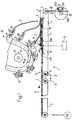
- a device for feeding printed products to a further processing point has a first conveying device 1, which feeds printed products 2 in a scale formation S.
- S is in this scale formation each printed product 2 on the subsequent printed product 2.
- the printed products could be fed by the first conveyor generally in any other row formation, for example in a row in which there are gaps between adjacent printed products.
- the scale formation itself could also have gaps, intentionally or unintentionally.
- the conveyor device 1 has a belt conveyor 3 and an apron conveyor 4 connected downstream of this.
- the apron conveyor 4 is formed by a number of round aprons running parallel to one another and at a distance from one another, which are guided over deflecting rollers 6 and 7, of which one deflecting roller is driven, preferably by one and the same drive M3 as the belt conveyor 3 via a dashed line Drive connection 8.
- the belt conveyor 3 and the apron conveyor 4 can have the same conveying speed.
- the apron conveyor 4 is part of a rocker designated 5 in its entirety.
- the rocker 5 can be pivoted on the one hand about an axis 6 'of the deflection roller 6 and, on the other hand, is supported on a rack 10 which is only shown schematically in FIG. 1.
- a rack 10 which meshes with a pinion 50, the pivot position of the rocker 5 is set in a manner to be described.
- a stop 11 which has a number of stop fingers (only the front one of which is visible in FIGS. 1 and 2), which are arranged at a distance from one another and each between two round straps extend.
- a conveyor roller 13 is provided in front of the stop 11, which extends transversely to the conveying direction A and rests on the scale formation S.
- the conveyor roller 13, which can be driven by the drive M3 via a drive connection, also not shown, exerts a conveying effect on the printed products 2. Thanks to its oscillating mounting, it can adapt to a changing height of the scale formation S.
- the printed products 2 are stacked to form an intermediate stack 29 between the conveyor roller 13 and the stop 11.
- a support plate (not shown) is arranged below the round apron, which prevents the round aprons from bending under the weight of the intermediate stack 29.
- the printed products 2 are inserted into the intermediate stack 29 from below by the apron conveyor 4.
- the driven conveyor roller 13 supports the insertion of the printed products 2 into the intermediate stack 29.
- the feed movement of the printed products 2 is braked by the stop 11.
- the printed products 2 are fed to the intermediate stack 29 as a continuous stream of shingles, as in the exemplary embodiment shown here, it is not difficult to insert the printed products into the intermediate stack at the bottom.
- the underside of the intermediate stack 29 always has such a height above the apron conveyor 4 and the support plate, not shown, at least on the left side of the intermediate stack in Fig. 1 that each subsequent printed product can be pushed under the intermediate stack 29.
- a lifting device 51 is indicated which can work in cycles, for example in cycles by the printed products arriving at the intermediate stack.
- a similar device (not shown) can be used as that which is the subject of a further older proposal by the applicant (European patent application No. 93 105 576.8 of April 3, 1993 and corresponding US patent application No. 08/053 918 of 04/27/1993).
- an auxiliary belt equipped with an adhesive surface which together with the first conveyor device would form a conveyor gap narrowing towards the intermediate stack, would in each case the rear edge of a printed product pending at the stop 11 up to a further stop lift, which in the present case would be on the left side of the intermediate stack in FIG. 1. At this further stop, the trailing edges of printed products already in the intermediate stack would be lifted up.
- a sensor in the form of a light barrier LS1 is part of a control arrangement described in more detail below with additional reference to FIG. 3, which essentially maintains a predetermined height H of the upper side 29a of the intermediate stack 29 by lowering and raising the rocker by means of a drive M2 detected.
- a second conveyor 32 is arranged above the rocker 5, which has individually controllable grippers 33 which are attached at regular intervals to an endless chain, not shown, which runs in the direction of an arrow B.
- a lifting device is provided in the form of a suction device arrangement, generally designated 44, which can be moved up and down.
- the uppermost printed product 2 in the intermediate stack 29 is gripped by the suction arrangement 44 and taken upwards into the conveying area F of the conveying device 32.
- the edges of the printed products 2 are thus brought into the path of movement of an open gripper 33, which is then closed in a manner not of interest here.
- the printed products 2 gripped by the grippers 33 are then completely lifted off the intermediate stack 29 and guided upwards to a further processing point, not shown. Because the printed products 2 fed by the belt conveyor 3 are not fed directly to the grippers 33 which follow one another at fixed intervals, but rather to the intermediate stack 29, there are any irregularities in the scale spacing, ie in the distance between successive ones Printed products 2 in the scale formation S, as well as missing printed products 2 in the scale formation S, have no influence on a perfect takeover by the grippers 33, provided, however, that the predetermined height H of the upper side 29a of the intermediate stack 29 by the control arrangement now described in the following is essentially maintained.
- the removal of the printed products from the intermediate stack 29 by means of the conveying device 32 can also be controlled, and this control process can be taken into account when supplying printed products to the intermediate stack 29. If, for example, no printed product is removed from the intermediate stack for a certain time interval or only a certain number per unit of time, then the drive of the first conveyor can be acted upon accordingly, in order to take this into account, so that the first conveyor supplies nothing or less than for this time interval otherwise. Since the upper side 29a of the intermediate stack 29 remains at a height H for the specified time interval, the effect on the drive of the first conveying device also readily results for the controlled removal from the following description of the mode of operation of the control arrangement.
- the control arrangement has a first controller R1, in whose control loop the drive M2 for lifting the rocker 5 is located, and a second controller R2, in whose control loop the drive M3 of the first conveying device 1 is located.
- the drives M2 and M3 are electric motors.
- the pinion 50 which meshes with the rack 10, is seated on the output shaft of the drive M2, as is shown schematically in FIG. 1.
- the limit switches serve as safety shutdown switches.
- mechanical stops can be provided for this (not shown).
- the first controller R1 causes the drive M2 to be driven at a selectable speed.
- a first input 54a of the first controller R1 is connected to a potentiometer 55 which serves as a setpoint generator and which supplies a setpoint n2 s .
- the first input 54a of the first controller R1 could be connected to a speed signal output 53 (cf. FIG. 1) of the drive M1 of the second conveyor device 32 (FIG. 1).
- a simple control device i.e. without feedback
- the first controller R1 receives on a second in the manner described in more detail below Input 54b is an actual value n2 i of the speed of drive M2 and forms a manipulated value n2 f for drive M2 by comparison with setpoint n2 s .
- a third input 57 of the first controller R1 is connected to an output of the light barrier LS1. This connection serves to control the reversal of the direction of rotation of the drive M2 as soon as the light beam from the light barrier is interrupted or is no longer interrupted (or vice versa), as described in more detail below in connection with the mode of operation of the control arrangement.
- the drive M2 which could also be an electrohydraulic actuator, is here a brushless, electronically commutated DC motor with an integrated rotor position sensor, which also supplies a tacho signal used by the first controller R1 as a tacho signal, i.e. as the actual value n2 i .
- the controllers R1 and R2 used here are pulse duration modulated controllers, the controls being designed for both directions of rotation.
- Hall generators built into the drives M2 and M3 serve as rotor position sensors.
- the rotor position sensor is shown schematically in FIG. 2 as a separate actual value sensor 56.
- the actual value transmitter 56 or rotor position transmitter viewed in its overall function, is a pulse transmitter which outputs an impulse sequence which is dependent on the size and direction of the lifting movement of the rocker 5 at an output 56a.
- the output 56a of the actual value transmitter 56 is, as explained, connected to the second input 54b of the first controller R1.
- the output 56a of the actual value transmitter 56 is connected to a detector circuit, designated overall by 58, which has a decoder 58a for detecting the direction of stroke movement of the rocker 5 and a counter 58b for counting the pulses from the actual value transmitter 56.
- the detector circuit 58 is via a digital / analog (D / A) converter 59 with a setpoint input 60a of the second controller R2 and supplies it with a setpoint n3 s , from which the second controller R2 forms a manipulated value n3 f for the speed n3 of the drive M3 of the first conveyor 1 by comparison with its actual speed value n3 i , as shown in FIG. 2 is shown schematically and is easily understandable.
- the decoder 58a is an integrated circuit which recognizes the direction of rotation of the drive M2 on the basis of the pulse sequence and has the counter count up or down in such a way that the setpoint n3 s according to the characteristic curve in FIG. 3 with an assumed stroke of 50 mm between 0- 10 volts varies.
- a setpoint value setting device 62 in the form of a potentiometer or the like connected between the D / A converter 59 and the setpoint input 60a of the second controller R2. the setpoint can be changed proportionally if necessary, depending on the incoming scale flow.
- the control arrangement works as follows: In an initialization phase, the first controller R1 switches on the drive M2, which drives the rack 10 down until the limit switch ES1 is actuated, whereupon the direction of rotation of the drive M2 changes and the latter now moves the rack 10 upward. Now the height control phase begins, in which the height H of the upper side 29a of the intermediate stack 29 is to be detected and essentially maintained.
- the detector circuit 58 and the D / A converter 59 begin with the detection of the pulses from the actual value transmitter 56 and the formation of the target value for the drive M3.
- the counter 58b starts counting the pulses from the actual value transmitter 56. It is assumed that an intermediate stack 29 has already been formed on the stop 11.
- the The direction of rotation of the drive M2 is reversed again (as mentioned usually before actuation of the upper limit switch ES2), so that it moves the rack 10 downwards until the light barrier LS1 is free again, whereupon the direction of rotation of the drive M2 is reversed again (this time via the Controller R1, i.e. without the aid of the limit switch ES1), and the drive M2 moves the rack 10 up again until the light beam from the light barrier LS1 is interrupted again, etc.
- the decoder 58a recognizes the direction of rotation on the basis of the pulse sequence and controls the counter in this way forwards / backwards, that the setpoint n3 s varies in a sub-range between 0-10 volts, e.g. between 0 and 8 volts, the size of this sub-range depending on how large the stroke movement between each two reversal of the drive M2 has been .
- the greater this stroke movement the greater the target value n3 s , and the more the speed n3 of the drive M3 of the first conveyor device 1 is increased in order to fill up the intermediate stack 29 again the faster.
- the control arrangement thus regulates the feed speed of the first conveyor 1 by regulating the height of the rocker 5. When the control arrangement is switched off, the drive M2 moves the rack 10 down until the counter reading is zero.
- the shingled stream consists of single sheets, for example, a small stroke movement is carried out between two reversal of the direction of rotation of the drive M2, which results in a small setpoint n3 s for the drive M3, so that the speed n3 requires only a slight correction, that is to say the first conveying device 1 can be slow to run.
- the shingled stream consists of thicker printed products, larger and faster lifting movements are required, which give larger values of the setpoint n3 s and thus to accelerate the first conveying device 1 lead. This is important so that the first conveyor device 1 supplies thicker printed products faster in order to be able to fill the intermediate stack correspondingly faster.
- the belt conveyor 3 is usually supplied with printed products 2 by means of a so-called DISC system or by some other storage unit or by feeding bars.
- DISC system or by some other storage unit or by feeding bars.
- manual loading by means of a manual system is also possible.
- the drive M4 is indicated by dashed lines in Fig. 2, the manual system itself is not shown. It could consist of a belt conveyor similar to the belt conveyor 3, which is provided instead of the latter or in addition to the latter. In the former case, the drive M4 would replace the drive M3, in the latter case the drives M3 and M4 would both be provided and would be used alternatively if required.
Landscapes
- Engineering & Computer Science (AREA)
- Mechanical Engineering (AREA)
- Sheets, Magazines, And Separation Thereof (AREA)
- Control Of Conveyors (AREA)
- Separation, Sorting, Adjustment, Or Bending Of Sheets To Be Conveyed (AREA)
- Conveyance By Endless Belt Conveyors (AREA)
- Feeding Of Articles By Means Other Than Belts Or Rollers (AREA)
- Discharge By Other Means (AREA)
- Handling Of Cut Paper (AREA)
- Delivering By Means Of Belts And Rollers (AREA)
Applications Claiming Priority (2)
| Application Number | Priority Date | Filing Date | Title |
|---|---|---|---|
| CH3098/92 | 1992-10-05 | ||
| CH309892 | 1992-10-05 |
Publications (2)
| Publication Number | Publication Date |
|---|---|
| EP0591659A1 true EP0591659A1 (fr) | 1994-04-13 |
| EP0591659B1 EP0591659B1 (fr) | 1996-07-17 |
Family
ID=4248579
Family Applications (1)
| Application Number | Title | Priority Date | Filing Date |
|---|---|---|---|
| EP93113254A Expired - Lifetime EP0591659B1 (fr) | 1992-10-05 | 1993-08-19 | Système de commande pour un dispositif d'alimentation de produits imprimés vers une station de traitement ultérieur |
Country Status (4)
| Country | Link |
|---|---|
| US (1) | US5419678A (fr) |
| EP (1) | EP0591659B1 (fr) |
| JP (1) | JP3385433B2 (fr) |
| DE (2) | DE4241885C1 (fr) |
Cited By (1)
| Publication number | Priority date | Publication date | Assignee | Title |
|---|---|---|---|---|
| EP2380835A3 (fr) * | 2010-04-20 | 2013-07-03 | Heidelberger Druckmaschinen AG | Dispositif d'application de couverture |
Families Citing this family (3)
| Publication number | Priority date | Publication date | Assignee | Title |
|---|---|---|---|---|
| JPH0924605A (ja) * | 1995-06-22 | 1997-01-28 | Grapha Holding Ag | 紙葉もしくは印刷全紙および入紙を結束された製品に処理するための装置の処理効率を最適化するための方法およびこの方法を実施するための装置 |
| DK1364900T3 (da) * | 2002-05-22 | 2006-11-27 | Ferag Ag | Fremgangsmåde til transport af flade, fleksible produkter og indretning til udövelse af fremgangsmåden |
| DE102008029496A1 (de) * | 2008-06-20 | 2009-12-24 | Krones Ag | Bereitstellung von Zuschnitten bei der Herstellung von Gebinden |
Citations (1)
| Publication number | Priority date | Publication date | Assignee | Title |
|---|---|---|---|---|
| CH630583A5 (de) * | 1978-06-30 | 1982-06-30 | Ferag Ag | Vorrichtung zum wegfoerdern von in einem schuppenstrom anfallenden flaechigen erzeugnissen, insbesondere druckprodukten. |
Family Cites Families (5)
| Publication number | Priority date | Publication date | Assignee | Title |
|---|---|---|---|---|
| FR2357456A1 (fr) * | 1976-07-09 | 1978-02-03 | Martin Sa | Dispositif d'empilage de plaques |
| US4667953A (en) * | 1985-08-28 | 1987-05-26 | Mitsubishi Jukogyo Kabushiki Kaisha | Sheet stacker |
| DE3614884A1 (de) * | 1986-05-02 | 1987-11-05 | Will E C H Gmbh & Co | Stapelvorrichtung |
| AU645716B2 (en) * | 1992-01-09 | 1994-01-20 | Ferag Ag | Process and apparatus for delivering preferably folded printing products to a further processing point |
| EP0567807B1 (fr) * | 1992-04-27 | 1997-06-18 | Ferag AG | Poste de traitement actif pour un courant de produits imprimés en formation imbriquée |
-
1992
- 1992-12-11 DE DE4241885A patent/DE4241885C1/de not_active Expired - Fee Related
-
1993
- 1993-08-19 EP EP93113254A patent/EP0591659B1/fr not_active Expired - Lifetime
- 1993-08-19 DE DE59303247T patent/DE59303247D1/de not_active Expired - Lifetime
- 1993-10-04 US US08/131,138 patent/US5419678A/en not_active Expired - Lifetime
- 1993-10-05 JP JP27495793A patent/JP3385433B2/ja not_active Expired - Fee Related
Patent Citations (1)
| Publication number | Priority date | Publication date | Assignee | Title |
|---|---|---|---|---|
| CH630583A5 (de) * | 1978-06-30 | 1982-06-30 | Ferag Ag | Vorrichtung zum wegfoerdern von in einem schuppenstrom anfallenden flaechigen erzeugnissen, insbesondere druckprodukten. |
Cited By (1)
| Publication number | Priority date | Publication date | Assignee | Title |
|---|---|---|---|---|
| EP2380835A3 (fr) * | 2010-04-20 | 2013-07-03 | Heidelberger Druckmaschinen AG | Dispositif d'application de couverture |
Also Published As
| Publication number | Publication date |
|---|---|
| US5419678A (en) | 1995-05-30 |
| JP3385433B2 (ja) | 2003-03-10 |
| DE4241885C1 (de) | 1993-11-25 |
| JPH06219591A (ja) | 1994-08-09 |
| EP0591659B1 (fr) | 1996-07-17 |
| DE59303247D1 (de) | 1996-08-22 |
Similar Documents
| Publication | Publication Date | Title |
|---|---|---|
| DE3877196T2 (de) | Maschine fuer die behandlung von boegen. | |
| DE2822060C2 (fr) | ||
| AT400327B (de) | Vorrichtung zum beschicken einer vereinzelungseinrichtung für druckprodukte | |
| DE69908370T2 (de) | Vorrichtung und verfahren zum fördern von gegenständen in form zylindrischer rollen | |
| DE69900684T2 (de) | Vorrichtung zum anbringen von hülsen auf vorbeilaufenden gegenständen | |
| DE102009050328A1 (de) | Förderer und Fördersteuerung | |
| EP2799349A1 (fr) | Procédé de regroupement d'articles en un faisceau d'articles et dispositif de regroupement et machine d'emballage doté d'un tel dispositif de commande pour les dispositifs de retenue de produit | |
| EP0497002A1 (fr) | Dispositif de formation d'un intervalle dans un courant d'articles se chevauchant | |
| DE102007028680A1 (de) | Gruppierungsstation | |
| DE2932993A1 (de) | Vorrichtung zum zufuehren von erzeugnissen zu einer vielzahl von verpackungsmaschinen | |
| DE19524805A1 (de) | Verfahren und Vorrichtung zum Regulieren der Vorwärtsbewegung von Artikeln, beispielsweise bei Einrichtungen zur automatischen Verpackung von Nahrungsmitteln | |
| EP2799348A1 (fr) | Procédé de regroupement d'articles en un faisceau d'articles et dispositif de regroupement et machine d'emballage doté d'un tel dispositif | |
| EP0534902B1 (fr) | Procédé d'alimentation de produits dans un système de stockage-tampon et dispositif d'alimentation pour système de stockage-tampon fonctionnant selon ce procédé | |
| EP1003684B1 (fr) | Dispositif d'alimentation | |
| DE19636470A1 (de) | Vorrichtung zum Handhaben von Glasscheiben | |
| EP0718223B1 (fr) | Dispositif de transfert pour marchandises, notamment pour boítes | |
| EP0591659B1 (fr) | Système de commande pour un dispositif d'alimentation de produits imprimés vers une station de traitement ultérieur | |
| EP0739834A2 (fr) | Dispositif pour tourner des produits pendant le processus de transport | |
| CH690498A5 (de) | Bogenanlegereinheit zur Beschickung einer Bogenverarbeitungsmaschine. | |
| EP2559529B1 (fr) | Method for regulating the speed of a cutting device | |
| EP0844201B1 (fr) | Dispositif pour l'alimentation des produits imprimés | |
| CH690034A5 (de) | Bogenanlegereinheit mit variabler Taktgeschwindigkeit. | |
| EP2609023A1 (fr) | Procédé de transfert contrôlé d'un colis de détail d'un transporteur d'arrivage de marchandises à un transporteur | |
| DE19509487C1 (de) | Bogenanleger | |
| DE2519341C2 (de) | Vorrichtung zum Beladen mehrerer in einem Ablagegestell angeordneter Tragplatten mit blattartigen Gegenständen |
Legal Events
| Date | Code | Title | Description |
|---|---|---|---|
| PUAI | Public reference made under article 153(3) epc to a published international application that has entered the european phase |
Free format text: ORIGINAL CODE: 0009012 |
|
| AK | Designated contracting states |
Kind code of ref document: A1 Designated state(s): CH DE GB LI SE |
|
| 17P | Request for examination filed |
Effective date: 19940505 |
|
| 17Q | First examination report despatched |
Effective date: 19950921 |
|
| GRAH | Despatch of communication of intention to grant a patent |
Free format text: ORIGINAL CODE: EPIDOS IGRA |
|
| GRAA | (expected) grant |
Free format text: ORIGINAL CODE: 0009210 |
|
| AK | Designated contracting states |
Kind code of ref document: B1 Designated state(s): CH DE GB LI SE |
|
| REG | Reference to a national code |
Ref country code: CH Ref legal event code: NV Representative=s name: SCHAAD, BALASS & PARTNER AG |
|
| GRAH | Despatch of communication of intention to grant a patent |
Free format text: ORIGINAL CODE: EPIDOS IGRA |
|
| REF | Corresponds to: |
Ref document number: 59303247 Country of ref document: DE Date of ref document: 19960822 |
|
| GBT | Gb: translation of ep patent filed (gb section 77(6)(a)/1977) |
Effective date: 19960822 |
|
| PLBE | No opposition filed within time limit |
Free format text: ORIGINAL CODE: 0009261 |
|
| 26N | No opposition filed | ||
| REG | Reference to a national code |
Ref country code: GB Ref legal event code: IF02 |
|
| REG | Reference to a national code |
Ref country code: CH Ref legal event code: PFA Owner name: FERAG AG Free format text: FERAG AG#ZUERICHSTRASSE 74#CH-8340 HINWIL (CH) -TRANSFER TO- FERAG AG#PATENTABTEILUNG Z. H. MARKUS FELIX ZUERICHSTRASSE 74#8340 HINWIL (CH) |
|
| PGFP | Annual fee paid to national office [announced via postgrant information from national office to epo] |
Ref country code: GB Payment date: 20120821 Year of fee payment: 20 Ref country code: SE Payment date: 20120821 Year of fee payment: 20 |
|
| PGFP | Annual fee paid to national office [announced via postgrant information from national office to epo] |
Ref country code: DE Payment date: 20120822 Year of fee payment: 20 |
|
| REG | Reference to a national code |
Ref country code: DE Ref legal event code: R082 Ref document number: 59303247 Country of ref document: DE Representative=s name: SCHUMACHER & WILLSAU PATENTANWALTSGESELLSCHAFT, DE |
|
| PGFP | Annual fee paid to national office [announced via postgrant information from national office to epo] |
Ref country code: CH Payment date: 20121031 Year of fee payment: 20 |
|
| REG | Reference to a national code |
Ref country code: DE Ref legal event code: R071 Ref document number: 59303247 Country of ref document: DE |
|
| REG | Reference to a national code |
Ref country code: CH Ref legal event code: PL |
|
| REG | Reference to a national code |
Ref country code: GB Ref legal event code: PE20 Expiry date: 20130818 |
|
| REG | Reference to a national code |
Ref country code: SE Ref legal event code: EUG |
|
| PG25 | Lapsed in a contracting state [announced via postgrant information from national office to epo] |
Ref country code: DE Free format text: LAPSE BECAUSE OF EXPIRATION OF PROTECTION Effective date: 20130820 |
|
| PG25 | Lapsed in a contracting state [announced via postgrant information from national office to epo] |
Ref country code: GB Free format text: LAPSE BECAUSE OF EXPIRATION OF PROTECTION Effective date: 20130818 |