EP0591664B1 - Condensateur électrolytique susceptible de supporter une haute tension alternative - Google Patents
Condensateur électrolytique susceptible de supporter une haute tension alternative Download PDFInfo
- Publication number
- EP0591664B1 EP0591664B1 EP93113524A EP93113524A EP0591664B1 EP 0591664 B1 EP0591664 B1 EP 0591664B1 EP 93113524 A EP93113524 A EP 93113524A EP 93113524 A EP93113524 A EP 93113524A EP 0591664 B1 EP0591664 B1 EP 0591664B1
- Authority
- EP
- European Patent Office
- Prior art keywords
- electrolytic capacitor
- cooling
- housing
- capacitor according
- cooling plates
- Prior art date
- Legal status (The legal status is an assumption and is not a legal conclusion. Google has not performed a legal analysis and makes no representation as to the accuracy of the status listed.)
- Expired - Lifetime
Links
Images


Classifications
-
- H—ELECTRICITY
- H01—ELECTRIC ELEMENTS
- H01G—CAPACITORS; CAPACITORS, RECTIFIERS, DETECTORS, SWITCHING DEVICES, LIGHT-SENSITIVE OR TEMPERATURE-SENSITIVE DEVICES OF THE ELECTROLYTIC TYPE
- H01G9/00—Electrolytic capacitors, rectifiers, detectors, switching devices, light-sensitive or temperature-sensitive devices; Processes of their manufacture
- H01G9/0003—Protection against electric or thermal overload; cooling arrangements; means for avoiding the formation of cathode films
-
- H—ELECTRICITY
- H01—ELECTRIC ELEMENTS
- H01G—CAPACITORS; CAPACITORS, RECTIFIERS, DETECTORS, SWITCHING DEVICES, LIGHT-SENSITIVE OR TEMPERATURE-SENSITIVE DEVICES OF THE ELECTROLYTIC TYPE
- H01G11/00—Hybrid capacitors, i.e. capacitors having different positive and negative electrodes; Electric double-layer [EDL] capacitors; Processes for the manufacture thereof or of parts thereof
- H01G11/10—Multiple hybrid or EDL capacitors, e.g. arrays or modules
Definitions
- the invention relates to an electrolytic capacitor for high AC current carrying capacity, which is installed in a metallic housing provided with cooling elements, and which is intended for operation with a forced cooling which is carried out by means of blown air.
- forced cooling measures such as. B. the assembly of the electrolytic capacitor on a heat sink and / or blowing the housing with cool air.
- JP-A 4223319 it is known to surround the entire housing with a metal wire in a helical shape in the case of an electrolytic capacitor for better heat dissipation.
- the object of the invention is to provide means which bring about a further reduction in the external thermal resistance when blowing with air.
- cooling elements are arranged only in areas of the housing which are connected via a thermal bridge to the location of the generation of heat, the condenser winding.
- a capacitor winding 1 is shown in principle, which is installed in a metallic housing 2.
- the capacitor has a structure as described in EP 0 389 664. This results in thermal bridges 5, 6 both in the area of the housing base 3 and in the area of the cover plate 4, so that a heat flow shown in FIG. 1 results in the direction of the arrow.
- Cooling elements 7 are arranged in the area of the thermal bridges 5, 6.
- the housing 2 is cooled by blowing with cool air by means of a fan, not shown in the FIG.
- the cooling elements consist of a spiral spring 8 which is arranged in the area of the thermal bridges.
- a thermally highly conductive wire with a round or preferably at least flattened on one side cross section lying against the wall of the housing 2 is bent into a "spring”. This coil spring is put over the capacitor housing 2.
- FIG 3 shows a further exemplary embodiment of a cooling element which consists of a sheet 9 with an inner hole 10.
- the cooling element is press fitted onto the condenser housing.
- FIG. 4 shows a further embodiment of a cooling element which consists of a stamped cooling plate 11, the inner hole 10 of which has a somewhat smaller diameter than the capacitor housing.
- a continuous slot 12 is arranged on one side of the cooling plate 11.
- FIG. 5 shows a cooling element 14 in corrugated sheet form, which can also be provided with slots or holes.
- This cooling element is useful when the air flow moves along the housing axis. Under these conditions, the cooling element according to FIG. 5 is the most effective because the area enlargement becomes fully effective by a factor of 4 to 5.
- a profile can also be used instead of a corrugated sheet.
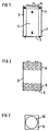
- FIG. 6 shows a capacitor housing 2 with cooling elements 16 which are designed for horizontal ventilation.
- the cooling elements 16 are square or hexagonal in shape and thus only require the otherwise unused gaps in a capacitor bank.
- FIG. 7 shows a further capacitor housing 2, which is provided with cooling elements 18 in a box shape without a base or lid and is suitable for vertical flow.
- FIG. 8 shows various temperature distributions of a capacitor with the nominal data 4000 ⁇ F / 350 V, which is installed in a housing measuring 0 ⁇ 75 mm x 145 mm.
- FIG. 8 a calculated temperature distribution for a capacitor according to FIG. 6 is shown in broken lines in FIG. 8, in which the cooling effect is greater than in the exemplary embodiments according to FIG.
Landscapes
- Engineering & Computer Science (AREA)
- Power Engineering (AREA)
- Microelectronics & Electronic Packaging (AREA)
- Cooling Or The Like Of Electrical Apparatus (AREA)
- Inverter Devices (AREA)
- Rectifiers (AREA)
Claims (11)
- Condensateur électrolytique susceptible de supporter une haute tension alternative, qui est logé dans un boîtier métallique pourvu d'éléments de refroidissement et qui est destiné à fonctionner avec un refroidissement forcé s'effectuant grâce à de l'air soufflé,
caractérisé en ce que les éléments de refroidissement (7) sont situés seulement dans des zones du boîtier (2) qui sont reliées au lieu de production de chaleur, le bobinage du condensateur (1), par un pont thermique (5, 6). - Condensateur électrolytique selon la revendication 1, caractérisé en ce que les éléments de refroidissement (7) sont formés par un ressort spiral (8) fait d'un matériau à bonne conductibilité thermique qui est passé sur le boîtier (1).
- Condensateur électrolytique selon la revendication 2, caractérisé en ce que le ressort spiral (8) est formé par un fil à section transversale ronde.
- Condensateur électrolytique selon la revendication 2, caractérisé en ce que le ressort spiral (8) est formé par un fil ayant une section transversale aplatie sur un côté qui est située sur le boîtier (2).
- Condensateur électrolytique selon la revendication 1, caractérisé en ce que les éléments de refroidissement sont formés par des tôles de refroidissement (9, 11) découpées.
- Condensateur électrolytique selon la revendication 5, caractérisé en ce que les tôles de refroidissement (9, 11) ont une forme carrée.
- Condensateur électrolytique selon la revendication 5, caractérisé en ce que les tôles de refroidissement ont une forme hexagonale.
- Condensateur électrolytique selon la revendication 1, caractérisé en ce que les tôles de refroidissement ont la forme d'une tôle ondulée (14).
- Condensateur électrolytique selon l'une des revendications 5 à 8, caractérisé en ce que les tôles de refroidissement (9, 11, 14) sont disposées sur le boîtier grâce à un ajustage serré.
- Condensateur électrolytique selon l'une des revendications 5 à 8, caractérisé en ce que les tôles de refroidissement (9, 11, 14) sont disposées sur le boîtier grâce à des forces élastiques.
- Condensateur électrolytique selon la revendication 10, caractérisé en ce que, pour obtenir la force élastique, le diamètre intérieur (10) de l'élément de refroidissement (11) est légèrement inférieur au diamètre extérieur du boîtier (1) et en ce que l'élément de refroidissement (11) est pourvu d'une fente (12) sur un côté.
Applications Claiming Priority (2)
| Application Number | Priority Date | Filing Date | Title |
|---|---|---|---|
| DE9213103U | 1992-09-29 | ||
| DE9213103U DE9213103U1 (de) | 1992-09-29 | 1992-09-29 | Elektrolytkondensator für hohe Wechselstrombelastbarkeit |
Publications (2)
| Publication Number | Publication Date |
|---|---|
| EP0591664A1 EP0591664A1 (fr) | 1994-04-13 |
| EP0591664B1 true EP0591664B1 (fr) | 1997-07-02 |
Family
ID=6884267
Family Applications (1)
| Application Number | Title | Priority Date | Filing Date |
|---|---|---|---|
| EP93113524A Expired - Lifetime EP0591664B1 (fr) | 1992-09-29 | 1993-08-24 | Condensateur électrolytique susceptible de supporter une haute tension alternative |
Country Status (3)
| Country | Link |
|---|---|
| EP (1) | EP0591664B1 (fr) |
| DE (2) | DE9213103U1 (fr) |
| ES (1) | ES2104010T3 (fr) |
Families Citing this family (3)
| Publication number | Priority date | Publication date | Assignee | Title |
|---|---|---|---|---|
| DE19817493C1 (de) * | 1998-04-20 | 1999-08-26 | Siemens Matsushita Components | Aluminium-Elektrolytkondensator |
| CN1875671A (zh) * | 2003-10-31 | 2006-12-06 | 西门子公司 | 具有集成冷却体的电子元件罩杯 |
| DE102011081283A1 (de) * | 2011-08-19 | 2013-02-21 | Robert Bosch Gmbh | Kondensator mit einem Kühlkörper |
Family Cites Families (4)
| Publication number | Priority date | Publication date | Assignee | Title |
|---|---|---|---|---|
| DE869509C (de) * | 1945-05-05 | 1953-03-05 | Asea Ab | Behaelter fuer elektrische Kondensatoren |
| DE3800641A1 (de) * | 1988-01-12 | 1989-07-20 | Siemens Ag | Aluminium-elektrolytkondensator und verfahren zu seiner herstellung |
| JP3099372B2 (ja) * | 1990-12-25 | 2000-10-16 | 松下電器産業株式会社 | アルミ電解コンデンサ |
| DE9203739U1 (de) * | 1992-03-19 | 1992-05-27 | Facon S.p.A. Fabbrica Condensatori Elettrici, Varese | Gehäuse für elektrische Kondensatoren |
-
1992
- 1992-09-29 DE DE9213103U patent/DE9213103U1/de not_active Expired - Lifetime
-
1993
- 1993-08-24 DE DE59306837T patent/DE59306837D1/de not_active Expired - Fee Related
- 1993-08-24 EP EP93113524A patent/EP0591664B1/fr not_active Expired - Lifetime
- 1993-08-24 ES ES93113524T patent/ES2104010T3/es not_active Expired - Lifetime
Also Published As
| Publication number | Publication date |
|---|---|
| DE9213103U1 (de) | 1992-11-12 |
| DE59306837D1 (de) | 1997-08-07 |
| EP0591664A1 (fr) | 1994-04-13 |
| ES2104010T3 (es) | 1997-10-01 |
Similar Documents
| Publication | Publication Date | Title |
|---|---|---|
| DE112017006112B4 (de) | Elektronische Steuerungsvorrichtung | |
| EP0051315A2 (fr) | Ensemble d'éléments semi-conducteurs | |
| DE2532772A1 (de) | Plattenspeicher-laufwerkeinheit | |
| EP0591664B1 (fr) | Condensateur électrolytique susceptible de supporter une haute tension alternative | |
| EP0389664A1 (fr) | Condensateur électrique, en particulier condensateur électrolytique enroulé | |
| DE4129547C2 (de) | Cryostat | |
| EP1080478B1 (fr) | Condensateur electrolytique en aluminium | |
| DE69601545T2 (de) | Vorrichtung zum Filtern eines elektrisch isolierenden und wärmeleitenden Flüssigkeitsmediums und damit ausgerüstete Leistungselektronikbaugruppe | |
| DE69100740T2 (de) | Luftheizungsgerät und Heizungszusammenbau. | |
| EP0162144A1 (fr) | Procédé de fabrication d'un condensateur électrique avec un diélectrique en polyéthylènetéréphtalate, en particulier utilisé comme élément pastille soudable | |
| EP0666627A1 (fr) | Dispositif absorbant des arcs électriques | |
| DE468482C (de) | Kondensator-Anordnung, bestehend aus in ein Gehaeuse eingebauten elektrischen Kondensatoren mit steifen dielektrischen Platten, insbesondere Glimmerkondensatoren | |
| DE3805005C2 (fr) | ||
| CH684724A5 (de) | Elektrische Anlage für ein Mittel- oder Niederspannungsnetz, insbesondere zur Kompensation von Blindleistung und/oder zum Absaugen harmonischer Oberschwingungen. | |
| DE1464641A1 (de) | Elektrische Vorrichtung mit Kuehlanordnung | |
| EP0030738A1 (fr) | Support pour ballast de lampes fluorescentes | |
| DE2500223C3 (de) | Elektrisches Widerstandsgerät | |
| EP4136937B1 (fr) | Résistance de freinage et véhicule équipé de celle-ci | |
| DE10236525A1 (de) | Ventilbautelement-Satz in Zweigpaar-Konfiguration für einen elektrischen Wechselrichter | |
| EP0072478B1 (fr) | Redresseur à haute tension | |
| DE2714373A1 (de) | Wechselstromgenerator | |
| DE918998C (de) | Kondensator, dessen aeussere Gefaesswand als ableitende Kuehlplatte dient | |
| DE656392C (de) | Zuendspule | |
| DE3610219A1 (de) | Trockenkondensator mit verbesserter druckgesteuerter unterbrechersicherung | |
| DE4400105C2 (de) | Gehäusewiderstand |
Legal Events
| Date | Code | Title | Description |
|---|---|---|---|
| PUAI | Public reference made under article 153(3) epc to a published international application that has entered the european phase |
Free format text: ORIGINAL CODE: 0009012 |
|
| AK | Designated contracting states |
Kind code of ref document: A1 Designated state(s): DE ES FR GB IT SE |
|
| 17P | Request for examination filed |
Effective date: 19941006 |
|
| 17Q | First examination report despatched |
Effective date: 19951004 |
|
| GRAG | Despatch of communication of intention to grant |
Free format text: ORIGINAL CODE: EPIDOS AGRA |
|
| GRAH | Despatch of communication of intention to grant a patent |
Free format text: ORIGINAL CODE: EPIDOS IGRA |
|
| GRAH | Despatch of communication of intention to grant a patent |
Free format text: ORIGINAL CODE: EPIDOS IGRA |
|
| GRAH | Despatch of communication of intention to grant a patent |
Free format text: ORIGINAL CODE: EPIDOS IGRA |
|
| GRAA | (expected) grant |
Free format text: ORIGINAL CODE: 0009210 |
|
| AK | Designated contracting states |
Kind code of ref document: B1 Designated state(s): DE ES FR GB IT SE |
|
| REF | Corresponds to: |
Ref document number: 59306837 Country of ref document: DE Date of ref document: 19970807 |
|
| ET | Fr: translation filed | ||
| ITF | It: translation for a ep patent filed | ||
| GBT | Gb: translation of ep patent filed (gb section 77(6)(a)/1977) |
Effective date: 19970903 |
|
| REG | Reference to a national code |
Ref country code: ES Ref legal event code: FG2A Ref document number: 2104010 Country of ref document: ES Kind code of ref document: T3 |
|
| PLBE | No opposition filed within time limit |
Free format text: ORIGINAL CODE: 0009261 |
|
| 26N | No opposition filed | ||
| REG | Reference to a national code |
Ref country code: GB Ref legal event code: IF02 |
|
| PGFP | Annual fee paid to national office [announced via postgrant information from national office to epo] |
Ref country code: GB Payment date: 20050817 Year of fee payment: 13 Ref country code: FR Payment date: 20050817 Year of fee payment: 13 |
|
| PGFP | Annual fee paid to national office [announced via postgrant information from national office to epo] |
Ref country code: SE Payment date: 20050819 Year of fee payment: 13 |
|
| PGFP | Annual fee paid to national office [announced via postgrant information from national office to epo] |
Ref country code: ES Payment date: 20050826 Year of fee payment: 13 |
|
| PGFP | Annual fee paid to national office [announced via postgrant information from national office to epo] |
Ref country code: DE Payment date: 20050930 Year of fee payment: 13 |
|
| PG25 | Lapsed in a contracting state [announced via postgrant information from national office to epo] |
Ref country code: SE Free format text: LAPSE BECAUSE OF NON-PAYMENT OF DUE FEES Effective date: 20060825 |
|
| PGFP | Annual fee paid to national office [announced via postgrant information from national office to epo] |
Ref country code: IT Payment date: 20060831 Year of fee payment: 14 |
|
| PG25 | Lapsed in a contracting state [announced via postgrant information from national office to epo] |
Ref country code: DE Free format text: LAPSE BECAUSE OF NON-PAYMENT OF DUE FEES Effective date: 20070301 |
|
| EUG | Se: european patent has lapsed | ||
| GBPC | Gb: european patent ceased through non-payment of renewal fee |
Effective date: 20060824 |
|
| REG | Reference to a national code |
Ref country code: FR Ref legal event code: ST Effective date: 20070430 |
|
| REG | Reference to a national code |
Ref country code: ES Ref legal event code: FD2A Effective date: 20060825 |
|
| PG25 | Lapsed in a contracting state [announced via postgrant information from national office to epo] |
Ref country code: GB Free format text: LAPSE BECAUSE OF NON-PAYMENT OF DUE FEES Effective date: 20060824 |
|
| PG25 | Lapsed in a contracting state [announced via postgrant information from national office to epo] |
Ref country code: ES Free format text: LAPSE BECAUSE OF NON-PAYMENT OF DUE FEES Effective date: 20060825 |
|
| PG25 | Lapsed in a contracting state [announced via postgrant information from national office to epo] |
Ref country code: FR Free format text: LAPSE BECAUSE OF NON-PAYMENT OF DUE FEES Effective date: 20060831 |
|
| PG25 | Lapsed in a contracting state [announced via postgrant information from national office to epo] |
Ref country code: IT Free format text: LAPSE BECAUSE OF NON-PAYMENT OF DUE FEES Effective date: 20070824 |