EP0591677B1 - Kühlanlage für Brennkraftmaschine - Google Patents
Kühlanlage für Brennkraftmaschine Download PDFInfo
- Publication number
- EP0591677B1 EP0591677B1 EP93113857A EP93113857A EP0591677B1 EP 0591677 B1 EP0591677 B1 EP 0591677B1 EP 93113857 A EP93113857 A EP 93113857A EP 93113857 A EP93113857 A EP 93113857A EP 0591677 B1 EP0591677 B1 EP 0591677B1
- Authority
- EP
- European Patent Office
- Prior art keywords
- engine
- catalyst
- cooling system
- engine cooling
- radiator
- Prior art date
- Legal status (The legal status is an assumption and is not a legal conclusion. Google has not performed a legal analysis and makes no representation as to the accuracy of the status listed.)
- Expired - Lifetime
Links
Images


Classifications
-
- B—PERFORMING OPERATIONS; TRANSPORTING
- B60—VEHICLES IN GENERAL
- B60K—ARRANGEMENT OR MOUNTING OF PROPULSION UNITS OR OF TRANSMISSIONS IN VEHICLES; ARRANGEMENT OR MOUNTING OF PLURAL DIVERSE PRIME-MOVERS IN VEHICLES; AUXILIARY DRIVES FOR VEHICLES; INSTRUMENTATION OR DASHBOARDS FOR VEHICLES; ARRANGEMENTS IN CONNECTION WITH COOLING, AIR INTAKE, GAS EXHAUST OR FUEL SUPPLY OF PROPULSION UNITS IN VEHICLES
- B60K11/00—Arrangement in connection with cooling of propulsion units
- B60K11/02—Arrangement in connection with cooling of propulsion units with liquid cooling
- B60K11/04—Arrangement or mounting of radiators, radiator shutters, or radiator blinds
-
- F—MECHANICAL ENGINEERING; LIGHTING; HEATING; WEAPONS; BLASTING
- F01—MACHINES OR ENGINES IN GENERAL; ENGINE PLANTS IN GENERAL; STEAM ENGINES
- F01N—GAS-FLOW SILENCERS OR EXHAUST APPARATUS FOR MACHINES OR ENGINES IN GENERAL; GAS-FLOW SILENCERS OR EXHAUST APPARATUS FOR INTERNAL-COMBUSTION ENGINES
- F01N3/00—Exhaust or silencing apparatus having means for purifying, rendering innocuous, or otherwise treating exhaust
- F01N3/08—Exhaust or silencing apparatus having means for purifying, rendering innocuous, or otherwise treating exhaust for rendering innocuous
- F01N3/10—Exhaust or silencing apparatus having means for purifying, rendering innocuous, or otherwise treating exhaust for rendering innocuous by thermal or catalytic conversion of noxious components of exhaust
- F01N3/18—Exhaust or silencing apparatus having means for purifying, rendering innocuous, or otherwise treating exhaust for rendering innocuous by thermal or catalytic conversion of noxious components of exhaust characterised by methods of operation; Control
- F01N3/20—Exhaust or silencing apparatus having means for purifying, rendering innocuous, or otherwise treating exhaust for rendering innocuous by thermal or catalytic conversion of noxious components of exhaust characterised by methods of operation; Control specially adapted for catalytic conversion
- F01N3/2006—Periodically heating or cooling catalytic reactors, e.g. at cold starting or overheating
-
- F—MECHANICAL ENGINEERING; LIGHTING; HEATING; WEAPONS; BLASTING
- F01—MACHINES OR ENGINES IN GENERAL; ENGINE PLANTS IN GENERAL; STEAM ENGINES
- F01P—COOLING OF MACHINES OR ENGINES IN GENERAL; COOLING OF INTERNAL-COMBUSTION ENGINES
- F01P3/00—Liquid cooling
- F01P3/18—Arrangements or mounting of liquid-to-air heat-exchangers
-
- B—PERFORMING OPERATIONS; TRANSPORTING
- B60—VEHICLES IN GENERAL
- B60K—ARRANGEMENT OR MOUNTING OF PROPULSION UNITS OR OF TRANSMISSIONS IN VEHICLES; ARRANGEMENT OR MOUNTING OF PLURAL DIVERSE PRIME-MOVERS IN VEHICLES; AUXILIARY DRIVES FOR VEHICLES; INSTRUMENTATION OR DASHBOARDS FOR VEHICLES; ARRANGEMENTS IN CONNECTION WITH COOLING, AIR INTAKE, GAS EXHAUST OR FUEL SUPPLY OF PROPULSION UNITS IN VEHICLES
- B60K13/00—Arrangement in connection with combustion air intake or gas exhaust of propulsion units
- B60K13/04—Arrangement in connection with combustion air intake or gas exhaust of propulsion units concerning exhaust
-
- F—MECHANICAL ENGINEERING; LIGHTING; HEATING; WEAPONS; BLASTING
- F01—MACHINES OR ENGINES IN GENERAL; ENGINE PLANTS IN GENERAL; STEAM ENGINES
- F01N—GAS-FLOW SILENCERS OR EXHAUST APPARATUS FOR MACHINES OR ENGINES IN GENERAL; GAS-FLOW SILENCERS OR EXHAUST APPARATUS FOR INTERNAL-COMBUSTION ENGINES
- F01N13/00—Exhaust or silencing apparatus characterised by constructional features
- F01N13/08—Other arrangements or adaptations of exhaust conduits
- F01N13/10—Other arrangements or adaptations of exhaust conduits of exhaust manifolds
-
- F—MECHANICAL ENGINEERING; LIGHTING; HEATING; WEAPONS; BLASTING
- F01—MACHINES OR ENGINES IN GENERAL; ENGINE PLANTS IN GENERAL; STEAM ENGINES
- F01N—GAS-FLOW SILENCERS OR EXHAUST APPARATUS FOR MACHINES OR ENGINES IN GENERAL; GAS-FLOW SILENCERS OR EXHAUST APPARATUS FOR INTERNAL-COMBUSTION ENGINES
- F01N2260/00—Exhaust treating devices having provisions not otherwise provided for
- F01N2260/02—Exhaust treating devices having provisions not otherwise provided for for cooling the device
-
- F—MECHANICAL ENGINEERING; LIGHTING; HEATING; WEAPONS; BLASTING
- F01—MACHINES OR ENGINES IN GENERAL; ENGINE PLANTS IN GENERAL; STEAM ENGINES
- F01P—COOLING OF MACHINES OR ENGINES IN GENERAL; COOLING OF INTERNAL-COMBUSTION ENGINES
- F01P11/00—Component parts, details, or accessories not provided for in, or of interest apart from, groups F01P1/00 - F01P9/00
- F01P11/10—Guiding or ducting cooling-air, to, or from, liquid-to-air heat exchangers
-
- Y—GENERAL TAGGING OF NEW TECHNOLOGICAL DEVELOPMENTS; GENERAL TAGGING OF CROSS-SECTIONAL TECHNOLOGIES SPANNING OVER SEVERAL SECTIONS OF THE IPC; TECHNICAL SUBJECTS COVERED BY FORMER USPC CROSS-REFERENCE ART COLLECTIONS [XRACs] AND DIGESTS
- Y02—TECHNOLOGIES OR APPLICATIONS FOR MITIGATION OR ADAPTATION AGAINST CLIMATE CHANGE
- Y02A—TECHNOLOGIES FOR ADAPTATION TO CLIMATE CHANGE
- Y02A50/00—TECHNOLOGIES FOR ADAPTATION TO CLIMATE CHANGE in human health protection, e.g. against extreme weather
- Y02A50/20—Air quality improvement or preservation, e.g. vehicle emission control or emission reduction by using catalytic converters
-
- Y—GENERAL TAGGING OF NEW TECHNOLOGICAL DEVELOPMENTS; GENERAL TAGGING OF CROSS-SECTIONAL TECHNOLOGIES SPANNING OVER SEVERAL SECTIONS OF THE IPC; TECHNICAL SUBJECTS COVERED BY FORMER USPC CROSS-REFERENCE ART COLLECTIONS [XRACs] AND DIGESTS
- Y02—TECHNOLOGIES OR APPLICATIONS FOR MITIGATION OR ADAPTATION AGAINST CLIMATE CHANGE
- Y02T—CLIMATE CHANGE MITIGATION TECHNOLOGIES RELATED TO TRANSPORTATION
- Y02T10/00—Road transport of goods or passengers
- Y02T10/10—Internal combustion engine [ICE] based vehicles
- Y02T10/12—Improving ICE efficiencies
Definitions
- This invention relates to an engine cooling system for a front engine vehicle by means of a radiator and airstreams induced by a radiator fan and by the motion of the automobile.
- a front engine vehicle directly induces a stream of cold air to its engine body by its motion. Furthermore, the engine is indirectly cooled by a radiator positioned in front of the engine, through which water is conducted, and across which airstreams are induced by a fan.
- the vehicle When running at a speed above a preset value, such a front engine vehicle can sufficiently induce a cold airstream to cool its engine. Conversely, when running at a very low speed or when out of motion, the vehicle cannot induce a cold airstream to the engine body, which leaves the engine hot.
- the vehicle is usually equipped with a fan between the radiator and the engine. The fan is operated by the rotational force of the engine, or by a motor. In this arrangement, the fan conducts a cold airstream to the engine and the radiator so as to reliably cool the engine body.
- a control unit for such a vehicle engine selects a suitable operation mode based on various engine operation data. For instance, when the partial cylinder operation mode is selected, the control unit provides a variable valve operating mechanism with a command for this mode. In response to the command, the variable valve operating mechanism interrupts the operation of intake and exhaust valves associated with the cylinders to be disconnected. In addition, the control unit sends this command to a fuel supply system, which suspends the fuel supply to the disconnected cylinders. In the partial cylinder operation mode, the engine produces fewer thermal energies than those in the full cylinder operation mode. Therefore, exhaust emissions are efficiently heat-radiated in a exhaust pipe, so that they tend to be extensively cooled.
- the engine exhaust emissions usually include noxious substances such as carbon monoxide CO, hydrocarbons HC, and nitrogen oxides NOx.
- the exhaust emissions should be free from these substances when they are discharged into the atmosphere.
- three-way catalysts are disposed in the exhaust system of a popular gasoline-fueled engine so as to remove CO, HC and NOx from the exhaust emissions.
- a diesel engine includes the three-way catalyst so as to purify nitrogen oxides NOx.
- the three-way catalyst has to be at its active temperature where it can effectively reduce and oxidize CO, HC and NOx so as to make these substance nontoxic, as shown in Fig. 5 of the accompanying drawings.
- Fig. 5 shows purification efficiencies of the three-way catalyst of a platinum group, which is used in a gasoline-fueled engine operating at a speed of 2400 rpm and an intake air pressure of -300 mmHg. The air-fuel ratio is maintained between 14.6 and 14.7. It can be seen that the purification efficiency of 50% can be attained for each of CO, HC and NOx when the exhaust emissions are in the temperature range of 340°C to 350°C (e.g. the efficient and active temperature). It is known that the reduction catalyst becomes active to reduce NOx when the exhaust emissions have the foregoing temperature.
- the exhaust emissions extensively vary their temperature according to the operating conditions of the engine, airstreams induced by the motion of the vehicle, heat radiation from an exhaust manifold cooled by airstreams from the radiator fan, ambient temperature, and so on.
- the temperature of the exhaust emissions tends to become low at the time of engine start-up, a low output, or a low ambient temperature. If heat-radiation is enhanced from the exhaust manifold which is cooled by airstreams induced by the motion of the vehicle and by the radiator fan, it is very difficult to keep the exhaust emissions sufficiently hot to activate the catalyst. Therefore, when activated at the initial stage of engine start-up, the three-way catalyst, a NOx catalyst, or a small front catalyst near a combustion chamber cannot oxide or reduce CO, HC and NOx in the exhaust emissions so as to make these substances substantially nontoxic. This would cause serious pollution of the atmosphere.
- the exhaust emissions have a low temperature when the engine in the partial cylinder operation mode produces fewer thermal energies. Specifically, when the heat-radiation of the exhaust manifold is enhanced by airstreams induced by the radiator fan or by the motion of the vehicle, the exhaust emissions become further cold. Therefore, the catalyst cannot attain its effective temperature to eliminate CO, HD and NOx from the exhaust emissions. This phenomen would also cause serious pollution of the atmosphere.
- US Patent No. 3,820,327 discloses a temperature regulator applicable to overcoming a problem that a temperature of the catalyst reactor is lowered by induced air flow.
- the system comprises a fan 5 actuated by the vehicle engine, a radiator 4 disposed before the engine, a casing 6 surrounding the fan 5 and circulating cooling air induced by the fan 5, a casing 8 housing a catalyst reactor 1, a flap 9 disposed at an entrance of the casing 8 so as to regulate a flow of cooling air, and a link-rod system 10 for opening and closing the flap 9.
- the flap 9 When cold-starting is effected, the flap 9 is in the closed position so as to close the casing 8, so cooling air will be released into the atmosphere through an aperture 11, thereby preventing the catalyst reactor 1 from becoming too cold. Under the full running load, the aperture will be closed by the flap 9 such that cooling air will be circulated to the casing 8 so as to prevent the catalyst reactor 1 from becoming too hot.
- the cooling system requires not only a lot of components such as the casings 6 and 8, flap 9 and link-rod system 10 dedicated thereto but also spaces for disposing the casings 6 and 8 in the engine room. This means that only a limited space is available for auxiliary devices to be installed in the engine room, and that the engine room should be designed considering a number of restrictive factors.
- Fig. 1 is a schematic top plan view showing the configuration of a first engine cooling system for a front engine vehicle having the partial cylinder operation function.
- Fig. 2 is a side cross-sectional view of the vehicle of Fig. 1.
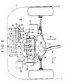
- Fig. 3 is an enlarged schematic view showing the main part of the cooling system of Fig. 1.
- Fig. 4 is a schematic view of a second engine cooling system for the front engine vehicle having the partial cylinder operation function.
- Fig. 5 is a graph showing purification efficiencies of a three-way catalyst.
- an engine cooling system is applied to an engine 3 which is used for a vehicle of the front drive wheel type and has the partial cylinder operation mode.
- the engine cooling system is disposed in an engine room 2 at the front part of a vehicle body 1.
- the engine 3 is an in-line horizontal engine having four cylinders.
- a radiator 4 is positioned in front of the engine 3 in the direction X shown in Fig. 1.
- the engine 3 is installed on a main frame (not shown) of the vehicle body with its engine body 5 oriented in the direction Y.
- the engine body 5 accompanies an exhaust manifold 7 at its front side and an intake manifold 7 at its rear side.
- the intake manifold 7 is coupled to an intake pipe 8 and an air cleaner 9 in this order.
- the exhaust manifold 6 communicates with a front catalyst 10 and an exhaust pipe 11.
- the exhaust pipe 11 extends to a main catalyst 12 and reaches a muffler 13.
- the front catalyst 10 is positioned just under the exhaust manifold 6, while the main catalyst is positioned in the middle of the exhaust pipe 11.
- the front catalyst 10 is a well-known oxidation catalyst while the main catalyst 12 is a well-known three-way catalyst.
- the front catalyst 10 has a relatively small capacity so that it becomes active at an initial stage of the engine start-up period, and can effectively purify the exhaust emissions during this period.
- the main catalyst 12 comprises noble metal such as platinum. When elevated above the effective temperature, the main catalyst 12 can effectively eliminate carbon monoxide CO, hydrocarbons HC and nitrogen oxides NOx from the exhaust emissions of the air-fuel mixture having a ratio near the stoichiometric ratio.
- the front catalyst 10 may be the three-way catalyst.
- the cylinders #2 and #3 are continuously active while the cylinders #1 and #4 remain inactive in the engine 3.
- the exhaust ports (not shown) of the cylinders #1 and #2 merge while the exhaust ports (not shown) of the cylinders #3 and #4 merge as shown in Fig. 3.
- These exhaust ports are coupled to two points 111 of forked end of the exhaust pipe 11, so that the exhaust emissions flow through the exhaust pipe 11 to reach the front catalyst 10.
- the engine 3 includes, in its valve operating system, a variable valve operating mechanism M for selectively operating the intake and exhaust valves.
- the variable valve operating mechanism M is controlled by a hydraulic switching circuit 14, which is controlled by a controller 15.
- the controller 15 When the full cylinder operation mode is selected, the controller 15 turns off the variable valve operating mechanism M, i.e. controls the mechanism M via the hydraulic switching circuit 14 in a manner such that the cylinders #1 to #4 are active. Further, the controller 15 provides the fuel supply system with the command for the full cylinder operation mode. In response to this command, the fuel supply system supplies fuel to all the four cylinders.
- the controller 15 turns on the variable valve operating mechanism M, i.e. controls the mechanism M so as to operate only the cylinders #2 and #3 and disconnect the cylinders #1 and #4 via the hydraulic switching circuit 14. Further, the controller 15 provides the fuel supply system with the partial cylinder operation command, so that fuel is supplied only to the cylinders #2 and #3 via their associated injectors (not shown).
- the variable valve operating mechanism M is described in the co-pending Japanese patent application No. Hei 2-182131 entitled VALVE SYSTEM FOR MOTOR VEHICLE filed on July 10, 1990 (laid open under No. 4-72403).
- the radiator 4 is placed in front of the engine 3 in the engine room 2.
- the radiator 4 communicates with a water jacket (not shown) of the engine body 5 so as to circulate the cooling water thereto.
- a warmed cooling water is cooled by airstreams a (induced by the radiator fan, and called “radiator airstreams a " hereinafter) and airstreams b (induced by the motion of the vehicle, and called “incoming airstreams b " hereinafter).
- the radiator 4 has a width B1 across the vehicle body in the direction Y, and is shaped to cover the front areas of the engine body 5, a clutch 16 and a transmission 17.
- the radiator 4 is substantially as high as the engine body 5 as shown by B2 in Fig. 2.
- a radiator fan 18 is positioned behind the radiator 4.
- the radiator fan 18 leads cold airstreams via the radiator 4 toward the engine 3.
- a fan shroud 19 is disposed to surround the radiator fan 18 so as to guide the cold airstreams.
- the radiator fan 18 and a fan motor 20 are supported at the center of the shroud by suitable brackets 21.
- the motor 20 is controlled by the controller 15.
- the shroud 19 is placed only on the right half area of the radiator 4 (Figs. 1 and 3), i.e. the shroud is placed in a manner such that the center of the radiator fan 18 is offset by the distance S from the front center of the exhaust manifold 6. Therefore, when the radiator fan 18 is active, the radiator airstreams a are guided by the shroud 19 toward the clutch 16 and the transmission 17 but do not touch the exhaust manifold 6 of the engine body 5 as shown in Fig. 3. It is possible to place a heat exchanger for an air-conditioner in front of the radiator 4 at a position (shown by long and short dash lines) opposite to the radiator fan 18 as shown in Figs. 1 and 2.
- the radiator fan 18 In operation, when the engine 3 undergoes a cold start, the radiator fan 18 remains inactive.
- the controller 15 actuates the radiator fan 18 at a proper timing after the completion of the cold start period of the engine. Thereafter, the radiator airstreams a are guided by the fan 18 via the shroud 19 toward the clutch 16 and the transmission 17, but do not directly flow toward the exhaust manifold 6 and the outer wall of the front catalyst 10 which is just under the exhaust manifold 10.
- the engine 3 is set in the partial cylinder operation mode under this condition, so that the total energies produced by the engine are accordingly reduced, which causes the exhaust emissions to be lower in their temperature. Since the radiator airstreams a are however made to flow wide of the exhaust manifold 6, the exhaust emissions are not further lowered in their temperature. Therefore, both the front catalyst 10 and the main catalyst 12 become active during the engine start-up period and can remain active to eliminate noxious substances effectively from the exhaust emissions.
- radiator airstreams a are conducted to the clutch 16 and the transmission 17.
- the engine is operating at a very low load or is idling in the partial cylinder operation mode under this condition, so that it produces relatively low energies. Since radiator airstreams a do not directly flow to the exhaust manifold 6 and the outer wall of the front catalyst 10, the exhaust emission flowing through the exhaust manifold 6 are not excessively lowered in their temperature. Thus, both the front catalyst 10 and the main catalyst can function effectively and reliably.
- the cooling system is applied to an in-line vertical four-cylinder engine with the partial cylinder operation mode.
- This engine 3 includes its crankshaft extending perpendicular to the axle, and the intake manifold 7 which is placed behind the radiator fan 18 and extends to the air cleaner 9.
- the exhaust manifold 6 extends to the main catalyst 12, and is attached to the engine body 5 at a position which is displaced by the distance S1 from a position which is displaced by the distance 51 from the axis of the radiator fan motor.
- radiator airstreams a are guided by the fan shroud 19 to flow toward the intake manifold 7.
- the cooling system is effectively applicable to the in-line vertical engine similarly to the cooling systems of the foregoing embodiment.
- the radiator fan is positioned in front of the engine in a manner such that the radiator airstreams do not directly strike the exhaust manifold of the engine.
- the exhaust emissions flowing through the exhaust manifold are prevented from being excessively cooled by the radiator airstreams, thereby allowing the catalysts to be active to eliminate noxious substances from the exhaust emissions.
- the front catalyst 10 is disposed just under the exhaust manifold 6 and the main catalyst 12 follows downstream of the front catalyst 10.
- a NOx catalyst may be placed downstream of the exhaust manifold of a diesel engine and the radiator fan may be positioned in front of the exhaust manifold with a certain distance displaced from the front part of the exhaust manifold.
- the engine 3 includes the variable valve operating mechanism M in its valve system.
- the control unit 15 issues the command for the partial cylinder operation mode
- the variable valve operating mechanism M activates the valve system accordingly.
- the fuel supply system provides the active cylinders with fuel in response to the foregoing command.
- the present invention is effectively applicable to ordinary engines which do not have the partial cylinder operation mode.
Landscapes
- Engineering & Computer Science (AREA)
- Chemical & Material Sciences (AREA)
- Combustion & Propulsion (AREA)
- Mechanical Engineering (AREA)
- General Engineering & Computer Science (AREA)
- Chemical Kinetics & Catalysis (AREA)
- Transportation (AREA)
- Health & Medical Sciences (AREA)
- Toxicology (AREA)
- Exhaust Gas After Treatment (AREA)
- Cooling, Air Intake And Gas Exhaust, And Fuel Tank Arrangements In Propulsion Units (AREA)
Claims (11)
- Motorkühlsystem für einen Motor (3) mit einem Katalysator, der stromabwärts eines Auspuffkrümmers (6) angeordnet ist, und das einen Kühler (4) umfaßt, der vor dem Motor (3) angeordnet ist, sowie einen Kühlerventilator (18), der einen Luftstrom von einem vorderen Teil des Fahrzeugs zu einem hinteren Teil desselben einführt, dadurch gekennzeichnet, daß der Kühlerventilator (18) an einer Stelle angeordnet ist, die von einer Vorderseite des Auspuffkrümmers (6) derart versetzt ist, daß die eingeleiteten Luftströme nicht direkt in Richtung des Auspuffkrümmers (6) strömen, wodurch die Abgasemissionen heiß gehalten werden.
- Motorkühlsystem nach Anspruch 1, wobei der Katalysator ein erster Katalysator (10) ist, der genau unter dem Auspuffkrümmer (7) angeordnet ist.
- Motorkühlsystem nach Anspruch 2, wobei der erste Katalysator (10) ein Oxidationskatalysator ist.
- Motorkühlsystem nach Anspruch 2, wobei der erste Katalysator (10) ein Dreiwegkatalysator ist.
- Motorkühlsystem nach Anspruch 1, wobei der Motor (3) ein Horizontalmotor mit einer Kurbelwelle ist, die parallel zu einer Achse axial angeordnet ist.
- Motorkühlsystem nach Anspruch 5, wobei der Auspuffkrümmer (7) vor dem Motor (3) angeordnet ist.
- Motorkühlsystem nach Anspruch 1, wobei der Katalysator ein zweiter Katalysator (12) ist, der in der Mitte einer Auspuffleitung (11) angeordnet ist.
- Motorkühlsystem nach Anspruch 7, wobei der zweite Katalysator (12) ein Dreiwegkatalysator ist.
- Motorkühlsystem nach Anspruch 1, wobei der Motor (3) ein Vertikalmotor mit einer Kurbelwelle ist, die in axialer Richtung senkrecht zu einer Achse angeordnet ist.
- Motorkühlsystem nach Anspruch 9, wobei der Auspuffkrümmer (7) mit dem Motor (3) auf einer dem Kühlerventilator (18) gegenüberliegenden Seite verbunden ist.
- Motorkühlsystem nach einem der Ansprüche 1 bis 10, wobei der Motor (3) ein Zylinderabschaltsystem enthält, um einige Motorzylinder in geeigneter Weise unbetätigt zu lassen.
Applications Claiming Priority (2)
| Application Number | Priority Date | Filing Date | Title |
|---|---|---|---|
| JP236920/92 | 1992-09-04 | ||
| JP4236920A JP2845048B2 (ja) | 1992-09-04 | 1992-09-04 | 休筒機構付きエンジンの冷却装置 |
Publications (2)
| Publication Number | Publication Date |
|---|---|
| EP0591677A1 EP0591677A1 (de) | 1994-04-13 |
| EP0591677B1 true EP0591677B1 (de) | 1996-11-13 |
Family
ID=17007711
Family Applications (1)
| Application Number | Title | Priority Date | Filing Date |
|---|---|---|---|
| EP93113857A Expired - Lifetime EP0591677B1 (de) | 1992-09-04 | 1993-08-30 | Kühlanlage für Brennkraftmaschine |
Country Status (6)
| Country | Link |
|---|---|
| US (1) | US5711387A (de) |
| EP (1) | EP0591677B1 (de) |
| JP (1) | JP2845048B2 (de) |
| KR (1) | KR960012126B1 (de) |
| AU (1) | AU661191B2 (de) |
| DE (1) | DE69305958T2 (de) |
Families Citing this family (19)
| Publication number | Priority date | Publication date | Assignee | Title |
|---|---|---|---|---|
| US6381347B1 (en) | 1998-11-12 | 2002-04-30 | Secugen | High contrast, low distortion optical acquistion system for image capturing |
| US6324020B1 (en) | 1999-08-04 | 2001-11-27 | Secugen Corporation | Method and apparatus for reduction of trapezoidal distortion and improvement of image sharpness in an optical image capturing system |
| US7121368B2 (en) * | 2000-05-09 | 2006-10-17 | Mackelvie Winston | Bi-directional automotive cooling fan |
| US6381953B1 (en) | 2000-12-07 | 2002-05-07 | Ford Global Technologies, Inc. | Exhaust gas oxygen sensor temperature control for a variable displacement engine |
| US6389806B1 (en) | 2000-12-07 | 2002-05-21 | Ford Global Technologies, Inc. | Variable displacement engine control for fast catalyst light-off |
| US6415601B1 (en) | 2000-12-07 | 2002-07-09 | Ford Global Technologies, Inc. | Temperature management of catalyst system for a variable displacement engine |
| DE10147624B4 (de) * | 2001-09-27 | 2012-07-19 | Volkswagen Ag | Abgaskühlvorrichtung für eine Brennkraftmaschine |
| JP4066741B2 (ja) * | 2002-08-22 | 2008-03-26 | 株式会社デンソー | 車両前端構造 |
| JP4280142B2 (ja) * | 2003-10-17 | 2009-06-17 | 川崎重工業株式会社 | 縦軸型液冷エンジン |
| JP4650261B2 (ja) * | 2005-12-28 | 2011-03-16 | スズキ株式会社 | 過給機付エンジンのインタークーラ配設構造 |
| DE102007013034B4 (de) * | 2006-04-08 | 2015-11-12 | Schaeffler Technologies AG & Co. KG | Kupplungskühlung |
| US20120012078A1 (en) * | 2010-07-14 | 2012-01-19 | John Carl Lohr | Intake manifold for internal combustion engine |
| CN106030069B (zh) | 2014-03-20 | 2019-05-03 | 洋马株式会社 | 发动机装置 |
| JP2015183546A (ja) * | 2014-03-20 | 2015-10-22 | ヤンマー株式会社 | エンジン装置 |
| GB2541920A (en) * | 2015-09-04 | 2017-03-08 | Jaguar Land Rover Ltd | System and method for cooling an electric vehicle |
| CN106741978B (zh) * | 2016-12-30 | 2023-09-29 | 重庆驼航科技有限公司 | 一种直升机用一体化复合式冷却系统 |
| US10239401B2 (en) * | 2017-01-23 | 2019-03-26 | Auburn Gear, Llc | Electric motor and gearing assembly |
| CN107869417A (zh) * | 2017-11-10 | 2018-04-03 | 中汽研(天津)汽车工程研究院有限公司 | 一种车辆发动机快速暖机系统 |
| CN108583473B (zh) * | 2018-04-13 | 2022-02-01 | 桂林航天工业学院 | 智能混合动力汽车、风扇冷却系统及方法 |
Family Cites Families (18)
| Publication number | Priority date | Publication date | Assignee | Title |
|---|---|---|---|---|
| FR2070468A5 (de) * | 1969-12-05 | 1971-09-10 | Nissan Motor | |
| GB1361910A (en) * | 1971-08-19 | 1974-07-30 | Ford Motor Co | Internal combustion engine having a catalytic converter for ex haust gases |
| US3820327A (en) * | 1972-05-10 | 1974-06-28 | Peugeot & Renault | Temperature regulator for a catalytic reactor |
| AT379434B (de) * | 1976-07-21 | 1986-01-10 | List Hans | Wassergekuehlte brennkraftmaschine zum antrieb von fahrzeugen, insbesondere dieselmotor |
| DE3322338A1 (de) * | 1982-07-01 | 1984-01-05 | AVL Gesellschaft für Verbrennungskraftmaschinen und Messtechnik mbH, Prof. Dr.Dr.H.C. Hans List, 8020 Graz | Kraftfahrzeug mit einer wassergekuehlten brennkraftmaschine als antriebsmotor |
| JPS62174516A (ja) * | 1986-01-29 | 1987-07-31 | Fuji Heavy Ind Ltd | 自動車用エンジンの動弁装置 |
| JPS62203913A (ja) * | 1986-02-28 | 1987-09-08 | Fuji Heavy Ind Ltd | 自動車用エンジンの動弁装置 |
| JPS62273113A (ja) * | 1986-05-20 | 1987-11-27 | Toyota Motor Corp | ラジエ−タとク−ラコンデンサの配置構造 |
| JPS63100211A (ja) * | 1986-10-15 | 1988-05-02 | Honda Motor Co Ltd | 内燃機関の動弁装置 |
| DE3800347A1 (de) * | 1987-01-08 | 1988-09-29 | Honda Motor Co Ltd | Ventilbetaetigungsvorrichtung in einer brennkraftmaschine |
| US4883027A (en) * | 1987-11-25 | 1989-11-28 | Honda Giken Kogyo Kabushiki Kaisha | Valve operating system for internal combustion engines |
| US5050701A (en) * | 1988-05-31 | 1991-09-24 | Yamaha Hatsudoki Kabushiki Kaisha | Engine manifolding and orientation for the engine compartment of a motor vehicle |
| US5195607A (en) * | 1989-11-21 | 1993-03-23 | Mazda Motor Corporation | Exhaust system for automotive engine |
| US5207187A (en) * | 1990-07-04 | 1993-05-04 | Kubota Corporation | Air cooling system for a vertical engine |
| KR950005088B1 (ko) * | 1990-07-10 | 1995-05-18 | 미쯔비시 지도샤 고교 가부시끼가이샤 | 자동차용 동력 밸브 장치 |
| US5209285A (en) * | 1990-09-24 | 1993-05-11 | General Motors Corporation | Inclined tube radiator |
| US5180003A (en) * | 1992-01-14 | 1993-01-19 | Caterpillar Inc. | Dual fan cooling system |
| US5193608A (en) * | 1992-03-25 | 1993-03-16 | Toyo Radiator Co., Ltd. | Radiator with fan for motor vehicles |
-
1992
- 1992-09-04 JP JP4236920A patent/JP2845048B2/ja not_active Expired - Lifetime
-
1993
- 1993-08-27 KR KR1019930016756A patent/KR960012126B1/ko not_active Expired - Fee Related
- 1993-08-30 EP EP93113857A patent/EP0591677B1/de not_active Expired - Lifetime
- 1993-08-30 DE DE69305958T patent/DE69305958T2/de not_active Expired - Fee Related
- 1993-09-01 AU AU46060/93A patent/AU661191B2/en not_active Ceased
-
1996
- 1996-05-22 US US08/653,922 patent/US5711387A/en not_active Expired - Lifetime
Also Published As
| Publication number | Publication date |
|---|---|
| JP2845048B2 (ja) | 1999-01-13 |
| AU4606093A (en) | 1994-03-10 |
| JPH0681649A (ja) | 1994-03-22 |
| EP0591677A1 (de) | 1994-04-13 |
| DE69305958D1 (de) | 1996-12-19 |
| US5711387A (en) | 1998-01-27 |
| DE69305958T2 (de) | 1997-05-15 |
| KR940007344A (ko) | 1994-04-27 |
| AU661191B2 (en) | 1995-07-13 |
| KR960012126B1 (ko) | 1996-09-16 |
Similar Documents
| Publication | Publication Date | Title |
|---|---|---|
| US5711387A (en) | Engine cooling system | |
| JP4196413B2 (ja) | 内燃機関システム | |
| JPH11193753A (ja) | 自動車エンジン用の排気・ガス再循環ライン | |
| CA2262128A1 (en) | Internal combustion engine having combustion heater | |
| JP5283898B2 (ja) | 排気ガス再循環装置および車両 | |
| JP3558016B2 (ja) | 燃焼式ヒータを有する内燃機関 | |
| JP3648809B2 (ja) | エンジンの排気浄化装置 | |
| JP2001323844A (ja) | 燃焼式ヒータを有する内燃機関 | |
| JP3255086B2 (ja) | 車両の暖房装置 | |
| JPH037540Y2 (de) | ||
| JP3304714B2 (ja) | 内燃機関の排気浄化装置 | |
| JP7472846B2 (ja) | エンジンシステム | |
| JPH1162722A (ja) | ターボ過給式エンジンのクールegr装置 | |
| JPH05215001A (ja) | エンジンの暖機促進装置 | |
| JP3906581B2 (ja) | 車両用暖房装置 | |
| JP3539262B2 (ja) | 燃焼式ヒータを有する内燃機関 | |
| JP3358557B2 (ja) | 車両暖房装置 | |
| JP3906582B2 (ja) | 車両用暖房装置 | |
| JPH0524334B2 (de) | ||
| JP2006037931A (ja) | 内燃機関の吸気加熱装置 | |
| JP3096151B2 (ja) | エンジンの排気浄化装置 | |
| JP3467931B2 (ja) | 内燃機関の排気浄化装置 | |
| JP3539218B2 (ja) | 燃焼式ヒータの作動制御装置 | |
| KR19990026496U (ko) | 차량 촉매 변환기의 배기 가스 재순환 시스템 | |
| JP2000186542A (ja) | 燃焼式ヒータ付内燃機関 |
Legal Events
| Date | Code | Title | Description |
|---|---|---|---|
| PUAI | Public reference made under article 153(3) epc to a published international application that has entered the european phase |
Free format text: ORIGINAL CODE: 0009012 |
|
| AK | Designated contracting states |
Kind code of ref document: A1 Designated state(s): DE FR GB NL |
|
| 17P | Request for examination filed |
Effective date: 19940505 |
|
| K1C1 | Correction of patent application (title page) published |
Effective date: 19940413 |
|
| 17Q | First examination report despatched |
Effective date: 19950509 |
|
| GRAG | Despatch of communication of intention to grant |
Free format text: ORIGINAL CODE: EPIDOS AGRA |
|
| GRAH | Despatch of communication of intention to grant a patent |
Free format text: ORIGINAL CODE: EPIDOS IGRA |
|
| GRAH | Despatch of communication of intention to grant a patent |
Free format text: ORIGINAL CODE: EPIDOS IGRA |
|
| GRAA | (expected) grant |
Free format text: ORIGINAL CODE: 0009210 |
|
| AK | Designated contracting states |
Kind code of ref document: B1 Designated state(s): DE FR GB NL |
|
| REF | Corresponds to: |
Ref document number: 69305958 Country of ref document: DE Date of ref document: 19961219 |
|
| ET | Fr: translation filed | ||
| PLBE | No opposition filed within time limit |
Free format text: ORIGINAL CODE: 0009261 |
|
| 26N | No opposition filed | ||
| PGFP | Annual fee paid to national office [announced via postgrant information from national office to epo] |
Ref country code: FR Payment date: 20010810 Year of fee payment: 9 |
|
| PGFP | Annual fee paid to national office [announced via postgrant information from national office to epo] |
Ref country code: GB Payment date: 20010830 Year of fee payment: 9 |
|
| REG | Reference to a national code |
Ref country code: GB Ref legal event code: IF02 |
|
| PG25 | Lapsed in a contracting state [announced via postgrant information from national office to epo] |
Ref country code: GB Free format text: LAPSE BECAUSE OF NON-PAYMENT OF DUE FEES Effective date: 20020830 |
|
| GBPC | Gb: european patent ceased through non-payment of renewal fee |
Effective date: 20020830 |
|
| PG25 | Lapsed in a contracting state [announced via postgrant information from national office to epo] |
Ref country code: FR Free format text: LAPSE BECAUSE OF NON-PAYMENT OF DUE FEES Effective date: 20030430 |
|
| REG | Reference to a national code |
Ref country code: FR Ref legal event code: ST |
|
| PGFP | Annual fee paid to national office [announced via postgrant information from national office to epo] |
Ref country code: NL Payment date: 20050815 Year of fee payment: 13 |
|
| PGFP | Annual fee paid to national office [announced via postgrant information from national office to epo] |
Ref country code: DE Payment date: 20050825 Year of fee payment: 13 |
|
| PG25 | Lapsed in a contracting state [announced via postgrant information from national office to epo] |
Ref country code: NL Free format text: LAPSE BECAUSE OF NON-PAYMENT OF DUE FEES Effective date: 20070301 Ref country code: DE Free format text: LAPSE BECAUSE OF NON-PAYMENT OF DUE FEES Effective date: 20070301 |
|
| NLV4 | Nl: lapsed or anulled due to non-payment of the annual fee |
Effective date: 20070301 |