EP0591679A1 - Commutateur électrique avec contrôle de courant - Google Patents
Commutateur électrique avec contrôle de courant Download PDFInfo
- Publication number
- EP0591679A1 EP0591679A1 EP93114004A EP93114004A EP0591679A1 EP 0591679 A1 EP0591679 A1 EP 0591679A1 EP 93114004 A EP93114004 A EP 93114004A EP 93114004 A EP93114004 A EP 93114004A EP 0591679 A1 EP0591679 A1 EP 0591679A1
- Authority
- EP
- European Patent Office
- Prior art keywords
- lever
- yoke
- switch according
- switch
- interacts
- Prior art date
- Legal status (The legal status is an assumption and is not a legal conclusion. Google has not performed a legal analysis and makes no representation as to the accuracy of the status listed.)
- Granted
Links
Images



Classifications
-
- H—ELECTRICITY
- H01—ELECTRIC ELEMENTS
- H01H—ELECTRIC SWITCHES; RELAYS; SELECTORS; EMERGENCY PROTECTIVE DEVICES
- H01H73/00—Protective overload circuit-breaking switches in which excess current opens the contacts by automatic release of mechanical energy stored by previous operation of a hand reset mechanism
- H01H73/48—Protective overload circuit-breaking switches in which excess current opens the contacts by automatic release of mechanical energy stored by previous operation of a hand reset mechanism having both electrothermal and electromagnetic automatic release
- H01H73/52—Protective overload circuit-breaking switches in which excess current opens the contacts by automatic release of mechanical energy stored by previous operation of a hand reset mechanism having both electrothermal and electromagnetic automatic release reset by tumbler
-
- H—ELECTRICITY
- H01—ELECTRIC ELEMENTS
- H01H—ELECTRIC SWITCHES; RELAYS; SELECTORS; EMERGENCY PROTECTIVE DEVICES
- H01H50/00—Details of electromagnetic relays
- H01H50/02—Bases; Casings; Covers
- H01H50/04—Mounting complete relay or separate parts of relay on a base or inside a case
- H01H50/041—Details concerning assembly of relays
- H01H50/042—Different parts are assembled by insertion without extra mounting facilities like screws, in an isolated mounting part, e.g. stack mounting on a coil-support
-
- H—ELECTRICITY
- H01—ELECTRIC ELEMENTS
- H01H—ELECTRIC SWITCHES; RELAYS; SELECTORS; EMERGENCY PROTECTIVE DEVICES
- H01H71/00—Details of the protective switches or relays covered by groups H01H73/00 - H01H83/00
- H01H71/02—Housings; Casings; Bases; Mountings
- H01H71/0207—Mounting or assembling the different parts of the circuit breaker
- H01H71/0221—Majority of parts mounted on central frame or wall
-
- H—ELECTRICITY
- H01—ELECTRIC ELEMENTS
- H01H—ELECTRIC SWITCHES; RELAYS; SELECTORS; EMERGENCY PROTECTIVE DEVICES
- H01H71/00—Details of the protective switches or relays covered by groups H01H73/00 - H01H83/00
- H01H71/10—Operating or release mechanisms
- H01H71/12—Automatic release mechanisms with or without manual release
- H01H71/123—Automatic release mechanisms with or without manual release using a solid-state trip unit
-
- H—ELECTRICITY
- H01—ELECTRIC ELEMENTS
- H01H—ELECTRIC SWITCHES; RELAYS; SELECTORS; EMERGENCY PROTECTIVE DEVICES
- H01H71/00—Details of the protective switches or relays covered by groups H01H73/00 - H01H83/00
- H01H71/10—Operating or release mechanisms
- H01H71/12—Automatic release mechanisms with or without manual release
- H01H71/46—Automatic release mechanisms with or without manual release having means for operating auxiliary contacts additional to the main contacts
-
- H—ELECTRICITY
- H01—ELECTRIC ELEMENTS
- H01H—ELECTRIC SWITCHES; RELAYS; SELECTORS; EMERGENCY PROTECTIVE DEVICES
- H01H83/00—Protective switches, e.g. circuit-breaking switches, or protective relays operated by abnormal electrical conditions otherwise than solely by excess current
- H01H83/12—Protective switches, e.g. circuit-breaking switches, or protective relays operated by abnormal electrical conditions otherwise than solely by excess current operated by voltage falling below a predetermined value, e.g. for no-volt protection
-
- H—ELECTRICITY
- H01—ELECTRIC ELEMENTS
- H01H—ELECTRIC SWITCHES; RELAYS; SELECTORS; EMERGENCY PROTECTIVE DEVICES
- H01H83/00—Protective switches, e.g. circuit-breaking switches, or protective relays operated by abnormal electrical conditions otherwise than solely by excess current
- H01H83/20—Protective switches, e.g. circuit-breaking switches, or protective relays operated by abnormal electrical conditions otherwise than solely by excess current operated by excess current as well as by some other abnormal electrical condition
- H01H83/22—Protective switches, e.g. circuit-breaking switches, or protective relays operated by abnormal electrical conditions otherwise than solely by excess current operated by excess current as well as by some other abnormal electrical condition the other condition being imbalance of two or more currents or voltages
- H01H83/226—Protective switches, e.g. circuit-breaking switches, or protective relays operated by abnormal electrical conditions otherwise than solely by excess current operated by excess current as well as by some other abnormal electrical condition the other condition being imbalance of two or more currents or voltages with differential transformer
Definitions
- the invention relates to an electrical switch with a transmission linkage actuated by a rocker, which is coupled to a slide carrying contacts and which contains a release lever which interacts with a latching piece.
- the object of the invention is to provide a switch with high latching force and safe unlatching.
- the transmission linkage is designed as a toggle lever, to the knee joint of which the rocker is coupled and the first lever of which is articulated in a bearing fixed to the housing and the second lever of which is designed as a latching lever for a pivoting lever which is effective in the over-center position of the toggle lever, that the pivot lever engages in the slide, that a yoke lever is designed as a release lever for the second lever of the toggle lever and as an abutment for a compression spring, that the latching piece mechanically or electromagnetically latches the yoke lever and that the compression spring on the one hand the slide and the pivot lever coupled therewith Prestressed switch-off position and on the other hand provides the clamping force for the yoke lever to trigger the switch.
- the invention differs from the prior art in that a spring is used both for tripping and for contact separation.
- the yoke lever is held mechanically in the switch-on position during the switch-on process until the latch becomes effective.
- Electromagnetic latching is achieved in that the yoke lever comprises an armature for an electromagnet.
- the ready position of the electronic monitoring circuit is reached during the switch-on process.
- the electromagnet then holds the yoke lever in place.
- a quick release is achieved in that the swiveling latching piece interacts with a magnetic quick release.
- An undervoltage release is also easily possible in that the pivotable latching piece interacts with an undervoltage release.
- a tilt-free guidance of the levers is achieved in that the pivot lever has two arms, between which the yoke lever and the lever of the toggle lever are guided.
- the yoke lever is secured during the switch-on process in that a profile shoulder of the first lever of the knee joint engages with a profile shoulder of the yoke lever.
- each profile approach has a circular profile section and a cam.
- a leading contact for the electronic circuit when switching on is ensured in that the pivot lever carries a limited movable contact bridge, which cooperates with contacts on the circuit board.
- a safe triggering is ensured in that the yoke lever interacts with an extension of the second lever of the knee joint.
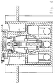
- a housing 1 with the switch is accommodated in a receiving chamber 2 of a mounting frame 3 with a support ring 4. Latches 47 serve for locking.
- the housing 1 has side walls 5 in which the functional parts of the switch are mounted and / or guided. The parts of the switch are mounted in the housing 1.
- the switch is used as a pre-assembled unit in the receiving chamber 2.
- the essential functional parts of the switch are a slide 6 with contacts 7, which face fixed contacts 8.
- the slide 6 is coupled to an arm 9 of a pivot lever 10.
- a second lever 11 of a toggle lever engages in the pivot lever 10, the first lever 12 of which is fixed to the housing.
- the knee joint 13 connecting the two levers 11 and 12 is coupled to the rocker 14, which in turn is mounted fixed to the housing.
- a yoke lever 15 is provided as a release lever, which carries the armature 16 of an electromagnet 17 which acts as a latching piece.
- the housing 1 accommodates the electromagnet 17 in guides 18.
- the electromagnet 17 is immovable and tilt-free in the guides of the housing 1.
- the yoke lever 15 is supported on one side with pins 19 in the side walls 5.
- the armature 16 sits at the other end of the yoke lever 15.
- the yoke lever 15 carries a profile projection 20 with a circular porofoil section 22 which is oriented essentially concentrically to the axis 21 of the first lever 12 of the toggle lever and a subsequent cam section 23.
- the yoke lever 15 takes on an attachment 24
- Helical compression spring 26 which on the other hand is supported on a receptacle 25 of the slide 6. This helical compression spring 26 causes both the triggering and the contact separation or switching off. In the tripped state, the yoke lever 15 engages against a stop 46 of the pivoting lever 10.
- the slide 6 carries three contacts 7 for a three-pole circuit. Details of the contacts are not shown.
- the arm 9 of the pivot lever 10 engages in a window 27 of the slide 6.
- the window 27 and the arm 9 can each be provided in pairs.
- the pivot lever 10 has an opening 28 with a locking lug 29 with which a locking lug 30 of the second lever 11 of the toggle lever acting as a locking lever interacts.
- the second lever 11 also has a shoulder 31 with which the yoke lever 15 cooperates during the triggering process, which will be explained in more detail.
- the profile shoulder 32 interacts with the profile shoulder 20 of the yoke lever 15.
- a circuit board 35 receives electrical components and a converter 36 for current measurement, in particular fault current measurement.
- Two contacts 37 are arranged on the printed circuit board, with which a U-shaped contact bridge 38 interacts.
- the legs 40 of the contact bridge 38 are guided in circular arc guides 41 in the end part of the pivot lever 10 so as to be displaceable in the pivoting direction thereof and are prestressed by a spring 39. Noses 43 of the legs come into contact with stops 42 of the circular arc guides 41.
- the side walls 5 engage with hooks 44 in slots 45 of the circuit board 35. This achieves a stabilization of the arrangement.
- the parts of the switch can be arranged in the housing 1 by inserting, inserting and pressing them in. It is secured and held by stops and catches.
- the housing 1 with the circuit board 35 is inserted into the receiving chamber 2 of the mounting frame 3 and fixed by the locking lugs 47.
- the switch is ready for installation or ready for connection. It can be inserted in an installation box or device housing.
- the yoke lever 15 is held in the position shown by the circular profile sections 22 and 33, where the armature 16 is located at a short distance from the pole faces of the electromagnet 17.
- the locking lug 30 of the lever 11 lies against the locking lug 29.
- the rocker 14 is in the off position.
- the contact bridge 38 is raised from the contacts 37 because the lugs 43 abut the stops 42. As a result, the circuit board 35 is turned off.
- the rocker 14 When switching on, the rocker 14 is pivoted in the counterclockwise direction with reference to FIGS. 1 and 2. The knee joint is stretched. The pivot lever 10 is pivoted clockwise. After a very short swivel path, the contact bridge 38 comes into engagement with the contacts 37, so that a circuit for exciting the circuits on the printed circuit board 35 is closed. The circuits are ready for operation.
- the switch-on time is in any case less than the switching time of the rocker, so that the standby state is safely reached. With the further switch-on movement on the one hand raised by the arms 9 of the slide 6, so that the contacts 7 and 8 close and the spring 26 is tensioned. On the other hand, the yoke lever 15 is held down under the action of the circular profile sections 22 and 33.
- the electromagnet receives power through the electronic circuit.
- the cams 23 and 34 press the yoke lever 15 against the electromagnet 17, so that the armature 16 is securely tightened and the yoke lever 15 is latched.
- the switch is latched in the switched-on state by the electromagnet 17.
- the electronic circuit continuously monitors the current, especially the fault current.
- a trigger signal is issued.
- the electromagnet 17 is de-energized.
- the yoke lever 15 is raised under the action of the spring 26 or pivoted in the counterclockwise direction, so that the yoke lever 15 abuts the shoulder 31 and lifts the lever 11.
- the stop 467 limits the movement of the yoke lever 15.
- the locking lug 30 is lifted out of the locking lug 29.
- the spring 26 pushes the slide 6 downward and thereby separates the contacts.
- the pivot lever 10 is carried in the counterclockwise direction.
- the contact bridge 38 is lifted from the contacts 37, so that the electronic circuit is de-energized.
- Fig. 7 shows an embodiment with a lever-like latching piece 50 which is pivotable about an axis 54.
- a latching nose 55 interacts with a nose 56 of the yoke lever 15. So this switch has a mechanical latch.
- the release of the latching piece 50 can take place thermally by means of a bimetal release 51, that is to say by overcurrent.
- a megantic quick release 52 or an undervoltage release 53 can be provided. Otherwise, the switching function corresponds to the embodiment described above.
Landscapes
- Physics & Mathematics (AREA)
- Electromagnetism (AREA)
- Breakers (AREA)
- Lifting Devices For Agricultural Implements (AREA)
Applications Claiming Priority (2)
| Application Number | Priority Date | Filing Date | Title |
|---|---|---|---|
| DE4233918A DE4233918B4 (de) | 1992-10-08 | 1992-10-08 | Elektrischer Schalter mit Stromüberwachung |
| DE4233918 | 1992-10-08 |
Publications (2)
| Publication Number | Publication Date |
|---|---|
| EP0591679A1 true EP0591679A1 (fr) | 1994-04-13 |
| EP0591679B1 EP0591679B1 (fr) | 1996-12-11 |
Family
ID=6469978
Family Applications (1)
| Application Number | Title | Priority Date | Filing Date |
|---|---|---|---|
| EP93114004A Expired - Lifetime EP0591679B1 (fr) | 1992-10-08 | 1993-09-02 | Commutateur électrique avec contrÔle de courant |
Country Status (5)
| Country | Link |
|---|---|
| US (1) | US5369385A (fr) |
| EP (1) | EP0591679B1 (fr) |
| AU (1) | AU4735793A (fr) |
| DE (2) | DE4233918B4 (fr) |
| ES (1) | ES2095538T3 (fr) |
Cited By (1)
| Publication number | Priority date | Publication date | Assignee | Title |
|---|---|---|---|---|
| EP1168390A1 (fr) * | 2000-06-30 | 2002-01-02 | SIGNAL LUX ITALIA S.p.A. | Interrupteur électrique auto-ouvrant |
Families Citing this family (9)
| Publication number | Priority date | Publication date | Assignee | Title |
|---|---|---|---|---|
| US7180702B2 (en) * | 2004-03-09 | 2007-02-20 | Tandberg Data Cop. | Data cartridges handler including a ring-shaped carousel and a picker within the inner periphery of the carousel |
| US20080282281A1 (en) * | 2007-05-11 | 2008-11-13 | White Christopher M | Cartridge engagement apparatus and method for cartridge library |
| US20080278847A1 (en) * | 2007-05-11 | 2008-11-13 | Barkley John A | Method and apparatus for positioning drives in cartridge library |
| US7777986B2 (en) * | 2007-05-11 | 2010-08-17 | Tandberg Data Corporation | Multi-dimensional transport method and drive subsystems in a cartridge library apparatus |
| US20080282275A1 (en) * | 2007-05-11 | 2008-11-13 | Zaczek Thomas E | Entry/exit port method and apparatus for cartridge library |
| US7777985B2 (en) * | 2007-05-11 | 2010-08-17 | Tandberg Data Corporation | Transport method and apparatus for cartridge library utilizing cam slot and follower for moving a robot carriage |
| KR101869724B1 (ko) * | 2017-01-05 | 2018-06-21 | 엘에스산전 주식회사 | 회로차단기의 전자 트립 장치 |
| KR102299858B1 (ko) * | 2017-03-15 | 2021-09-08 | 엘에스일렉트릭 (주) | 회로차단기의 전자 트립 장치 |
| US10468219B2 (en) * | 2017-09-07 | 2019-11-05 | Carling Technologies, Inc. | Circuit interrupter with status indication |
Citations (3)
| Publication number | Priority date | Publication date | Assignee | Title |
|---|---|---|---|---|
| DE1438953B2 (de) * | 1964-04-11 | 1971-11-25 | Bassani S.P.A., Mailand (Italien) | Selbstschalter |
| DE2132738B1 (de) * | 1971-07-01 | 1972-07-06 | Ellenberger & Poensgen | Ein- oder mehrpoliger UEberstromschalter mit thermischer und/oder elektromagnetischer Ausloesung |
| US4660009A (en) * | 1985-07-29 | 1987-04-21 | Westinghouse Electric Corp. | Modular integral circuit interrupter |
Family Cites Families (13)
| Publication number | Priority date | Publication date | Assignee | Title |
|---|---|---|---|---|
| DE1055102B (de) * | 1956-06-21 | 1959-04-16 | Wickmann Werke Ag | UEberstromschalter |
| DE7201067U (de) * | 1972-01-13 | 1972-04-06 | Bbc Ag | Selbstschalter |
| GB1374768A (en) * | 1972-04-24 | 1974-11-20 | Dorman Smith Switchgear Ltd | Electrical circuit breakers |
| DE2626003A1 (de) * | 1976-06-10 | 1977-12-22 | Schulte Elektrotech | Mehrpoliger druckschalter mit ueberstromausloesung und unterspannungs- bzw. phasenausfallschutz |
| SU1089668A1 (ru) * | 1982-03-12 | 1984-04-30 | Всесоюзный Научно-Исследовательский,Проектно-Конструкторский И Технологический Институт Низковольтного Аппаратостроения "Внииэлектроаппарат" | Расцепитель минимального напр жени автоматического выключател |
| DE3211246C1 (de) * | 1982-03-26 | 1983-07-21 | Ellenberger & Poensgen Gmbh, 8503 Altdorf | UEberstromschutzschalter |
| DE3341874C1 (de) * | 1983-09-08 | 1984-07-19 | Schulte-Elektrotechnik GmbH & Co KG, 5880 Lüdenscheid | Schalteranordnung mit Nullspannungsauslösung |
| SU1325601A1 (ru) * | 1985-09-23 | 1987-07-23 | Ленинградское Электромашиностроительное Объединение "Электросила" Им.С.М.Кирова | Расцепитель минимального напр жени |
| US4623861A (en) * | 1985-10-01 | 1986-11-18 | Carlingswitch, Inc. | Rocker actuator bracket assembly for a split case circuit breaker |
| DE8611082U1 (de) * | 1986-04-23 | 1986-07-17 | Lindner Gmbh, Fabrik Elektrischer Lampen Und Apparate, 8600 Bamberg | Handbetätigter elektrischer Schalter |
| DE3936610C2 (de) * | 1989-11-03 | 2001-11-22 | Schupa Gmbh | Einrichtung zum sprunghaften Einschalten beweglich gelagerter Kontakthebel, insbesondere für einen zweipoligen Fehlerstromschutzschalter |
| DE9004883U1 (de) * | 1990-04-30 | 1990-06-28 | Felten & Guilleaume Energietechnik AG, 5000 Köln | Schaltmechanismus für Niederspannungsschaltgeräte |
| DE9103979U1 (de) * | 1991-04-02 | 1991-06-27 | Felten & Guilleaume Energietechnik AG, 5000 Köln | Schaltmechanismus für Niederspannungsschaltgeräte |
-
1992
- 1992-10-08 DE DE4233918A patent/DE4233918B4/de not_active Expired - Fee Related
-
1993
- 1993-09-02 ES ES93114004T patent/ES2095538T3/es not_active Expired - Lifetime
- 1993-09-02 EP EP93114004A patent/EP0591679B1/fr not_active Expired - Lifetime
- 1993-09-02 DE DE59304740T patent/DE59304740D1/de not_active Expired - Fee Related
- 1993-09-14 AU AU47357/93A patent/AU4735793A/en not_active Abandoned
- 1993-09-21 US US08/124,721 patent/US5369385A/en not_active Expired - Fee Related
Patent Citations (3)
| Publication number | Priority date | Publication date | Assignee | Title |
|---|---|---|---|---|
| DE1438953B2 (de) * | 1964-04-11 | 1971-11-25 | Bassani S.P.A., Mailand (Italien) | Selbstschalter |
| DE2132738B1 (de) * | 1971-07-01 | 1972-07-06 | Ellenberger & Poensgen | Ein- oder mehrpoliger UEberstromschalter mit thermischer und/oder elektromagnetischer Ausloesung |
| US4660009A (en) * | 1985-07-29 | 1987-04-21 | Westinghouse Electric Corp. | Modular integral circuit interrupter |
Cited By (1)
| Publication number | Priority date | Publication date | Assignee | Title |
|---|---|---|---|---|
| EP1168390A1 (fr) * | 2000-06-30 | 2002-01-02 | SIGNAL LUX ITALIA S.p.A. | Interrupteur électrique auto-ouvrant |
Also Published As
| Publication number | Publication date |
|---|---|
| US5369385A (en) | 1994-11-29 |
| AU4735793A (en) | 1994-04-21 |
| DE59304740D1 (de) | 1997-01-23 |
| DE4233918B4 (de) | 2004-02-26 |
| ES2095538T3 (es) | 1997-02-16 |
| DE4233918A1 (de) | 1994-04-14 |
| EP0591679B1 (fr) | 1996-12-11 |
Similar Documents
| Publication | Publication Date | Title |
|---|---|---|
| DE68912738T2 (de) | Modulschützschalter mit Hilfsauslöseblock mit einer automatischen oder unabhängigen Wiedereinschaltung. | |
| DE69419670T2 (de) | Betätigungsmechanismus für elektrischen Modulschutzschalter | |
| DE69312154T2 (de) | Mechanische Verriegelungsvorrichtung von zwei Schaltern mit Isolierstoff-Formgehäuse | |
| EP0317660B1 (fr) | Contacteur | |
| SK278330B6 (en) | Protection equipment of switching apparatus | |
| DE2809754C2 (de) | Zweipoliger Schutzschalter | |
| DE3719899A1 (de) | Mit hilfsmodul kombinierte ausloeseeinheit fuer elektronische schalter | |
| DE670790C (de) | Thermisch wirkender Selbstschalter | |
| EP0591679B1 (fr) | Commutateur électrique avec contrÔle de courant | |
| DE19631533A1 (de) | Lastschaltanlagen zur hochspannungsseitigen Abschaltung von Verteiltransformatoren | |
| DE69505201T2 (de) | Leistungsschalter | |
| DE68920538T2 (de) | Ferngesteuerter Schutzschalter. | |
| EP1884976B1 (fr) | Dispositif de commutation doté d'un élément d'actionnement | |
| DE2118175A1 (de) | Leistungsschalter mit eingebauten Schmelzsicherungen | |
| DE3341874C1 (de) | Schalteranordnung mit Nullspannungsauslösung | |
| DE1463122B2 (de) | Druckknopfbetätigter Überstromschalter mit Handausschaltung | |
| DE1229631B (de) | Schalteranordnung mit einem Selbstschalter und Schmelzsicherungen | |
| DE10158255A1 (de) | Leitungsschutzschalter mit Sofortauslösung | |
| DE69422134T2 (de) | Elektrischer Schutzvorrichtung mit Lastschalter und Effektor | |
| EP0556602B1 (fr) | Déclencheur thermique pour appareils de commutation électriques | |
| EP0802552A2 (fr) | Interrupteur électrique à déclenchement par manque de tension | |
| EP0849759B1 (fr) | Appareil de coupure pour une installation électrique | |
| DE69309120T2 (de) | Kombinierter Schutzschalter und Nulleiterschalter mit einer Isolationskappe | |
| DE19735408A1 (de) | Schaltmechanismus für einen Schutzschalter | |
| DE698284C (de) | Thermisch wirkender Selbstschalter |
Legal Events
| Date | Code | Title | Description |
|---|---|---|---|
| PUAI | Public reference made under article 153(3) epc to a published international application that has entered the european phase |
Free format text: ORIGINAL CODE: 0009012 |
|
| AK | Designated contracting states |
Kind code of ref document: A1 Designated state(s): CH DE ES FR GB IT LI PT |
|
| 17P | Request for examination filed |
Effective date: 19941006 |
|
| GRAG | Despatch of communication of intention to grant |
Free format text: ORIGINAL CODE: EPIDOS AGRA |
|
| GRAH | Despatch of communication of intention to grant a patent |
Free format text: ORIGINAL CODE: EPIDOS IGRA |
|
| 17Q | First examination report despatched |
Effective date: 19960529 |
|
| GRAH | Despatch of communication of intention to grant a patent |
Free format text: ORIGINAL CODE: EPIDOS IGRA |
|
| GRAA | (expected) grant |
Free format text: ORIGINAL CODE: 0009210 |
|
| AK | Designated contracting states |
Kind code of ref document: B1 Designated state(s): CH DE ES FR GB IT LI PT |
|
| ITF | It: translation for a ep patent filed | ||
| REF | Corresponds to: |
Ref document number: 59304740 Country of ref document: DE Date of ref document: 19970123 |
|
| REG | Reference to a national code |
Ref country code: ES Ref legal event code: FG2A Ref document number: 2095538 Country of ref document: ES Kind code of ref document: T3 |
|
| GBT | Gb: translation of ep patent filed (gb section 77(6)(a)/1977) |
Effective date: 19970125 |
|
| RAP2 | Party data changed (patent owner data changed or rights of a patent transferred) |
Owner name: MODELEC S.A. |
|
| ET | Fr: translation filed | ||
| PG25 | Lapsed in a contracting state [announced via postgrant information from national office to epo] |
Ref country code: PT Effective date: 19970311 |
|
| PLBE | No opposition filed within time limit |
Free format text: ORIGINAL CODE: 0009261 |
|
| 26N | No opposition filed | ||
| REG | Reference to a national code |
Ref country code: GB Ref legal event code: IF02 |
|
| PGFP | Annual fee paid to national office [announced via postgrant information from national office to epo] |
Ref country code: FR Payment date: 20030922 Year of fee payment: 11 |
|
| PGFP | Annual fee paid to national office [announced via postgrant information from national office to epo] |
Ref country code: ES Payment date: 20030924 Year of fee payment: 11 |
|
| PG25 | Lapsed in a contracting state [announced via postgrant information from national office to epo] |
Ref country code: ES Free format text: LAPSE BECAUSE OF NON-PAYMENT OF DUE FEES Effective date: 20040903 |
|
| PG25 | Lapsed in a contracting state [announced via postgrant information from national office to epo] |
Ref country code: FR Free format text: LAPSE BECAUSE OF NON-PAYMENT OF DUE FEES Effective date: 20050531 |
|
| REG | Reference to a national code |
Ref country code: FR Ref legal event code: ST |
|
| PG25 | Lapsed in a contracting state [announced via postgrant information from national office to epo] |
Ref country code: IT Free format text: LAPSE BECAUSE OF NON-PAYMENT OF DUE FEES Effective date: 20050902 |
|
| REG | Reference to a national code |
Ref country code: ES Ref legal event code: FD2A Effective date: 20040903 |
|
| PGFP | Annual fee paid to national office [announced via postgrant information from national office to epo] |
Ref country code: DE Payment date: 20070810 Year of fee payment: 15 |
|
| PGFP | Annual fee paid to national office [announced via postgrant information from national office to epo] |
Ref country code: CH Payment date: 20070803 Year of fee payment: 15 |
|
| PGFP | Annual fee paid to national office [announced via postgrant information from national office to epo] |
Ref country code: GB Payment date: 20070921 Year of fee payment: 15 |
|
| REG | Reference to a national code |
Ref country code: CH Ref legal event code: PL |
|
| GBPC | Gb: european patent ceased through non-payment of renewal fee |
Effective date: 20080902 |
|
| PG25 | Lapsed in a contracting state [announced via postgrant information from national office to epo] |
Ref country code: DE Free format text: LAPSE BECAUSE OF NON-PAYMENT OF DUE FEES Effective date: 20090401 |
|
| PG25 | Lapsed in a contracting state [announced via postgrant information from national office to epo] |
Ref country code: LI Free format text: LAPSE BECAUSE OF NON-PAYMENT OF DUE FEES Effective date: 20080930 Ref country code: CH Free format text: LAPSE BECAUSE OF NON-PAYMENT OF DUE FEES Effective date: 20080930 |
|
| PG25 | Lapsed in a contracting state [announced via postgrant information from national office to epo] |
Ref country code: GB Free format text: LAPSE BECAUSE OF NON-PAYMENT OF DUE FEES Effective date: 20080902 |