EP0591686A2 - Connecting element for ignition device - Google Patents
Connecting element for ignition device Download PDFInfo
- Publication number
- EP0591686A2 EP0591686A2 EP93114204A EP93114204A EP0591686A2 EP 0591686 A2 EP0591686 A2 EP 0591686A2 EP 93114204 A EP93114204 A EP 93114204A EP 93114204 A EP93114204 A EP 93114204A EP 0591686 A2 EP0591686 A2 EP 0591686A2
- Authority
- EP
- European Patent Office
- Prior art keywords
- voltage
- connecting part
- ignition coil
- spark plug
- switching element
- Prior art date
- Legal status (The legal status is an assumption and is not a legal conclusion. Google has not performed a legal analysis and makes no representation as to the accuracy of the status listed.)
- Granted
Links
Images

Classifications
-
- H—ELECTRICITY
- H01—ELECTRIC ELEMENTS
- H01T—SPARK GAPS; OVERVOLTAGE ARRESTERS USING SPARK GAPS; SPARKING PLUGS; CORONA DEVICES; GENERATING IONS TO BE INTRODUCED INTO NON-ENCLOSED GASES
- H01T13/00—Sparking plugs
- H01T13/02—Details
- H01T13/04—Means providing electrical connection to sparking plugs
Definitions
- the invention relates to a connecting part of an ignition system for internal combustion engines according to the preamble of claim 1.
- the connecting part which is formed by its use as a spark plug connector, has a high-voltage switching element in the form of a breakover diode with which the voltage supplied to the spark plug is controlled.
- This high-voltage switching element which suddenly changes from an electrically blocking to an electrically conductive state when the breakover voltage is supplied by the ignition coil of the ignition system and acts on the downstream spark plug with a voltage jump, enables the influences of shunts on the spark plug, which cause the formation of the ignition sparks on the Electrodes of the spark plug make it difficult to largely eliminate them.
- the prerequisite for this is that the voltage jump triggered by the high-voltage switching element reaches the ignition voltage required to form ignition sparks at the candle electrodes.
- the voltage jump is a partial voltage of the breakover voltage, which depends on the component and the design of the high-voltage switching element.
- the breakover voltage in turn is smaller than the output voltage of the ignition coil by a loss voltage.
- the loss voltage that results from the capacity distribution in the ignition system is greater with respect to the location of the high-voltage switching element, the greater the sum of the upstream and the downstream capacitance , compared to the upstream capacity.
- the high-voltage switching element In order to compensate for this loss voltage, in order to achieve a predetermined minimum ignition voltage, the high-voltage switching element must be designed for a correspondingly higher breakover voltage than the ignition voltage. As a result, the ignition coil must also provide a very high output voltage. However, high voltages pose a reliability risk because undesirable capacitive arc discharges with electrode erosion can occur on the spark plug. In addition, the high-voltage switching element and the ignition coil must be correspondingly high-voltage resistant, which leads to a high price of these components.
- the arrangement of the insulating material housing of the connecting part is assigned an arrangement which increases the capacitance of the area between the high-voltage switching element and the connecting element and the use of a high-voltage switching element with a low breakover voltage and, as a result, also the use of an ignition coil with a low output voltage, which reduces the manufacturing costs of the ignition system.
- the arrangement described is the connecting part of an ignition system for a multi-cylinder internal combustion engine, which, through its use, serves as a spark plug connector and in which a separate ignition unit with an ignition coil and an integrated spark plug connector is used for each cylinder.
- the single figure shows in cross section a section of a cylinder head 11 of an internal combustion engine with an ignition unit 12, not shown in more detail, the ignition coil 13 of which is only indicated and the one spark plug connector 14 with a spark plug 17 fastened in a plug shaft 16 of the cylinder head 11 connected is.
- the spark plug connector 14 with a longitudinal axis 18 has a cylindrical structure in the basic form with an outer sleeve 19 made of silicone rubber, an injection molded thermosetting, outer cylindrical cylindrical insulating material housing 20, into which a pin-shaped connecting element 21 and an electrically connected in series Switched, with a cylindrical outer shape provided high-voltage switching element 22, which is designed as a breakover diode, are directly embedded.
- the spark plug 17 is screwed in the usual way into a threaded bore 27 of the cylinder head 11 and it carries at the end, opposite the connecting pin 26, a ground electrode 28 and a center electrode 29, between which, when an ignition voltage is applied there is a sparkover at the center electrode 29.
- a distribution of capacity with a pre-capacity consisting of the capacity of the ignition coil 13 and the adjoining part of the spark plug connector 14 in front of the installation location, results along the arrangement described in the direction of the energy flow from the ignition coil 13 to the spark plug 17
- High-voltage switching element 22 with respect to earth potential and a post-capacitance with respect to earth potential consisting of the capacitance of the part of the spark plug connector 14 between the high-voltage switching element 22 and the spark plug 17, and the capacitance of the spark plug 17.
- a hollow cylindrical metal cup 32 is attached to the spark plug connector 14 between the connecting element 23 and the connecting part 24 on an outer side 31 of the insulating material housing 20 and a metallic, hollow cylindrical shield 34 is attached to an outer jacket 33 of the casing 19.
- the metal cup 32 is electrically connected to the high-voltage connection via the connection element 23 Ignition coil 13 connected and the metallic screen 34, via externally attached to the screen 34 resilient tabs 36 in frictional engagement and in electrical connection with the ground potential cylinder head 11.
- the screen 34 can also have a screen voltage, the amount of which between that of the output voltage the ignition coil 13 and the earth potential and the screen 34 can be fastened together with the ignition coil 13 via fastening elements to the cylinder head 11 which is at earth potential.
- a capacitance is thus formed between the metal cup 32 and the screen 34, with a part of the casing 19 as a dielectric. This capacitance is greater, the greater the amount of shield voltage and the smaller the thickness of the dielectric, which is not more than 3 mm.
- the output voltage of the ignition coil 13 is present at the connection element 23 of the spark plug connector 14 which is connected to the high-voltage connection of the ignition coil 13.
- the connecting element 23 is connected to the high-voltage switching element 22 via the connecting element 21.
- a voltage hereinafter referred to as a voltage jump
- the voltage jump arrives at the connection part 24 for receiving the connection pin 26 of the spark plug 17.
- the ignition voltage ultimately occurring leads, in a known manner, to spark ignition of a fuel-air mixture in an associated cylinder of the internal combustion engine by sparkover between the center electrode 29 and the ground electrode 28.
- the voltage jump is a partial voltage of the breakover voltage, which depends on the component and the design of the high-voltage switching element 22.
- the breakover voltage in turn is smaller than the output voltage of the ignition coil by a loss voltage.
- the loss voltage can be changed by the capacitance distribution in the spark plug connector 14. It is the greater, the larger, based on the location of the high-voltage switching element 22 and in the direction of the energy flow from the ignition coil 13 to the spark plug 17, the sum of the pre-and after-capacity compared to the pre-capacity.
- This loss voltage is reduced by a separate increase in the pre-capacitance, which is realized by the capacitance which is formed between the metal cup 32 and the screen 34 and which lies in front of the high-voltage switching element 22 in the direction of the energy flow.
Landscapes
- Ignition Installations For Internal Combustion Engines (AREA)
- Spark Plugs (AREA)
Abstract
Es ist für eine Brennkraftmaschine, bei der für jeden Zylinder eine eigene Zündeinheit (12) mit einer Zündspule (13) und einem Zündkerzenstecker (14) verwendet wird, der Zündkerzenstecker (14) hinsichtlich seiner Kapazität so auszuführen, daß der Spannungsverlust zwischen der Zündspule (13) und einem im Zündkerzenstecker (14) angeordneten Hochspannungsschaltelement (22) möglichst gering ist.For an internal combustion engine in which a separate ignition unit (12) with an ignition coil (13) and a spark plug connector (14) is used for each cylinder, the capacity of the spark plug connector (14) is such that the voltage loss between the ignition coil ( 13) and a high-voltage switching element (22) arranged in the spark plug connector (14) is as small as possible.
Dazu ist der Zündkerzenstecker (14) so ausgestaltet, daß durch einen, an der Ausgangsspannung der Zündspule (13) angeschlossenen Metallbecher (32), der einem, auf Erdpotential liegenden metallischen Schirm (34) koaxial gegenübersteht, neben den bauteilbedingten Kapazitäten der Zündanlage, eine Zusatzkapazität gebildet ist. Diese ist im Zündkerzenstecker (14) so angeordnet, daß sie zwischen dessen Anschlußelement (23) für den Hochspannungsanschluß der Zündspule (13) und dem elektrischen Schalter (22) liegt. Durch diese Anordnung der Zusatzkapazität in dem Zündkerzenstecker (14) wird die Verlustspannung zwischen der Zündspule (13) und dem Hochspannungsschaltelement (22) abgesenkt.For this purpose, the spark plug connector (14) is designed in such a way that, in addition to the component-related capacities of the ignition system, a metal cup (32) connected to the output voltage of the ignition coil (13) and coaxially opposite a metal shield (34) which is at ground potential Additional capacity is formed. This is arranged in the spark plug connector (14) so that it lies between the connecting element (23) for the high-voltage connection of the ignition coil (13) and the electrical switch (22). This arrangement of the additional capacity in the spark plug connector (14) lowers the loss voltage between the ignition coil (13) and the high-voltage switching element (22).
Diese Anordnung wird im Automobilbau, insbesondere bei Brennkraftmaschinen, eingesetzt.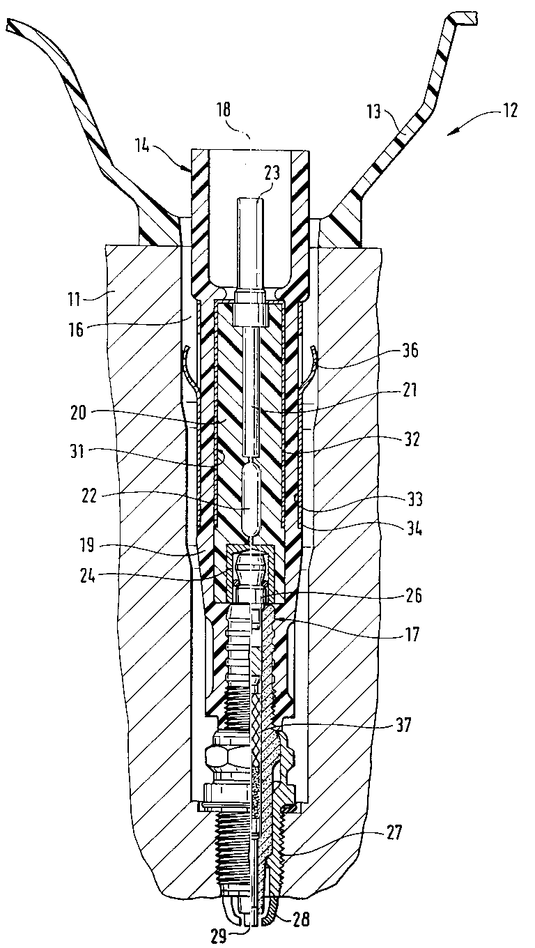
Description
Die Erfindung betrifft ein Verbindungsteil einer Zündanlage für Brennkraftmaschinen entsprechend der Gattung des Patentanspruchs 1. Das Verbindungsteil, das durch seine Verwendung als Zündkerzenstecker ausgebildet ist, weist ein Hochspannungsschaltelement in Form einer Kippdiode auf, mit dem die der Zündkerze zugeleitete Spannung gesteuert wird. Dieses Hochspannungsschaltelement, das bei einer von der Zündspule der Zündanlage zugeführten Kippspannung sprungartig vom elektrisch sperrenden in einen elektrisch leitenden Zustand übergeht und die nachgeordnete Zündkerze mit einen Spannungssprung beaufschlagt, ermöglicht es, die Einflüsse von Nebenschlüssen an der Zündkerze, die die Bildung der Zündfunken an den Elektroden der Zündkerze erschweren, weitgehend zu eleminieren.The invention relates to a connecting part of an ignition system for internal combustion engines according to the preamble of claim 1. The connecting part, which is formed by its use as a spark plug connector, has a high-voltage switching element in the form of a breakover diode with which the voltage supplied to the spark plug is controlled. This high-voltage switching element, which suddenly changes from an electrically blocking to an electrically conductive state when the breakover voltage is supplied by the ignition coil of the ignition system and acts on the downstream spark plug with a voltage jump, enables the influences of shunts on the spark plug, which cause the formation of the ignition sparks on the Electrodes of the spark plug make it difficult to largely eliminate them.
Voraussetzung dafür ist, daß der durch das Hochspannungsschaltelement ausgelöste Spannungssprung die zur Bildung von Zündfunken erforderliche Zündspannung an den Kerzenelektroden erreicht. Der Spannungssprung ist eine Teilspannung der Kippspannung, die bauteilspezifisch von der Ausgestaltung des Hochspannungsschaltelements abhängt. Die Kippspannung wiederum ist um eine Verlustspannung kleiner als die Ausgangsspannung der Zündspule.The prerequisite for this is that the voltage jump triggered by the high-voltage switching element reaches the ignition voltage required to form ignition sparks at the candle electrodes. The voltage jump is a partial voltage of the breakover voltage, which depends on the component and the design of the high-voltage switching element. The breakover voltage in turn is smaller than the output voltage of the ignition coil by a loss voltage.
Betrachtet man die Zündanlage entsprechend dem Energiefluß von der Zündspule ausgehend zur Zündkerze hin, so ist die Verlustspannung, die sich aufgrund der Kapazitätsverteilung in der Zündanlage ergibt, bezogen auf den Ort des Hochspannungsschaltelements um so größer, je größer die Summe der vorgelagerten mit der nachgelagerten Kapazität, gegenüber der vorgelagerten Kapazität ist.If one considers the ignition system according to the energy flow from the ignition coil to the spark plug, the loss voltage that results from the capacity distribution in the ignition system is greater with respect to the location of the high-voltage switching element, the greater the sum of the upstream and the downstream capacitance , compared to the upstream capacity.
Um diese Verlustspannung auszugleichen, muß, um eine vorgegebene Mindestzündspannung zu erreichen, das Hochspannungsschaltelement auf eine entsprechend höhere Kippspannung als die Zündspannung ausgelegt sein. Infolgedessen muß auch die Zündspule eine sehr hohe Ausgangsspannung bereitstellen. Hohe Spannung bilden aber ein Zuverlässigkeitsrisiko, weil unerwünschterweise kapazitive Bogenentladungen mit Elektrodenerosion an der Zündkerze auftreten können. Zudem müssen das Hochspannungschaltelement und die Zündspule entsprechend hochspannungsfest sein, was zu einem hohen Preis dieser Bauteile führt.In order to compensate for this loss voltage, in order to achieve a predetermined minimum ignition voltage, the high-voltage switching element must be designed for a correspondingly higher breakover voltage than the ignition voltage. As a result, the ignition coil must also provide a very high output voltage. However, high voltages pose a reliability risk because undesirable capacitive arc discharges with electrode erosion can occur on the spark plug. In addition, the high-voltage switching element and the ignition coil must be correspondingly high-voltage resistant, which leads to a high price of these components.
Bei der erfindungsgemäßen Anordnung mit den kennzeichnenden Merkmalen des Anspruchs 1 wird der im Stand der Technik dargelegte Nachteil vermieden und mit einfachen Maßnahmen eine Zündanlage verwirklicht, die auf niedrigerem Spannungsniveau arbeitet.In the arrangement according to the invention with the characterizing features of claim 1, the disadvantage set out in the prior art is avoided and an ignition system which operates at a lower voltage level is implemented with simple measures.
Dazu ist dem Isolierstoffgehäuse des Verbindungsteils eine die Kapazität des Bereichs zwischen Hochspannungsschaltelement und Anschlußelement erhöhende Anordnung zugeordnet und die Verwendung eines Hochspannungsschaltelements mit niedriger Kippspannung und als Folge davon auch die Verwendung einer Zündspule mit geringer Ausgangsspannung ermöglicht was die Herstellkosten der Zünndanlage ermäßigt.For this purpose, the arrangement of the insulating material housing of the connecting part is assigned an arrangement which increases the capacitance of the area between the high-voltage switching element and the connecting element and the use of a high-voltage switching element with a low breakover voltage and, as a result, also the use of an ignition coil with a low output voltage, which reduces the manufacturing costs of the ignition system.
Vorteilhafte Weiterbildungen der Erfindung sind in den Unteransprüchen beschrieben.Advantageous developments of the invention are described in the subclaims.
Ein Ausführungsbeispiel der Erfindung ist in der Zeichnung dargestellt und in der Figurenbeschreibung näher erläutert. Es zeigt die einzige Figur in einer Schnittdarstellung die Zündanlage ausschnittsweise in vereinfachter Form.An embodiment of the invention is shown in the drawing and explained in more detail in the description of the figures. The single figure shows a section of the ignition system in a simplified form.
Bei der beschriebenen Anordnung handelt es sich um das Verbindungsteil einer Zündanlage für eine Mehrzylinder-Brennkraftmaschine, das durch seine Verwendung als Zündkerzenstecker dient und bei der für jeden Zylinder eine eigene Zündeinheit mit einer Zündspule und einem darin integrierten Zündkerzenstecker verwendet wird.The arrangement described is the connecting part of an ignition system for a multi-cylinder internal combustion engine, which, through its use, serves as a spark plug connector and in which a separate ignition unit with an ignition coil and an integrated spark plug connector is used for each cylinder.
Die einzige Figur zeigt im Querschnitt ausschnittsweise einen Zylinderkopf 11 einer Brennkraftmaschine mit einer, in nicht näher dargestellter Weise daran befestigten Zündeinheit 12, deren eine Zündspule 13 nur angedeutet ist und deren einer Zündkerzenstecker 14 mit einer, in einem Kerzenschacht 16 des Zylinderkopfes 11 befestigten Zündkerze 17 verbunden ist.The single figure shows in cross section a section of a
Der Zündkerzenstecker 14 mit einer Längsachse 18 weist einen in der Grundform zylindrischen Aufbau auf mit einer außenliegenden, aus Silikongummi bestehenden Hülle 19, einem im Spritzgußverfahren hergestellten duroplastischen, in der Außenform zylindrischen Isolierstoffgehäuse 20, in das ein stiftförmiges Verbindungselement 21 und ein damit elektrisch in Reihe geschalteter, mit einer zylindrischen Außenform versehenes Hochspannungsschaltelement 22, das als Kippdiode ausgebildet ist, direkt eingebettet sind.The
An dem freien Ende des Verbindungselements 21 ist ein aus dem Isolierstoffgehäuse 20 heraustretendes Anschlußelement 23 für den nicht mehr dargestellten Hochspannungsanschluß der Zündspule 13 und an dem freien Ende des Hochspannungsschaltelements 22 ein Anschlußteil 24 in dem Isolierstoffgehäuse 20 eingebettet mit an der Stirnseite des Isolierstoffgehäuses 20 angeordneter Öffnung für die Aufnahme eines Anschlußstiftes 26 der Zündkerze 17. Die Zündkerze 17 ist in üblicher Weise in einer Gewindebohrung 27 des Zylinderkopfes 11 eingeschraubt und sie trägt endseitig, dem Anschlußstift 26 entgegengesetzt, eine Masseelektrode 28 und eine Mittelelektrode 29, zwischen denen, bei Anliegen einer Zündspannung an der Mittelelektrode 29, ein Funkenüberschlag stattfindet.At the free end of the connecting
Bezogen auf den Einbauort des Hochspannungsschaltelements 22 ergibt sich entlang der beschriebenen Anordnung in Richtung des Energieflusses von der Zündspule 13 zur Zündkerze 17 eine Kapazitätsverteilung mit einer Vorkapazität, bestehend aus der Kapazität der Zündspule 13 und des sich daran anschließenden Teils des Zündkerzensteckers 14 vor dem Einbauort des Hochspannungsschaltelements 22 gegenüber Erdpotential und einer Nachkapazität gegenüber Erdpotential, bestehend aus der Kapazität des Teils des Zündkerzensteckers 14 zwischen dem Hochspannungsschaltelement 22 und der Zündkerze 17, sowie der Kapazität der Zündkerze 17. Diese beiden Kapazitäten ergeben sich ohne eine zusätzliche Fremdbeschaltung aus der Bauart und der Anbringung am Einbauort der genannten Bauteile, insbesondere aus ihrem Abstand zum auf Erdpotential liegenden Zylinderkopf 11.Based on the installation location of the high-
An dem Zündkerzenstecker 14 ist erfindungsgemäß zwischen dem Anschlußelement 23 und dem Anschlußteil 24 an einer Außenseite 31 des Isolierstoffgehäuses 20 ein hohlzylindrischer Metallbecher 32 und an einem Außenmantel 33 der Hülle 19 ein metallischer, hohlzylindrischer Schirm 34 angebracht. Der Metallbecher 32 ist über das Anschlußelement 23 elektrisch mit dem Hochspannungsanschluß der Zündspule 13 verbunden und der metallische Schirm 34 ist, über außen an dem Schirm 34 angebrachte federnde Laschen 36 in Kraftschluß und in elektrischer Verbindung mit dem auf Erdpotential liegenden Zylinderkopf 11. Prinzipiell kann der Schirm 34 auch eine Schirmspannung aufweisen, deren Betrag zwischen dem der Ausgangsspannung der Zündspule 13 und dem Erdpotential liegt und der Schirm 34 kann zusammen mit der Zündspule 13 über Befestigungselemente am auf Erdpotential liegenden Zylinderkopf 11 elektrisch leitend befestigt sein.According to the invention, a hollow
Somit ist zwischen dem Metallbecher 32 und dem Schirm 34 eine Kapazität gebildet, mit einem Teil der Hülle 19 als Dielektrikum. Diese Kapazität ist umso größer, je größer der Betrag der Schirmspannung und je geringer die Dicke des Dielektrikums, die nicht mehr als 3 mm beträgt, ist.A capacitance is thus formed between the
Die beschriebene Anordnungsdarstellung ergibt den folgenden Funktions- und Wirkungsablauf. Beim Betrieb der Zündanlage liegt an dem mit dem Hochspannungsanschluß der Zündspule 13 verbundenen Anschlußelement 23 des Zündkerzensteckers 14 die Ausgangsspannung der Zündspule 13 an. Das Anschlußelement 23 ist über das Verbindungselement 21 mit dem Hochspannungsschaltelement 22 verbunden. Dieses geht beim Erreichen einer Kippspannung sprungartig von einem elektrisch sperrenden Zustand in einen elektrisch leitenden Zustand reversibel über. An dem, dem Verbindungselement 21 abgewandten Ende des Hochspannungsschaltelements 22 wird beim Umschalten in den leitenden Zustand eine Spannung, im folgenden als Spannungssprung bezeichnet, abgegeben, der geringer als die Kippspannung ist. Der Spannungssprung gelangt auf das Anschlußteil 24 für die Aufnahme des Anschlußstiftes 26 der Zündkerze 17. Diese weist in ihrem Längsverlauf einen Entstörwiderstand 37 und endseitig die Mittelelektrode 29 auf, der, gesteuert durch das Hochspannungsschaltelement 22, gegenüber der auf Erdpotential liegenden benachbarten Masseelektrode 28 im Durchschaltzustand des Hochspannungsschaltelements 22 der Spannungssprung zufließt. Die letztlich auftretende Zündspannung führt in bekannter Weise durch Funkenüberschlag zwischen der Mittelelektrode 29 und der Masseelektrode 28 zu einer Entzündung eines Kraftstoffs-Luft-Gemisches in einem zugehörigen Zylinder der Brennkraftmaschine.The arrangement diagram described results in the following sequence of functions and effects. When the ignition system is operating, the output voltage of the
Der Spannungssprung ist eine Teilspannung der Kippspannung, die bauteilspezifisch von der Ausgestaltung des Hochspannungsschaltelements 22 abhängt. Die Kippspannung wiederum ist um eine Verlustspannung kleiner als die Ausgangsspannung der Zündspule.The voltage jump is a partial voltage of the breakover voltage, which depends on the component and the design of the high-
Die Verlustspannung ist durch die Kapazitätsverteilung in dem Zündkerzenstecker 14 veränderbar. Sie ist umso größer, je größer, bezogen auf den Ort des Hochspannungsschaltelements 22 und in Richtung des Energieflusses von der Zündspule 13 zur Zündkerze 17 betrachtet, die Summe der Vor- und Nachkapazität gegenüber der Vorkapazität ist. Durch eine separate Anhebung der Vorkapazität wird diese Verlustspannung vermindert, was durch die Kapazität, die zwischen Metallbecher 32 und Schirm 34 gebildet wird und die in Richtung des Energieflusses vor dem Hochspannungsschaltelement 22 liegt, verwirklicht wird.The loss voltage can be changed by the capacitance distribution in the
Damit lassen sich Zündanlagen realisieren, die, bei einer vorgegebenen Zündspannung, ein Hochspannungsschaltelement 22 mit niedriger Kippspannung und eine Zündspule 13 mit niedriger Ausgangsspannung aufweisen und die dadurch, bei einem Zugewinn an Betriebssicherheit, kostengünstiger zu fertigen sind.This makes it possible to implement ignition systems which, for a given ignition voltage, have a high-
Claims (10)
Applications Claiming Priority (2)
| Application Number | Priority Date | Filing Date | Title |
|---|---|---|---|
| DE4234077A DE4234077A1 (en) | 1992-10-09 | 1992-10-09 | Connecting part of an ignition system |
| DE4234077 | 1992-10-09 |
Publications (3)
| Publication Number | Publication Date |
|---|---|
| EP0591686A2 true EP0591686A2 (en) | 1994-04-13 |
| EP0591686A3 EP0591686A3 (en) | 1995-02-15 |
| EP0591686B1 EP0591686B1 (en) | 1997-02-05 |
Family
ID=6470083
Family Applications (1)
| Application Number | Title | Priority Date | Filing Date |
|---|---|---|---|
| EP93114204A Expired - Lifetime EP0591686B1 (en) | 1992-10-09 | 1993-09-04 | Connecting element for ignition device |
Country Status (5)
| Country | Link |
|---|---|
| US (1) | US5370100A (en) |
| EP (1) | EP0591686B1 (en) |
| JP (1) | JPH06203943A (en) |
| DE (2) | DE4234077A1 (en) |
| ES (1) | ES2097953T3 (en) |
Families Citing this family (6)
| Publication number | Priority date | Publication date | Assignee | Title |
|---|---|---|---|---|
| US5716223A (en) * | 1996-02-29 | 1998-02-10 | General Motors Corporation | Spark plug boot insulator |
| US6617769B2 (en) * | 2000-06-30 | 2003-09-09 | Ngk Spark Plug Co., Ltd. | Spark plug and mounting structure of the same |
| EP1176681B1 (en) * | 2000-07-28 | 2004-03-17 | Federal-Mogul Ignition Srl | Ignition coil for vehicles |
| WO2006137168A1 (en) * | 2005-06-20 | 2006-12-28 | Hugle Electronics Inc. | Discharge unit for ac ionizer |
| US8316833B2 (en) * | 2009-05-13 | 2012-11-27 | Feng-Kuei Chen | Ignition enhancer for a vehicle engine |
| DE102018108292B4 (en) * | 2017-11-17 | 2023-05-11 | Borgwarner Ludwigsburg Gmbh | Connector for connecting an ignition coil to a spark plug and protective tube for a connector |
Family Cites Families (16)
| Publication number | Priority date | Publication date | Assignee | Title |
|---|---|---|---|---|
| DE143941C (en) * | ||||
| US1554252A (en) * | 1925-09-22 | Poration | ||
| GB927725A (en) * | 1960-09-09 | 1963-06-06 | Lucas Industries Ltd | Electric spark ignition apparatus for prime movers |
| DE1232399B (en) * | 1960-11-09 | 1967-01-12 | Kurt Willutzki Dipl Ing | Ignition transformer for fuel-air mixtures |
| US3535582A (en) * | 1968-03-18 | 1970-10-20 | Joslyn Mfg & Supply Co | Unitary series spark gap with aligned apertures |
| DE1951015C3 (en) * | 1969-10-09 | 1979-02-15 | Siemens Ag, 1000 Berlin Und 8000 Muenchen | Derive method for manufacturing a surge button |
| BE789890A (en) * | 1971-10-12 | 1973-02-01 | Western Electric Co | PROTECTION AGAINST OVERVOLTAGES, WITH A DISCHARGE TUBE, AND ITS EMBODIMENT PROCESS |
| DE2418261B2 (en) * | 1974-04-16 | 1976-05-13 | Siemens AG, 1000 Berlin und 8000 München | SPARK GAP COMPONENT FOR IGNITION SYSTEMS IN COMBUSTION MACHINES |
| US4514712A (en) * | 1975-02-13 | 1985-04-30 | Mcdougal John A | Ignition coil |
| US4082980A (en) * | 1975-02-13 | 1978-04-04 | Murata Manufacturing Co., Ltd. | Spark plug cap providing a capacitor in parallel with the spark cap |
| US4123688A (en) * | 1975-02-13 | 1978-10-31 | Murata Manufacturing Co., Ltd. | Spark plug cap |
| JPS5842620Y2 (en) * | 1979-04-24 | 1983-09-27 | 日産自動車株式会社 | plasma igniter |
| US4277724A (en) * | 1979-10-18 | 1981-07-07 | The Economy Engine Company | Integral spark plug coil for automotive-type plug |
| DE3544870A1 (en) * | 1985-12-18 | 1987-06-19 | Beru Werk Ruprecht Gmbh Co A | SPARK PLUG |
| DE3730118A1 (en) * | 1987-09-08 | 1989-03-16 | Beru Werk Ruprecht Gmbh Co A | Spark plug connector |
| DE3935379A1 (en) * | 1989-10-24 | 1991-04-25 | Bosch Gmbh Robert | HIGH VOLTAGE SWITCHING WITH HIGH VOLTAGE SWITCH MADE OF OPTOELECTRIC SEMICONDUCTOR ELEMENTS |
-
1992
- 1992-10-09 DE DE4234077A patent/DE4234077A1/en not_active Withdrawn
-
1993
- 1993-08-25 US US08/111,713 patent/US5370100A/en not_active Expired - Fee Related
- 1993-09-04 DE DE59305384T patent/DE59305384D1/en not_active Expired - Fee Related
- 1993-09-04 EP EP93114204A patent/EP0591686B1/en not_active Expired - Lifetime
- 1993-09-04 ES ES93114204T patent/ES2097953T3/en not_active Expired - Lifetime
- 1993-10-05 JP JP5249146A patent/JPH06203943A/en active Pending
Also Published As
| Publication number | Publication date |
|---|---|
| EP0591686A3 (en) | 1995-02-15 |
| DE59305384D1 (en) | 1997-03-20 |
| ES2097953T3 (en) | 1997-04-16 |
| EP0591686B1 (en) | 1997-02-05 |
| DE4234077A1 (en) | 1994-04-14 |
| JPH06203943A (en) | 1994-07-22 |
| US5370100A (en) | 1994-12-06 |
Similar Documents
| Publication | Publication Date | Title |
|---|---|---|
| DE3309256C2 (en) | ||
| EP0118789B1 (en) | Sparking plugs for internal-combustion engines | |
| DE3878336T2 (en) | SPARK PLUG. | |
| WO1999056363A1 (en) | Spark plug for an internal combustion engine | |
| DE19647138A1 (en) | Internal combustion (IC) engine combustion condition/quality detector using ion current change discrimination | |
| DE2654092A1 (en) | SPARK PLUG | |
| EP0591686A2 (en) | Connecting element for ignition device | |
| WO1998026481A1 (en) | Spark plug | |
| EP1448890B1 (en) | High-frequency ignition for an internal combustion engine | |
| DE4429272B4 (en) | Spark plug for an internal combustion engine | |
| EP3436688A1 (en) | Ignition device for igniting an air-fuel mixture in a combustion chamber | |
| EP0587576B1 (en) | Ignition system for internal combustion engines with high-tension switches | |
| DE3407011A1 (en) | Spark plug for internal-combustion engines | |
| EP0536157B1 (en) | High voltage switch in double-coil ignition systems | |
| DE2917617C2 (en) | Ignition device for internal combustion engines, oil and gas burners and the like. | |
| DE4133253A1 (en) | IC engine ignition system with overvoltage protection - has blocking diode connected in series with resistor and in parallel with spark plug, to limit current flow | |
| DE2259378C3 (en) | Protection circuit for electric tinder | |
| DE102016003793A1 (en) | Ignition device for igniting an air-fuel mixture in a combustion chamber | |
| DE102005046118A1 (en) | Piezoelectric actuator for use as adjusting unit in fuel injection system for e.g. direct injection internal combustion engine, protective resistors between connection and layer electrodes, and formed by metallic layers | |
| DE2554517A1 (en) | Sparking plug for IC engines - has an insulated central electrode a radial earthed electrode and auxiliary electrodes | |
| DE102009036732A1 (en) | Spark plug i.e. multi-spark plug, has mass electrodes comprising capacity with finite conductivity so that successive ignition sparks lies at different mass electrodes, and control device controlling ignition coil | |
| DE899578C (en) | Ignition device for internal combustion engines in which the spark plug is preceded by a spark gap to amplify the ignition spark | |
| DE102006037039A1 (en) | High-frequency ignition device | |
| WO1987001876A1 (en) | Spark plug with surface discharge section | |
| DE3615395A1 (en) | Sparkplug which is intended for an internal combustion engine |
Legal Events
| Date | Code | Title | Description |
|---|---|---|---|
| PUAI | Public reference made under article 153(3) epc to a published international application that has entered the european phase |
Free format text: ORIGINAL CODE: 0009012 |
|
| AK | Designated contracting states |
Kind code of ref document: A2 Designated state(s): DE ES FR GB IT |
|
| PUAL | Search report despatched |
Free format text: ORIGINAL CODE: 0009013 |
|
| AK | Designated contracting states |
Kind code of ref document: A3 Designated state(s): DE ES FR GB IT |
|
| 17P | Request for examination filed |
Effective date: 19950816 |
|
| 17Q | First examination report despatched |
Effective date: 19950914 |
|
| GRAG | Despatch of communication of intention to grant |
Free format text: ORIGINAL CODE: EPIDOS AGRA |
|
| GRAH | Despatch of communication of intention to grant a patent |
Free format text: ORIGINAL CODE: EPIDOS IGRA |
|
| GRAH | Despatch of communication of intention to grant a patent |
Free format text: ORIGINAL CODE: EPIDOS IGRA |
|
| GRAA | (expected) grant |
Free format text: ORIGINAL CODE: 0009210 |
|
| AK | Designated contracting states |
Kind code of ref document: B1 Designated state(s): DE ES FR GB IT |
|
| ET | Fr: translation filed | ||
| REF | Corresponds to: |
Ref document number: 59305384 Country of ref document: DE Date of ref document: 19970320 |
|
| REG | Reference to a national code |
Ref country code: ES Ref legal event code: FG2A Ref document number: 2097953 Country of ref document: ES Kind code of ref document: T3 |
|
| ITF | It: translation for a ep patent filed | ||
| GBT | Gb: translation of ep patent filed (gb section 77(6)(a)/1977) |
Effective date: 19970411 |
|
| PGFP | Annual fee paid to national office [announced via postgrant information from national office to epo] |
Ref country code: DE Payment date: 19971120 Year of fee payment: 5 |
|
| PLBE | No opposition filed within time limit |
Free format text: ORIGINAL CODE: 0009261 |
|
| 26N | No opposition filed | ||
| PGFP | Annual fee paid to national office [announced via postgrant information from national office to epo] |
Ref country code: GB Payment date: 19980825 Year of fee payment: 6 |
|
| PGFP | Annual fee paid to national office [announced via postgrant information from national office to epo] |
Ref country code: ES Payment date: 19980922 Year of fee payment: 6 |
|
| PGFP | Annual fee paid to national office [announced via postgrant information from national office to epo] |
Ref country code: FR Payment date: 19980925 Year of fee payment: 6 |
|
| PG25 | Lapsed in a contracting state [announced via postgrant information from national office to epo] |
Ref country code: DE Free format text: LAPSE BECAUSE OF NON-PAYMENT OF DUE FEES Effective date: 19990701 |
|
| PG25 | Lapsed in a contracting state [announced via postgrant information from national office to epo] |
Ref country code: GB Free format text: LAPSE BECAUSE OF NON-PAYMENT OF DUE FEES Effective date: 19990904 |
|
| PG25 | Lapsed in a contracting state [announced via postgrant information from national office to epo] |
Ref country code: ES Free format text: LAPSE BECAUSE OF NON-PAYMENT OF DUE FEES Effective date: 19990905 |
|
| GBPC | Gb: european patent ceased through non-payment of renewal fee |
Effective date: 19990904 |
|
| PG25 | Lapsed in a contracting state [announced via postgrant information from national office to epo] |
Ref country code: FR Free format text: LAPSE BECAUSE OF NON-PAYMENT OF DUE FEES Effective date: 20000531 |
|
| REG | Reference to a national code |
Ref country code: FR Ref legal event code: ST |
|
| REG | Reference to a national code |
Ref country code: ES Ref legal event code: FD2A Effective date: 20001013 |
|
| PG25 | Lapsed in a contracting state [announced via postgrant information from national office to epo] |
Ref country code: IT Free format text: LAPSE BECAUSE OF NON-PAYMENT OF DUE FEES;WARNING: LAPSES OF ITALIAN PATENTS WITH EFFECTIVE DATE BEFORE 2007 MAY HAVE OCCURRED AT ANY TIME BEFORE 2007. THE CORRECT EFFECTIVE DATE MAY BE DIFFERENT FROM THE ONE RECORDED. Effective date: 20050904 |