EP0591755A1 - Radiateur électrique pour fluides notamment pour dispositifs de chauffage en continu - Google Patents
Radiateur électrique pour fluides notamment pour dispositifs de chauffage en continu Download PDFInfo
- Publication number
- EP0591755A1 EP0591755A1 EP93115214A EP93115214A EP0591755A1 EP 0591755 A1 EP0591755 A1 EP 0591755A1 EP 93115214 A EP93115214 A EP 93115214A EP 93115214 A EP93115214 A EP 93115214A EP 0591755 A1 EP0591755 A1 EP 0591755A1
- Authority
- EP
- European Patent Office
- Prior art keywords
- heating element
- insulation
- radiator according
- temperature
- radiator
- Prior art date
- Legal status (The legal status is an assumption and is not a legal conclusion. Google has not performed a legal analysis and makes no representation as to the accuracy of the status listed.)
- Granted
Links
Images



Classifications
-
- H—ELECTRICITY
- H05—ELECTRIC TECHNIQUES NOT OTHERWISE PROVIDED FOR
- H05B—ELECTRIC HEATING; ELECTRIC LIGHT SOURCES NOT OTHERWISE PROVIDED FOR; CIRCUIT ARRANGEMENTS FOR ELECTRIC LIGHT SOURCES, IN GENERAL
- H05B1/00—Details of electric heating devices
- H05B1/02—Automatic switching arrangements specially adapted to apparatus ; Control of heating devices
- H05B1/0227—Applications
- H05B1/0252—Domestic applications
- H05B1/0275—Heating of spaces, e.g. rooms, wardrobes
- H05B1/0283—For heating of fluids, e.g. water heaters
-
- F—MECHANICAL ENGINEERING; LIGHTING; HEATING; WEAPONS; BLASTING
- F24—HEATING; RANGES; VENTILATING
- F24H—FLUID HEATERS, e.g. WATER OR AIR HEATERS, HAVING HEAT-GENERATING MEANS, e.g. HEAT PUMPS, IN GENERAL
- F24H1/00—Water heaters, e.g. boilers, continuous-flow heaters or water-storage heaters
- F24H1/10—Continuous-flow heaters, i.e. heaters in which heat is generated only while the water is flowing, e.g. with direct contact of the water with the heating medium
- F24H1/12—Continuous-flow heaters, i.e. heaters in which heat is generated only while the water is flowing, e.g. with direct contact of the water with the heating medium in which the water is kept separate from the heating medium
- F24H1/121—Continuous-flow heaters, i.e. heaters in which heat is generated only while the water is flowing, e.g. with direct contact of the water with the heating medium in which the water is kept separate from the heating medium using electric energy supply
-
- H—ELECTRICITY
- H05—ELECTRIC TECHNIQUES NOT OTHERWISE PROVIDED FOR
- H05B—ELECTRIC HEATING; ELECTRIC LIGHT SOURCES NOT OTHERWISE PROVIDED FOR; CIRCUIT ARRANGEMENTS FOR ELECTRIC LIGHT SOURCES, IN GENERAL
- H05B3/00—Ohmic-resistance heating
- H05B3/40—Heating elements having the shape of rods or tubes
- H05B3/42—Heating elements having the shape of rods or tubes non-flexible
-
- H—ELECTRICITY
- H05—ELECTRIC TECHNIQUES NOT OTHERWISE PROVIDED FOR
- H05B—ELECTRIC HEATING; ELECTRIC LIGHT SOURCES NOT OTHERWISE PROVIDED FOR; CIRCUIT ARRANGEMENTS FOR ELECTRIC LIGHT SOURCES, IN GENERAL
- H05B3/00—Ohmic-resistance heating
- H05B3/78—Heating arrangements specially adapted for immersion heating
- H05B3/82—Fixedly-mounted immersion heaters
-
- H—ELECTRICITY
- H01—ELECTRIC ELEMENTS
- H01H—ELECTRIC SWITCHES; RELAYS; SELECTORS; EMERGENCY PROTECTIVE DEVICES
- H01H37/00—Thermally-actuated switches
- H01H37/02—Details
- H01H37/04—Bases; Housings; Mountings
-
- H—ELECTRICITY
- H01—ELECTRIC ELEMENTS
- H01H—ELECTRIC SWITCHES; RELAYS; SELECTORS; EMERGENCY PROTECTIVE DEVICES
- H01H37/00—Thermally-actuated switches
- H01H37/02—Details
- H01H37/32—Thermally-sensitive members
- H01H37/36—Thermally-sensitive members actuated due to expansion or contraction of a fluid with or without vaporisation
-
- H—ELECTRICITY
- H01—ELECTRIC ELEMENTS
- H01H—ELECTRIC SWITCHES; RELAYS; SELECTORS; EMERGENCY PROTECTIVE DEVICES
- H01H37/00—Thermally-actuated switches
- H01H37/02—Details
- H01H37/32—Thermally-sensitive members
- H01H37/46—Thermally-sensitive members actuated due to expansion or contraction of a solid
- H01H37/48—Thermally-sensitive members actuated due to expansion or contraction of a solid with extensible rigid rods or tubes
-
- H—ELECTRICITY
- H01—ELECTRIC ELEMENTS
- H01H—ELECTRIC SWITCHES; RELAYS; SELECTORS; EMERGENCY PROTECTIVE DEVICES
- H01H37/00—Thermally-actuated switches
- H01H37/02—Details
- H01H37/32—Thermally-sensitive members
- H01H37/52—Thermally-sensitive members actuated due to deflection of bimetallic element
- H01H37/54—Thermally-sensitive members actuated due to deflection of bimetallic element wherein the bimetallic element is inherently snap acting
-
- H—ELECTRICITY
- H01—ELECTRIC ELEMENTS
- H01H—ELECTRIC SWITCHES; RELAYS; SELECTORS; EMERGENCY PROTECTIVE DEVICES
- H01H47/00—Circuit arrangements not adapted to a particular application of the relay and designed to obtain desired operating characteristics or to provide energising current
- H01H47/22—Circuit arrangements not adapted to a particular application of the relay and designed to obtain desired operating characteristics or to provide energising current for supplying energising current for relay coil
- H01H47/26—Circuit arrangements not adapted to a particular application of the relay and designed to obtain desired operating characteristics or to provide energising current for supplying energising current for relay coil having thermo-sensitive input
Definitions
- the invention relates to an electric heater for media, such as liquids, in particular to a water heater, with a preferably tubular hollow body with a wall, on the outside of which electric heating elements are applied.
- Radiators of this type are widely used in dishwashers, coffee machines and other devices in which liquids are heated. They are usually heated by tubular heaters, which are helically soldered onto their outside (DE-32 21 348 C2). Attempts have also been made to work with rectangular heating resistors whose insulation from the radiator wall is produced by a metal oxide layer on them themselves or on the container wall (DE-1 690 677 A1).
- the object of the invention is therefore to provide an electric radiator which avoids the disadvantages of the prior art and in particular is simple and inexpensive to produce and is improved in terms of heat transfer and the ability to attach temperature switches.
- This object is achieved in that a film-like electrical insulation is provided between the hollow body wall and the heating element.
- This insulation can consist of a plastic film, preferably also high-temperature resistant polyimide. It can be placed around the wall in one or possibly a few layers and in particular can be wound overlapping around it. Although such insulation could also consist of a foil strip wound helically around the hollow body, it has been shown that, particularly with regard to the dielectric strength, a sheet-like foil was better, which took up the entire length of the heated area and was in one axial longitudinal region of the hollow body overlapped. Despite the resulting asymmetry over the circumference and an increased heat transfer resistance between the heating element and the hollow body in the area of the overlap, no disadvantages could be determined with regard to the properties and the stability.
- the overlap area is particularly suitable for attaching a temperature protection switch, because in this area the highest temperatures will surely occur (removed from the outside of the radiator) and a direct-acting connection of a temperature protection switch to the heating is possible than the other areas.
- the heating element can be an uninsulated metallic heating conductor tape, which is wound helically on the insulation. This is done immediately, but with the interposition of the adhesive if necessary, if this is necessary.
- this can also be done by selecting the appropriate material, for example by using a heating element with a lower specific temperature expansion is chosen as the radiator, so that an overtemperature of the heating element compared to the hollow body does not result in a significant difference in expansion between the two.
- the heating element can consist of a flat band made of metallic resistance material, which lies with one of its flat sides against the insulation.
- the thickness of the tape should be less than a sixth and preferably less than a twentieth of the width.
- the thickness can preferably be in a range between 0.05 to 0.15 mm, while the width is preferably 1 to 5 mm.
- the usual iron-based resistance materials are suitable as resistance material, for example a chromium-aluminum-iron alloy, as is commercially available under the trade name Kanthal AF, or a nickel-chromium-iron alloy (sold under Kanthal Nicrothal).
- An external insulation which consists of a plastic film, as is also used for the insulation between the heating element and the hollow body, can be attached to the heating element.
- This plastic film for the inner and outer insulation can preferably consist of a high-temperature-resistant polyimide, which is known under the name Kapton.
- Kapton a film should be used whose thermal conductivity is less than 0.5 W / m K.
- the high voltage strength should be more than 1250 volts, which can be achieved with a thickness in the range between ZO and 100 ⁇ m.
- a metallic outer sheath for example made of sheet metal, can then lie over the outer insulation and can also be wound as a helical band.
- the heating element In order to protect the heating element from excess temperature in its connection areas, it can be duplicated there several times, for example by bending back a protruding area of the end and then firmly connecting it to the end area by appropriate deformation.
- a temperature switching or control device is particularly suitable for this radiator, but also for other applications. connected in series sections of the heating element heating the radiator, which have different temperature characteristics of the resistance.
- a combination of PTC and NTC positive and negative temperature characteristics
- the switching takes place depending on the difference in conductivity that arises between the two sections when heated. They generate voltage or current differences that largely do not require corresponding switching elements, such as an overtemperature relay.
- the heating element can also consist of the same material and which are connected to one another with a solder that melts in accordance with the predetermined switch-off excess temperature. If the temperature rises, the solder will melt and the heating element will be put out of operation. Since such an overtemperature usually signals a serious fault on the device, it is desirable that the device can only be switched on again after the device has been checked and repaired.
- a temperature switching device that works with the thermal expansion of the radiator itself in relation to a reference rod can also be used advantageously.
- the heating element from a hollow body, for example a thin metallic capillary tube, which contains an expansion liquid and which works together with a corresponding switching or control device which e.g. is actuated by an expansion socket which is connected to the capillary tube.
- the sensor namely the capillary tube, is also the heating element at the same time, so that particularly direct access to the temperature is ensured.
- the invention provides a radiator that has a simple and compact structure.
- Appropriate arrangement of the heating element in particular in the form of a flat band, ensures an almost complete heating of the pipe carrying the medium, so that no warmer or colder zones form on the inside, which should be avoided, in particular because of the application of materials to the inside are.
- the production can be largely automated. By embedding it in a plastic film, the radiator is largely insensitive to moisture.
- Fig. 1 shows a flow heater 11, which can be used for installation in washing machines, water heaters, possibly also steam generators for beverage preparation machines, etc. Generally, it can be used as an electric heater for media, especially liquid media. It has a tubular body 12, in the example shown a circular cylindrical tube made of stainless steel, which can be connected at its two open ends to a water supply and discharge and from the medium to be heated, i.e. water or another liquid, under thermosiphon or forced Current can flow through.
- the inner and outer walls are smooth and without any ribbing or corrugation. This is important both for the flow resistance and for the fact that substances which may have precipitated out of the liquids to be heated do not form a coating on the inside.
- the tube can be made relatively thin-walled, for example with a wall thickness of 1 mm. Due to the embodiment of the invention to be described below, the pipe diameters are neither limited upwards nor downwards, as would be the case, for example, when using tubular heating elements as a heating element due to the smallest possible bending radii.
- Insulation 13 is applied around the outside of the wall 30 of the body (hollow body) 12, specifically in that a sheet-like plastic film 14 is placed around the hollow body and overlaps in an overlap area 15 that is between 3 and 30 mm wide can be.
- the foil sheet has a width which is somewhat larger than the heated area 16 (FIG. 1), so that there are no bumps or overlaps of the foil in the longitudinal direction.
- the film consists of a polyimide, for example a film available under the trade name "KAPTON".
- This material has a thermal conductivity of more than 0.1 W / m and K and, at a thickness of 20 to 100 ⁇ m, achieves a high voltage strength of more than 1250 V for at least one minute, even at higher temperatures.
- the temperature resistance is 200 ° C (approx. 470 K) in continuous operation and 400 ° C (approx. 670 K) for a short time.
- a heating element 17 is wound, which consists of a tape, for example 1 to 5 mm wide and 5 to 150 microns thick. It can consist of conventional iron-containing heating conductor materials, for example a chrome-aluminum-iron alloy, which is commercially available under the name KANTHAL AF or a nickel-chrome-iron alloy (NICROTHAL 40 +; 60+ or 80+; depending on the nickel content ).
- KANTHAL AF chrome-aluminum-iron alloy
- NICROTHAL 40 + 60+ or 80+; depending on the nickel content
- This very thin and, in comparison, wide band-shaped heating element is wound onto the film insulation 13 under such a pretension that a very intimate pressing takes place and also such a reserve of elasticity remains that this pressing is retained in the operating state even taking into account the differences in elongation. If possible, this should still be the case even in the event of overheating.
- this heating element 10 is wound helically around the hollow body, with distances that are substantially smaller than the heating element width, so that the hollow body wall is heated almost completely and even taking into account the low heat Cross conductivity of stainless steel on the inside hardly any temperature differences occur in the flow direction.
- the insulation in the overlap area 15 is thicker than in the other areas. As will be explained later, this is in some cases even desirable. If necessary, however, it can be mitigated by using a correspondingly thinner plastic film 14, as shown in FIG. 4, and winding it in multiple layers.
- the overlap area 15 is only 50% thicker than the remaining insulation area in the double wrapping shown.
- an adhesive 18 is used in this embodiment, which fixes the film on the one hand on the hollow body wall l2 and on the other hand fills possible gaps. In the case of the elasticity of the plastic film, there are no gaps that interfere with the heat transfer even without adhesive.
- the adhesive is a high-temperature resistant silicone adhesive.
- the outside of the heating tape in contrast to FIGS. 1 and 2, is additionally provided with an outer insulation 19 which is made in the same way and with the same materials, i.e. the plastic film 14 is constructed like the inner insulation 13. Care is taken to ensure that the overlap zone of the outer insulation does not coincide with the overlap zone 15 of the inner insulation in order not to allow the heating tape to overheat at this point.
- an adhesive layer 20, which is similar in material to the adhesive layer 18, is additionally provided between the heating element 10 and the outer insulation 19.
- a metal outer jacket 21 is placed around the outer insulation. It can either be a helically wound band or a cuff-shaped sheet metal jacket, the wall thickness of which is roughly the same as the thickness of the hollow body wall (approx. 1 mm) and that for heat distribution, also contributes to the overlap areas and to a possibly desired increase in the heat capacity.
- the outer jacket can be grounded. however, if conditions allow, the heating element can be used without outer insulation and outer jacket as shown in Figs. 1 and 2.
- connections 22 are shown, which are provided at both ends of the helical heating element.
- a T-shaped terminal block 24, which consists of heat-resistant insulating material, is held in place by means of a holding tab 23 dotted on the hollow body 12.
- a tab 25 protrudes through its middle leg (see FIGS. 5 to 7), on the free end of which protrudes from the insulating block, an electrical connector can be inserted.
- the bar of the inverted T-shaped connecting block is adapted in its outer shape to the curvature of the hollow body and has a channel 26 in which the connection to the band-shaped heating element 17 lies.
- This connection area 27 is formed in FIG. 5 so that, in order to keep the connection area as cool as possible, the heating tape is folded back at its end and is welded to a correspondingly angled end 28 of the flat tongue. The change in resistance reduces the thermal load on the connection point (Fig. 5).
- FIG. 6 shows an embodiment in which a slot 29 is provided in the transition between the straight section and the bent end 28 of the flat plug 25, through which the bent-back heating element end is inserted and then welded to the end 28.
- Fig. 7 finally shows a connection design in which the welding of the heating element end to the bent end 28 takes place without duplicating the heating element, but the heating tape is bent outwards and is also connected to a part of the radially outward section of the tab 25. Depending on the load on the heating tape, this version may also be sufficient, since the tab connector itself ensures good heat dissipation.
- a radiator constructed in this way is an ideal, full-surface and uniform heating of the hollow body inner wall that transfers the heat to the medium.
- With a surface power density of 20 W / cm2 there is a temperature jump of at most 70 K between the heating element and hollow body wall temperature.
- the heating element is held taut and biased by its attachment in the connections 22.
- the prestress imparted to him lies in the elastic expansion range, so that no reduction in the elastic reserve is to be expected even at the temperatures to be expected, at least at operating temperature plus a safety margin.
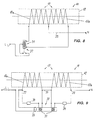
- Fig. 8 shows a circuit diagram of an embodiment in which the heating element 10 is divided into two interconnected sections 17a, 17b. They consist of resistance materials that have a different temperature characteristic of the resistance. They can both have a positive or negative behavior of the resistance coefficient (PTC or NTC), but these then have different sizes or it can be a combination of PTC with NTC or with a largely temperature-neutral material.
- PTC or NTC positive or negative behavior of the resistance coefficient
- the resistance value of the heating element section 17a at room temperature is equal to that of the section 17b.
- the two outer ends of the heating element sections 17a, 17b are connected to a power supply line L1 via a relay coil 31 of a temperature switching device 32 designed as a relay, while a line 33 laid as a center tap between the two heating element sections 17a, 17b is connected to the power pole N.
- the two resistance values change in such a way that when the parts of the relay coil assigned to sections 17a and 17b are wound in opposite directions, a strong switch-off pulse is produced which does not occur in a lower temperature range due to the opposite effect of the two excitation coil halves.
- the relay should preferably be designed so that it does not switch on again automatically after it has been switched off. It should then only be restarted manually after the cause of the trip has been eliminated.
- Fig. 9 shows a circuit diagram of an embodiment in which the rest of the same conditions for the two heating element sections 17a, 17b, the relay, also with oppositely wound excitation coils 31 and self-holding, is not flowed through by the total current of the heating element, but is voltage-actuated.
- the two power supply lines Ll and N (Ll via the switch contact 33 of the relay) are located directly on the connections 22, of which a line 35, which is guided in each case via a resistor 34, is led to one half of the excitation coil while the other ends of the two excitation coil halves are connected to the center tap 35.
- this version requires additional lines, it enables a small relay operated with low currents.
- This version of a temperature switching device uses the heating element itself as a sensor and is therefore ideally coupled to its temperature. According to the invention, however, there are also other options for a good coupling of a temperature protection switch, in which the coupling to the temperature of the heating is preferred, in order to ensure a quick and low-inertia response.
- a simple temperature protection switch which contains a bimetallic spring washer (KLIXON), can be used, in which it is attached, in particular in the overlap area 15 of the inner insulation 13. This is where the "hot spot" of the heating system will be, ensuring a quick response.
- the temperature protection switch can, for example, be attached directly to the outer jacket 21 in this area. Attachment is also possible directly on the outer insulation 19.
- a temperature switch 36 (indicated by dashed lines in Fig. 2), which has a snap switch which is actuated by a reference rod 37 made of material without significant thermal expansion (e.g. ceramic), which is parallel to Radiator axis 38 is guided outside and is attached to the temperature switch 36 at its end opposite to this.
- a reference rod 37 made of material without significant thermal expansion (e.g. ceramic), which is parallel to Radiator axis 38 is guided outside and is attached to the temperature switch 36 at its end opposite to this.
- the expansion of the radiator ie the hollow body 12, is itself used to generate the switch-off movement.
- a capillary tube made of stainless steel is used as the heating element instead of a heating tape. This is wound onto the insulating film in accordance with the heating element 17 and contains an expansion liquid which, when heated by the passage of current through the capillary tube, also heats up and acts on an expansion socket which can be used for switching off but also for control functions.
- an overtemperature protection device 50 in the form of a thermal switch. It has a housing 51 made of insulating material, which contains a base base part 52, the underside of which is directed toward the flow heater 11 and is adapted to the shape thereof, i.e. has an arcuate recess 53 with the radius corresponding to the outer diameter of the hollow body.
- a projection 54 extends from the base base part 52 and a thermal switch 55 is attached to the underside thereof.
- This consists of a bimetal 56 which is fastened on one side by means of a rivet 57 to the underside of the projection 54, while the other side of the bimetal 56 carries a switching contact 58 which cooperates with a corresponding mating contact 59 on the underside of the projection 54.
- the bimetal 56 is a bimetal with crack characteristics, i.e. due to its curved shape, it is designed so that it can assume two stable end positions, between which a snap action occurs.
- the bimetal switch 55 operates with current-carrying bimetal, i.e. the bimetal 56 is connected via the rivet 57 to a connection 61 in the form of a flat tongue, while the mating contact 59 is electrically connected to a bracket 62 which has a substantially tangential connecting tongue 63 (see FIG. 13) which is connected to the Heating element 17 can be welded directly.
- the overtemperature protection device 5 thus forms the connection piece for one side of the heating element 17 and is not a part to be assembled separately.
- bracket 64 which can be welded to the hollow body 12 outside the heated area.
- the conditions for a thermal coupling of an overtemperature protection element are particularly advantageous if the flow heater has a power-related heat capacity of not more than 0.04 s / K in its heated area.
- the performance-related heat capacity mxc / P is measured from m (the mass in kg), c (specific heat capacity in kJ / (kg x K) and P (power of the heating element in kW). If this capacity becomes too large, the switch will respond when running dry, but the excess heat could already damage the heating conductors.
- the heated area possibly including the overtemperature protection device, could be encased, for example by a shrink tube, which is firmly attached to the unit under the influence of heat.
- the outer insulation which preferably consists of a polyimide plastic film, can likewise consist of insulation paper, or else of a coating with a lacquer or PTFE.
- the temperature protection device can have a switch, the contacts of which are irreversibly interrupted by an element which deforms when the temperature rises and possibly melts.
- a switch has become known, for example, from DE-36 33 759 A1.
Landscapes
- Engineering & Computer Science (AREA)
- General Engineering & Computer Science (AREA)
- Chemical & Material Sciences (AREA)
- Thermal Sciences (AREA)
- Combustion & Propulsion (AREA)
- Mechanical Engineering (AREA)
- Physics & Mathematics (AREA)
- Resistance Heating (AREA)
- Rigid Pipes And Flexible Pipes (AREA)
- Instantaneous Water Boilers, Portable Hot-Water Supply Apparatuses, And Control Of Portable Hot-Water Supply Apparatuses (AREA)
- Constitution Of High-Frequency Heating (AREA)
- Electrotherapy Devices (AREA)
- Secondary Cells (AREA)
Applications Claiming Priority (2)
| Application Number | Priority Date | Filing Date | Title |
|---|---|---|---|
| DE4233676A DE4233676A1 (de) | 1992-10-07 | 1992-10-07 | Elektrischer Heizkörper für Medien, insbesondere Durchflußerhitzer |
| DE4233676 | 1992-10-07 |
Publications (2)
| Publication Number | Publication Date |
|---|---|
| EP0591755A1 true EP0591755A1 (fr) | 1994-04-13 |
| EP0591755B1 EP0591755B1 (fr) | 1997-07-23 |
Family
ID=6469819
Family Applications (1)
| Application Number | Title | Priority Date | Filing Date |
|---|---|---|---|
| EP93115214A Expired - Lifetime EP0591755B1 (fr) | 1992-10-07 | 1993-09-22 | Radiateur électrique pour fluides notamment pour dispositifs de chauffage en continu |
Country Status (7)
| Country | Link |
|---|---|
| US (1) | US5434388A (fr) |
| EP (1) | EP0591755B1 (fr) |
| AT (1) | ATE155952T1 (fr) |
| DE (2) | DE4233676A1 (fr) |
| ES (1) | ES2105026T3 (fr) |
| HR (1) | HRP930246A2 (fr) |
| TR (1) | TR28725A (fr) |
Cited By (4)
| Publication number | Priority date | Publication date | Assignee | Title |
|---|---|---|---|---|
| DE19512497C1 (de) * | 1995-04-04 | 1996-07-18 | Tuerk & Hillinger Gmbh | Elektrischer Durchlauferhitzer für flüssige Medien |
| EP1696181A1 (fr) * | 2005-01-20 | 2006-08-30 | The Heating Company BVBA | Radiateur avec un élément de chauffage électrique externe |
| CN103974839A (zh) * | 2011-09-06 | 2014-08-06 | 法雷奥热系统公司 | 用于机动车辆的电加热装置和相关联的空调和/或加热单元 |
| EP3511968A1 (fr) * | 2018-01-16 | 2019-07-17 | Marcel P. Hofsaess | Commutateur dépendant de la température |
Families Citing this family (54)
| Publication number | Priority date | Publication date | Assignee | Title |
|---|---|---|---|---|
| US5848223A (en) * | 1994-05-27 | 1998-12-08 | Steward Plastics, Inc. | Double-walled flexible tubing product with helical support bead and heating conductor and apparatus and method for making |
| DE4420493A1 (de) | 1994-06-12 | 1995-12-14 | Ego Elektro Blanc & Fischer | Elektronisches Durchflußheizelement für Medien |
| ES2103670B1 (es) * | 1994-12-27 | 1998-05-01 | Nugar Bobinajes Sl | Resistencia electrica. |
| DE19505621A1 (de) * | 1995-02-18 | 1996-08-22 | Ego Elektro Blanc & Fischer | Übertemperatursicherung für elektrische Heizeinrichtung |
| DE19605996C2 (de) * | 1996-02-17 | 2000-10-19 | Tuerk & Hillinger Gmbh | Verfahren zur Herstellung elektrischer Durchlauferhitzer für flüssige Medien |
| DE19623570C2 (de) * | 1996-06-13 | 1998-05-28 | Marcel Hofsaes | Temperaturwächter mit einer Kaptonfolie |
| GB2315366B (en) * | 1996-07-12 | 2000-10-18 | Otter Controls Ltd | Improvements relating to thermal controls for liquid heating vessels |
| US5882416A (en) * | 1997-06-19 | 1999-03-16 | Advanced Technology Materials, Inc. | Liquid delivery system, heater apparatus for liquid delivery system, and vaporizer |
| USD415264S (en) * | 1997-12-08 | 1999-10-12 | Sherwood-Templeton Coal Company, Inc. | Water heater |
| US6305923B1 (en) * | 1998-06-12 | 2001-10-23 | Husky Injection Molding Systems Ltd. | Molding system using film heaters and/or sensors |
| US6157777A (en) * | 1998-08-06 | 2000-12-05 | Dekko Heating Technologies, Inc. | Heater assembly for a fluid conduit with an integral heater |
| GB2345597B (en) * | 1999-01-11 | 2003-07-02 | Otter Controls Ltd | Improvements relating to thermal controls |
| US6222166B1 (en) * | 1999-08-09 | 2001-04-24 | Watlow Electric Manufacturing Co. | Aluminum substrate thick film heater |
| US6459854B1 (en) * | 2000-01-24 | 2002-10-01 | Nestec S.A. | Process and module for heating liquid |
| US7158718B2 (en) * | 2000-06-14 | 2007-01-02 | Watlow Electric Manufacturing Company | Electric heating device |
| US6943325B2 (en) * | 2000-06-30 | 2005-09-13 | Balboa Instruments, Inc. | Water heater |
| US7057140B2 (en) * | 2000-06-30 | 2006-06-06 | Balboa Instruments, Inc. | Water heater |
| US6410894B1 (en) * | 2000-10-12 | 2002-06-25 | Watlow Electric Manufacturing Company | Metallic overcoat for thick film heater termination |
| US20040151835A1 (en) * | 2001-02-26 | 2004-08-05 | Mirko Croci | Method for forming a coating film, consisting of carbon nanotubes, on the surface of a substrate |
| DE60227248D1 (de) * | 2002-07-12 | 2008-08-07 | Nestec Sa | Vorrichtung zum Erhitzen einer Flüssigkeit |
| DE10313861A1 (de) * | 2003-03-21 | 2004-09-30 | Bleckmann Gmbh | Vormontierte Anschlussbaugruppe |
| US7206506B2 (en) * | 2004-08-24 | 2007-04-17 | Tankless Systems Worldwide Inc. | Fluid heating system |
| EP1634520A1 (fr) * | 2004-09-13 | 2006-03-15 | Nestec S.A. | Dispositif de chauffage d'un liquide et procede pour chauffer un liquide |
| KR100593628B1 (ko) * | 2005-04-26 | 2006-07-03 | (주)에이오앤 | 단열 히터 재킷 |
| FR2891720B1 (fr) * | 2005-10-06 | 2007-12-14 | Seb Sa | Dispositif de chauffage de liquide pour appareil electromenager. |
| JP2007127318A (ja) * | 2005-11-02 | 2007-05-24 | Nippon Thermostat Co Ltd | 給湯装置 |
| US7818264B2 (en) | 2006-06-19 | 2010-10-19 | Visa U.S.A. Inc. | Track data encryption |
| DE102008010343A1 (de) | 2008-02-14 | 2009-01-02 | E.G.O. Elektro-Gerätebau GmbH | Heizeinrichtung zur Erhitzung von Wasser |
| US8976552B2 (en) * | 2009-03-03 | 2015-03-10 | Gary Hanington | Power supply with integrated linear high voltage multiplier and capacitors therefor |
| US20110008030A1 (en) * | 2009-07-08 | 2011-01-13 | Shimin Luo | Non-metal electric heating system and method, and tankless water heater using the same |
| DE102009042481B4 (de) | 2009-09-24 | 2021-08-05 | Stiebel Eltron Gmbh & Co. Kg | Warmwassergerät |
| CA2779603C (fr) * | 2009-11-16 | 2015-05-12 | Bell Helicopter Textron Inc. | Sous-systeme de secours pour systeme fluidique |
| WO2011137266A1 (fr) * | 2010-04-28 | 2011-11-03 | Watlow Electric Manufacturing Company | Unité de chauffage à flux traversant |
| DE202010006739U1 (de) * | 2010-05-12 | 2010-08-19 | Türk & Hillinger GmbH | Durchlauferhitzer |
| CN201839457U (zh) * | 2010-05-24 | 2011-05-18 | 小田(中山)实业有限公司 | 发热器以及即热式电热水机 |
| DE102011005179A1 (de) * | 2011-03-07 | 2012-09-13 | Eichenauer Heizelemente Gmbh & Co. Kg | Flächenheizeinrichtung und Verfahren zum Herstellen einer Flächenheizeinrichtung |
| PL2753202T3 (pl) | 2011-09-06 | 2016-11-30 | Podgrzewanie materiału przeznaczonego do palenia | |
| FR2979692B1 (fr) | 2011-09-06 | 2018-06-15 | Valeo Systemes Thermiques | Dispositif de chauffage electrique pour vehicule automobile, et appareil de chauffage et/ou de climatisation associe |
| EP3892125A3 (fr) | 2011-09-06 | 2022-01-05 | Nicoventures Trading Limited | Chauffage de substance fumable |
| GB201207039D0 (en) | 2012-04-23 | 2012-06-06 | British American Tobacco Co | Heating smokeable material |
| US20150219361A1 (en) * | 2012-08-16 | 2015-08-06 | Top Electric Appliances Industrial Ltd | Device for heating and/or vaporizing a fluid such as water |
| DE102013102378A1 (de) | 2013-03-11 | 2014-09-11 | GC-heat Gebhard GmbH & Co.KG | Heizeinrichtung zum außenseitigen Beheizen eines rohrförmigen Bauteiles |
| US20150297029A1 (en) * | 2014-04-16 | 2015-10-22 | Spectrum Brands, Inc. | Cooking appliance using thin-film heating element |
| US20160363367A1 (en) * | 2015-06-12 | 2016-12-15 | General Electric Company | Component for a refrigerator appliance having an integrated heater |
| UA114216U (xx) * | 2015-06-30 | 2017-03-10 | Нагрівач | |
| US10539320B1 (en) * | 2015-08-25 | 2020-01-21 | The United States Of America As Represented By The Secretary Of The Army | Combustion aerosol generator system |
| US11924930B2 (en) | 2015-08-31 | 2024-03-05 | Nicoventures Trading Limited | Article for use with apparatus for heating smokable material |
| US20170055584A1 (en) | 2015-08-31 | 2017-03-02 | British American Tobacco (Investments) Limited | Article for use with apparatus for heating smokable material |
| US20170119046A1 (en) | 2015-10-30 | 2017-05-04 | British American Tobacco (Investments) Limited | Apparatus for Heating Smokable Material |
| DE102017000438A1 (de) * | 2017-01-19 | 2018-07-19 | Stiebel Eltron Gmbh & Co. Kg | Sicherheitsvorrichtung zum Notabschalten eines elektrischen Durchlauferhitzers |
| KR20200144560A (ko) * | 2018-04-20 | 2020-12-29 | 탐 리차즈, 인코포레이티드. | 인라인 고순도 케미컬 히터 |
| TR201819096A2 (tr) * | 2018-12-11 | 2019-01-21 | Mtl Group Makine Sihhi Ve Isi Tesisat Malzeme Cihazlari Ithalat Ihracat Sanayi Ve Ticaret Ltd Sirket | Kapton kaplamali rezi̇stans i̇çeren isitici modül |
| CN114761736B (zh) * | 2019-12-04 | 2024-06-14 | 格兰富控股公司 | 加热系统和制造加热系统的方法 |
| US12313297B2 (en) * | 2020-01-27 | 2025-05-27 | Lexmark International, Inc. | Thin-walled tube heater for fluid |
Citations (2)
| Publication number | Priority date | Publication date | Assignee | Title |
|---|---|---|---|---|
| CH220465A (de) * | 1941-06-17 | 1942-04-15 | Waespe Zwickl Wilhelm | Vorrichtung zum Verhüten des Einfrierens von Flüssigkeitsleitungen, insbesondere von Wasserleitungen. |
| DE1806721A1 (de) * | 1968-11-02 | 1970-05-21 | Siemens Elektrogeraete Gmbh | Elektrischer Durchlauferhitzer |
Family Cites Families (18)
| Publication number | Priority date | Publication date | Assignee | Title |
|---|---|---|---|---|
| US3315703A (en) * | 1967-04-25 | Matthews etal composite tubing product | ||
| US2473560A (en) * | 1946-08-29 | 1949-06-21 | Edward S Bagley | Unit water heater |
| US2665364A (en) * | 1951-04-16 | 1954-01-05 | American Electrical Heater Co | Electrically heated tool |
| US3019325A (en) * | 1958-12-15 | 1962-01-30 | Frank S Clouse | Fuel heating device |
| US3139518A (en) * | 1962-11-08 | 1964-06-30 | Northwest Ind Ltd | Heating element |
| US3727029A (en) * | 1964-07-01 | 1973-04-10 | Moore & Co Samuel | Composite electrically heated tubing product |
| DE1690677A1 (de) * | 1968-02-28 | 1971-06-09 | Stiebel Werke Gmbh & Co Dr | Elektrischer Durchlauferhitzer |
| DE7020539U (de) * | 1970-05-27 | 1970-09-03 | Schmidt Eltrolued & Co E | Abschaltvorrichtung fuer tauchsieder. |
| DE2552625A1 (de) * | 1975-11-24 | 1977-06-02 | Elpag Ag Chur | Vorrichtung zur verhinderung einer ueberhitzung von elektrisch beheizten geraeten |
| US4455474A (en) * | 1981-11-27 | 1984-06-19 | Nordson Corporation | Thermally insulated electrically heated hose for transmitting hot liquids |
| DE3221348A1 (de) * | 1982-06-05 | 1983-12-08 | E.G.O. Elektro-Geräte Blanc u. Fischer, 7519 Oberderdingen | Heizelement mit zylindrischer wandung |
| GB8524487D0 (en) * | 1985-10-04 | 1985-11-06 | Strix Ltd | Thermally-sensitive controls |
| DE8701656U1 (de) * | 1987-02-04 | 1987-03-19 | Türk & Hillinger GmbH, 7200 Tuttlingen | Elektrischer Durchlauferhitzer mit Kaltleiterheizelementen |
| DE8715851U1 (de) * | 1987-11-30 | 1988-02-18 | Elpag Ag Chur, Chur | Rohrheizkörper mit einer Überlastungssicherung |
| DE3903649C1 (en) * | 1989-02-08 | 1990-04-12 | Tuerk & Hillinger Gmbh, 7200 Tuttlingen, De | Electric flow heater for liquids |
| DE4012643A1 (de) * | 1990-04-20 | 1990-12-06 | Stefan Schaefer | Verfahren und anordnung von folienartigen heizelementen fuer wassererwaermende geraete, insbesondere durchlauferhitzer |
| DE4034611A1 (de) * | 1990-10-31 | 1992-05-07 | Stiebel Eltron Gmbh & Co Kg | Elektrischer durchlauferhitzer |
| DE9105855U1 (de) * | 1991-05-10 | 1991-12-19 | Licentia Patent-Verwaltungs-Gmbh, 6000 Frankfurt | Elektrischer Durchlauferhitzer für Haushaltsgeräte |
-
1992
- 1992-10-07 DE DE4233676A patent/DE4233676A1/de not_active Withdrawn
-
1993
- 1993-03-02 HR HR930246A patent/HRP930246A2/xx not_active Application Discontinuation
- 1993-09-22 EP EP93115214A patent/EP0591755B1/fr not_active Expired - Lifetime
- 1993-09-22 AT AT93115214T patent/ATE155952T1/de not_active IP Right Cessation
- 1993-09-22 DE DE59306960T patent/DE59306960D1/de not_active Expired - Fee Related
- 1993-09-22 ES ES93115214T patent/ES2105026T3/es not_active Expired - Lifetime
- 1993-10-05 TR TR00903/93A patent/TR28725A/xx unknown
- 1993-10-07 US US08/132,793 patent/US5434388A/en not_active Expired - Fee Related
Patent Citations (2)
| Publication number | Priority date | Publication date | Assignee | Title |
|---|---|---|---|---|
| CH220465A (de) * | 1941-06-17 | 1942-04-15 | Waespe Zwickl Wilhelm | Vorrichtung zum Verhüten des Einfrierens von Flüssigkeitsleitungen, insbesondere von Wasserleitungen. |
| DE1806721A1 (de) * | 1968-11-02 | 1970-05-21 | Siemens Elektrogeraete Gmbh | Elektrischer Durchlauferhitzer |
Cited By (7)
| Publication number | Priority date | Publication date | Assignee | Title |
|---|---|---|---|---|
| DE19512497C1 (de) * | 1995-04-04 | 1996-07-18 | Tuerk & Hillinger Gmbh | Elektrischer Durchlauferhitzer für flüssige Medien |
| EP1696181A1 (fr) * | 2005-01-20 | 2006-08-30 | The Heating Company BVBA | Radiateur avec un élément de chauffage électrique externe |
| CN103974839A (zh) * | 2011-09-06 | 2014-08-06 | 法雷奥热系统公司 | 用于机动车辆的电加热装置和相关联的空调和/或加热单元 |
| CN103974839B (zh) * | 2011-09-06 | 2016-10-12 | 法雷奥热系统公司 | 用于机动车辆的电加热装置和相关联的空调和/或加热单元 |
| EP3511968A1 (fr) * | 2018-01-16 | 2019-07-17 | Marcel P. Hofsaess | Commutateur dépendant de la température |
| CN110047698A (zh) * | 2018-01-16 | 2019-07-23 | 马赛尔·P·霍夫萨埃斯 | 温控开关 |
| US10861662B2 (en) | 2018-01-16 | 2020-12-08 | Marcel P. HOFSAESS | Temperature-dependent switch |
Also Published As
| Publication number | Publication date |
|---|---|
| HRP930246A2 (en) | 1995-12-31 |
| DE4233676A1 (de) | 1994-04-14 |
| ATE155952T1 (de) | 1997-08-15 |
| ES2105026T3 (es) | 1997-10-16 |
| DE59306960D1 (de) | 1997-08-28 |
| TR28725A (tr) | 1997-02-20 |
| US5434388A (en) | 1995-07-18 |
| EP0591755B1 (fr) | 1997-07-23 |
Similar Documents
| Publication | Publication Date | Title |
|---|---|---|
| EP0591755B1 (fr) | Radiateur électrique pour fluides notamment pour dispositifs de chauffage en continu | |
| EP0342441B1 (fr) | Dispositif de commutation sensible à la température | |
| DE19703758C2 (de) | Temperaturschalter | |
| DE2948281C2 (de) | Elektrische Schaltung und Schaltungsschutzeinrichtung | |
| DE69534857T2 (de) | Polymeres widerstandsheizelement | |
| EP2846344B1 (fr) | Commutateur thermique | |
| EP0557744A1 (fr) | Interrupteur thermique | |
| AT402983B (de) | Temperaturwächter | |
| EP0951040B2 (fr) | Interrupteur à commande thermique | |
| DE4300909C2 (de) | Thermischer Auslöser, insbesondere für einen Leitungsschutzschalter | |
| DE69505884T2 (de) | Geräte mit Widerstandselemeten und Temperaturschutzvorrichtung zum Gebrauch dafür | |
| CH671649A5 (fr) | ||
| EP0727799B1 (fr) | Dispositif de chauffage comportant un élément électrique de chauffage et une protection contre suréchauffement | |
| DE3338799A1 (de) | Thermischer ausloeser | |
| EP2348251B1 (fr) | Dispositif de chauffage d'un liquide et procédé de fabrication d'un dispositif de chauffage pour le chauffage d'un liquide | |
| EP0621738B1 (fr) | Dispositif de sécurité pour un élément de chauffage électrique contre une réduction inadmissible du transfer de chaleur | |
| EP0793399B1 (fr) | Elément de chauffage à autorégulation | |
| DE2458952C3 (de) | Thermischer Schutzschalter | |
| DE1640197A1 (de) | Bimetallschalter | |
| DE69129468T2 (de) | Elektrischer rohrheizkörper mit einer temperaturkontrolleinrichtung | |
| DE3331847A1 (de) | Kabeltrommel | |
| DE19512497C1 (de) | Elektrischer Durchlauferhitzer für flüssige Medien | |
| DE4205699A1 (de) | Vorrichtung zum Schützen eines Geräts | |
| DE8330704U1 (de) | Thermischer Auslöser | |
| AT207930B (de) | Heizelement zur Beheizung des Bimetalles bei thermischen Schaltvorrichtungen mit Bimetallauslösung |
Legal Events
| Date | Code | Title | Description |
|---|---|---|---|
| PUAI | Public reference made under article 153(3) epc to a published international application that has entered the european phase |
Free format text: ORIGINAL CODE: 0009012 |
|
| 17P | Request for examination filed |
Effective date: 19940215 |
|
| AK | Designated contracting states |
Kind code of ref document: A1 Designated state(s): AT DE ES FR GB IT SE |
|
| RAP1 | Party data changed (applicant data changed or rights of an application transferred) |
Owner name: E.G.O. ELEKTRO-GERAETE BLANC UND FISCHER GMBH & CO |
|
| 17Q | First examination report despatched |
Effective date: 19950117 |
|
| GRAG | Despatch of communication of intention to grant |
Free format text: ORIGINAL CODE: EPIDOS AGRA |
|
| RTI1 | Title (correction) | ||
| RAP1 | Party data changed (applicant data changed or rights of an application transferred) |
Owner name: E.G.O. ELEKTRO-GERAETEBAU GMBH |
|
| GRAH | Despatch of communication of intention to grant a patent |
Free format text: ORIGINAL CODE: EPIDOS IGRA |
|
| GRAH | Despatch of communication of intention to grant a patent |
Free format text: ORIGINAL CODE: EPIDOS IGRA |
|
| GRAA | (expected) grant |
Free format text: ORIGINAL CODE: 0009210 |
|
| AK | Designated contracting states |
Kind code of ref document: B1 Designated state(s): AT DE ES FR GB IT SE |
|
| PG25 | Lapsed in a contracting state [announced via postgrant information from national office to epo] |
Ref country code: GB Effective date: 19970723 |
|
| REF | Corresponds to: |
Ref document number: 155952 Country of ref document: AT Date of ref document: 19970815 Kind code of ref document: T |
|
| REF | Corresponds to: |
Ref document number: 59306960 Country of ref document: DE Date of ref document: 19970828 |
|
| ITF | It: translation for a ep patent filed | ||
| REG | Reference to a national code |
Ref country code: ES Ref legal event code: FG2A Ref document number: 2105026 Country of ref document: ES Kind code of ref document: T3 |
|
| ET | Fr: translation filed | ||
| GBV | Gb: ep patent (uk) treated as always having been void in accordance with gb section 77(7)/1977 [no translation filed] |
Effective date: 19970723 |
|
| PLBE | No opposition filed within time limit |
Free format text: ORIGINAL CODE: 0009261 |
|
| 26N | No opposition filed | ||
| PGFP | Annual fee paid to national office [announced via postgrant information from national office to epo] |
Ref country code: ES Payment date: 19990917 Year of fee payment: 7 |
|
| PGFP | Annual fee paid to national office [announced via postgrant information from national office to epo] |
Ref country code: SE Payment date: 19990921 Year of fee payment: 7 Ref country code: AT Payment date: 19990921 Year of fee payment: 7 |
|
| PG25 | Lapsed in a contracting state [announced via postgrant information from national office to epo] |
Ref country code: AT Free format text: LAPSE BECAUSE OF NON-PAYMENT OF DUE FEES Effective date: 20000922 |
|
| PG25 | Lapsed in a contracting state [announced via postgrant information from national office to epo] |
Ref country code: ES Free format text: LAPSE BECAUSE OF NON-PAYMENT OF DUE FEES Effective date: 20000923 |
|
| PG25 | Lapsed in a contracting state [announced via postgrant information from national office to epo] |
Ref country code: SE Free format text: THE PATENT HAS BEEN ANNULLED BY A DECISION OF A NATIONAL AUTHORITY Effective date: 20000929 |
|
| EUG | Se: european patent has lapsed |
Ref document number: 93115214.4 |
|
| PGFP | Annual fee paid to national office [announced via postgrant information from national office to epo] |
Ref country code: FR Payment date: 20010917 Year of fee payment: 9 |
|
| PGFP | Annual fee paid to national office [announced via postgrant information from national office to epo] |
Ref country code: DE Payment date: 20011116 Year of fee payment: 9 |
|
| PG25 | Lapsed in a contracting state [announced via postgrant information from national office to epo] |
Ref country code: DE Free format text: LAPSE BECAUSE OF NON-PAYMENT OF DUE FEES Effective date: 20030401 |
|
| PG25 | Lapsed in a contracting state [announced via postgrant information from national office to epo] |
Ref country code: FR Free format text: LAPSE BECAUSE OF NON-PAYMENT OF DUE FEES Effective date: 20030603 |
|
| REG | Reference to a national code |
Ref country code: FR Ref legal event code: ST |
|
| REG | Reference to a national code |
Ref country code: ES Ref legal event code: FD2A Effective date: 20011011 |
|
| PG25 | Lapsed in a contracting state [announced via postgrant information from national office to epo] |
Ref country code: IT Free format text: LAPSE BECAUSE OF NON-PAYMENT OF DUE FEES;WARNING: LAPSES OF ITALIAN PATENTS WITH EFFECTIVE DATE BEFORE 2007 MAY HAVE OCCURRED AT ANY TIME BEFORE 2007. THE CORRECT EFFECTIVE DATE MAY BE DIFFERENT FROM THE ONE RECORDED. Effective date: 20050922 |