EP0591901A1 - Guidage pour éléments téléscopiques et cylindriques et une colonne comprenant ceux-ci - Google Patents
Guidage pour éléments téléscopiques et cylindriques et une colonne comprenant ceux-ci Download PDFInfo
- Publication number
- EP0591901A1 EP0591901A1 EP93116024A EP93116024A EP0591901A1 EP 0591901 A1 EP0591901 A1 EP 0591901A1 EP 93116024 A EP93116024 A EP 93116024A EP 93116024 A EP93116024 A EP 93116024A EP 0591901 A1 EP0591901 A1 EP 0591901A1
- Authority
- EP
- European Patent Office
- Prior art keywords
- sleeve body
- guiding sleeve
- guiding
- main sleeve
- set forth
- Prior art date
- Legal status (The legal status is an assumption and is not a legal conclusion. Google has not performed a legal analysis and makes no representation as to the accuracy of the status listed.)
- Granted
Links
- 239000000463 material Substances 0.000 claims description 21
- 229920003023 plastic Polymers 0.000 claims description 8
- 239000004033 plastic Substances 0.000 claims description 8
- 238000003780 insertion Methods 0.000 claims description 7
- 230000037431 insertion Effects 0.000 claims description 7
- 238000004519 manufacturing process Methods 0.000 claims description 4
- 230000004323 axial length Effects 0.000 claims description 3
- 238000000465 moulding Methods 0.000 description 4
- 239000002184 metal Substances 0.000 description 2
- FGRBYDKOBBBPOI-UHFFFAOYSA-N 10,10-dioxo-2-[4-(N-phenylanilino)phenyl]thioxanthen-9-one Chemical compound O=C1c2ccccc2S(=O)(=O)c2ccc(cc12)-c1ccc(cc1)N(c1ccccc1)c1ccccc1 FGRBYDKOBBBPOI-UHFFFAOYSA-N 0.000 description 1
- 230000001427 coherent effect Effects 0.000 description 1
- 230000000694 effects Effects 0.000 description 1
- 239000013013 elastic material Substances 0.000 description 1
- 238000001746 injection moulding Methods 0.000 description 1
- 239000007788 liquid Substances 0.000 description 1
- 238000000034 method Methods 0.000 description 1
- 239000002245 particle Substances 0.000 description 1
- 238000007493 shaping process Methods 0.000 description 1
Images

Classifications
-
- F—MECHANICAL ENGINEERING; LIGHTING; HEATING; WEAPONS; BLASTING
- F16—ENGINEERING ELEMENTS AND UNITS; GENERAL MEASURES FOR PRODUCING AND MAINTAINING EFFECTIVE FUNCTIONING OF MACHINES OR INSTALLATIONS; THERMAL INSULATION IN GENERAL
- F16F—SPRINGS; SHOCK-ABSORBERS; MEANS FOR DAMPING VIBRATION
- F16F9/00—Springs, vibration-dampers, shock-absorbers, or similarly-constructed movement-dampers using a fluid or the equivalent as damping medium
- F16F9/02—Springs, vibration-dampers, shock-absorbers, or similarly-constructed movement-dampers using a fluid or the equivalent as damping medium using gas only or vacuum
- F16F9/0209—Telescopic
- F16F9/0245—Means for adjusting the length of, or for locking, the spring or dampers
-
- A—HUMAN NECESSITIES
- A47—FURNITURE; DOMESTIC ARTICLES OR APPLIANCES; COFFEE MILLS; SPICE MILLS; SUCTION CLEANERS IN GENERAL
- A47B—TABLES; DESKS; OFFICE FURNITURE; CABINETS; DRAWERS; GENERAL DETAILS OF FURNITURE
- A47B9/00—Tables with tops of variable height
- A47B9/10—Tables with tops of variable height with vertically-acting fluid cylinder
-
- A—HUMAN NECESSITIES
- A47—FURNITURE; DOMESTIC ARTICLES OR APPLIANCES; COFFEE MILLS; SPICE MILLS; SUCTION CLEANERS IN GENERAL
- A47C—CHAIRS; SOFAS; BEDS
- A47C3/00—Chairs characterised by structural features; Chairs or stools with rotatable or vertically-adjustable seats
- A47C3/20—Chairs or stools with vertically-adjustable seats
- A47C3/30—Chairs or stools with vertically-adjustable seats with vertically-acting fluid cylinder
-
- F—MECHANICAL ENGINEERING; LIGHTING; HEATING; WEAPONS; BLASTING
- F16—ENGINEERING ELEMENTS AND UNITS; GENERAL MEASURES FOR PRODUCING AND MAINTAINING EFFECTIVE FUNCTIONING OF MACHINES OR INSTALLATIONS; THERMAL INSULATION IN GENERAL
- F16F—SPRINGS; SHOCK-ABSORBERS; MEANS FOR DAMPING VIBRATION
- F16F9/00—Springs, vibration-dampers, shock-absorbers, or similarly-constructed movement-dampers using a fluid or the equivalent as damping medium
- F16F9/32—Details
- F16F9/36—Special sealings, including sealings or guides for piston-rods
- F16F9/366—Special sealings, including sealings or guides for piston-rods functioning as guide only, e.g. bushings
Definitions
- the present invention relates to a guide means for telescoping cylindrical parts, especially of a randomly blockable gas spring, whose cylindrical outer face is slidingly arranged within a guiding sleeve unit which is connected to a base tube, said guiding sleeve unit comprising a main sleeve body, wherein at least one guiding sleeve body is arranged.
- the guiding sleeve unit for a gas spring comprises a central bracing tube wherein guiding sleeve bodies are arranged in spaced relationship with respect to each other, both said bracing tube and said guiding sleeve bodies being surrounded by a carrying bush.
- the guiding sleeve bodies are held within the bracing tube by force fit or tight fit: consequently, there is principally involved a premounted one-piece guiding sleeve unit which entails the disadvantage that, when assembled, corresponding refinishing operations become necessary and that expensive, precise component parts are required in order to achieve tight fit or force fit.
- guide means comprising a guiding sleeve unit pressed into the base tube.
- the guiding sleeve unit includes a receiving bush with at least one joint bush being located therein and being angularly movable within a corresponding groove; this joint bush consists substantially of a non-elastic material.
- the joint bush carries a bearing bush and is mounted to have clearance to the blockable gas spring displaceably arranged within the bearing bush. For functional efficiency reasons, such clearance cannot be established within desired limits at low cost. Too large a clearance entails the disadvantage that the user gets an unpleasant feeling and that the chair column tends to cause noises.
- the present invention suggests that the main sleeve body and the guiding sleeve body are provided on their surfaces facing each other with at least one projection and/or at least one recess engaging each other.
- a guiding sleeve body is inserted at the upper and lower end of the main sleeve body, the projections and recesses thereby forming a simple plug connection in order to fasten the guiding sleeve bodies in axial direction.
- One may use simple low-cost injection-moulded parts so that not only the number of component parts is reduced but also a simple and fast mounting becomes possible.
- the guiding sleeve bodies may have such dimensions that the guiding sleeve unit comsisitng of the main sleeve body and the guiding sleeve bodies can be pressed into a metal base tube.
- An especially preferred embodiment provides that the main sleeve body has only recesses and the guiding sleeve bodies have only projections. This entails the advantage that the guiding sleeve bodies have no interruptions at all on their entire bearing faces so that a precalibration of the inner diameter of the guiding sleeve bodies is possible.
- An especially preferred embodiment provides that the recesses are provided in an axial front area of the main sleeve body.
- the projections when seen in mounting direction, have a face of steadily enlarging diameter. This face begins at the outer diameter of the guiding sleeve body and enlarges correspondingly so that these faces serve as entry guide slopes during the mounting operation by first forming a radially inwardly directed bend and then springing back to their normal position after having reached the recesses. Such a spring catch connection can no longer be loosened after insertion of the gas srping in its assembled state.
- the present invention suggests that on the side opposite to the mounting direction the projections have a face extending approximately rectangularly to the axis of the bearing.
- the main sleeve body and the guiding sleeve body consist of different materials. It is advantageous to make the guiding sleeve bodies from a material from which anti-friction sliding bearings are made. By using exclusively plastic materials for the guiding sleeve bodies and the main sleeve body, a backlash-free and low-friction guidance is achieved to guide the gas spring axially, radially and cardanically.
- Another preferred embodiment suggests that the guiding sleeve body has been precalibrated. Thereby, the assembling operation will be easy and quick; the spring catch connection as a whole can be pressed into the metal base tube, and no refinishing operations will have to be done.
- the present invention refers to a column unit comprising a base tube having an axis, a first end and a second end. Support means are provided adjacent the second end.
- a height adjusting unit is provided partially inside the base tube.
- This height adjusting unit has a first height adjustment component extending along the axis inward and outward of the first end of the base tube and further has a second height adjustment component axially movable with respect to the first height adjustment component.
- the second height adjustment component is lockable in selected axial positions with respect to the first height adjustment component.
- the second height adjustment component is substantially axially fixed with respect to the support means.
- the first height adjustment component has a substantially cylindrical external surface along at least a part of its axial length.
- the base tube is provided adjacent its first end with a guiding sleeve unit.
- the first height adjustment component is slidingly guided for at least one of axial and rotational movement by the guiding sleeve unit.
- the guiding sleeve unit comprises a main sleeve body and at least one guiding sleeve body substantially radially inside of the main sleeve body and slidingly engaging the cylindrical external surface of the first height adjustment component.
- the at least one guiding sleeve body is axially secured with respect to the main sleeve body by snapping engagement means of the main sleeve body and the guiding sleeve body snappingly engaging each other in response to axial positioning of said guiding sleeve body with respect to the main sleeve body.
- the column unit is preferably used as a height-adjustable chair column unit.
- the height adjusting unit is preferably a hydraulically or pneumatically lockable unit, such as a gas spring, which gas spring comprises a cylinder, a piston rod, a piston member connected with the piston rod inside the cylinder, a pair of working chambers on both sides of the piston member inside the cylinder and a flow passage connecting the working chambers with a valve unit permitting to selectively open or close said flow passage.
- a gas srping is e.g. shown in DE-OS 36 27 138 and the corresponding U.S. Patent 4,848,524.
- hydropneumatic units may be used as height adjustment units in which liquid filled working chambers are provided adjacent the piston member, and one of the working chambers is adjacent a volume of pressurized gas.
- hydraulic or pneumatic height adjustment units one can continuously vary the effective length by opening the valve unit and fix a desired length by subsequent closing of the valve unit.
- the guiding sleeve body may be located axially adjacent at least one end of the main sleeve body, e. g. the guiding sleeve body may be provided adjacent a first end of the main sleeve body which is more remote from the second end of the base tube.
- respective guiding sleeve bodies may be provided adjacent both ends of the main sleeve body.
- the main sleeve body may have radially outer surface means radially engaged with an internal surface of the base tube.
- the main sleeve body may be axially fixed with respect to the base tube.
- the main sleeve body may be axially fixed with respect to the base tube against movement toward the second end thereof by abutment means of the main sleeve body engaging the second end of the base tube.
- the main sleeve body may be axially secured against movement away from the second end of the base tube by releasable securing means.
- the at least one guiding sleeve body comprises a substantially cylindrical guiding tube member with an inner circumferential guiding surface slidingly engaging the the substantially cylindrical external surface of the first height adjustment component and an outer circumferential surface adjacent an inner substantially cylindrical surface of the main sleeve body.
- the substantially cylindrical guiding tube member may be provided adjacent a respective end of the main sleeve body with at least one radially outward projecting positioning projection. This positioning projection may engage into a respective recess of the main sleeve body axially adjacent a respective end of the main sleeve body.
- the guiding sleeve body is circumferentially positioned with respect to the main sleeve body.
- the main sleeve body may be secured against rotation with respect to the base tube. Under these circumstances, rotation is only possible at the interface between the first height adjustment component and the guiding tube member, where one can easily select a reduced friction providing a desired frictional torque.
- the at least one projection can also be provided by the main sleeve body, and correspondingly, the recess may be provided by the guiding sleeve body. It is preferred, however, to have the projection or the projections on the radially outer side of the guiding sleeve body in order to have the very best sliding behaviour between the first height adjustment component and the guiding sleeve body. In this case, a precalibration of the guiding sleeve body is easily possible with the advantageous result that after assembling the guiding sleeve body and the main sleeve body and also after inserting this preassembly into the base tube no further calibration of the inner circumferential guiding surface of the guiding sleeve body is necessary.
- the snapping engagement means of one of the main sleeve body and the at least one guiding sleeve body may comprise sloped defelection face means inclined with respect to the axis and snapping shoulder means adjacent an axial end of the sloped deflection face means.
- the snapping engagement means of the other one of the main sleeve body and the guiding sleeve body may be resiliently deflectable by engagement with the sloped deflection face means in response to an axial positioning movement of the guiding sleeve body with respect to the main sleeve body and engageable behind the shoulder means in an operational position of the guiding sleeve body with respect to the main sleeve body.
- the at least one positioning projection of the guiding sleeve body may be provided with the sloped deflection face means and the snapping shoulder means.
- the recess may be provided with a radially inward directed engagement web deflectable by the sloped deflection face means in response to axially approaching the guiding sleeve body to an operational position of the guiding sleeve body with respect to the main sleeve body. Then, the engagement web may snap behind the shoulder face means, when the operational position is achieved.
- the snapping engagement means may be provided circumferentially outside the at least one positioning projection and the respective recess, respectively, adjacent respective axial ends of the main sleeve body and the guiding sleeve body.
- This alternative design is preferably used for positioning a guiding sleeve body at the lower end of the main sleeve body, whereas the snapping engagement between the positioning projection and the recess is preferably used for a guiding sleeve body inserted at the upper end of the main sleeve body.
- the main sleeve body and the guiding sleeve body may be provided with abutment means abutting each other, when the respective snapping engagement means have snappingly engaged each other.
- the at least one guiding sleeve body can be easily fixed in both axial direction with respect to the main sleeve body.
- the main sleeve body and the guiding sleeve body are preferably made of plastics material, particularly by injection moulding.
- plastics material needed for moulding the main sleeve body and the at least one guiding sleeve body
- all those usual measures may be used which allow the respective moulding tools to be manufactured in a most easy and economic way.
- the main sleeve body and the guiding sleeve body may be made of different plastics material.
- the guiding sleeve body may be made of a material having improved sliding behaviour with respect to the substantially cylindrical external surface of the first height adjustment component. As a result of such a design, the total cost for manufacturing the guiding sleeve unit are considerably reduced taking into consideration that the material with the best sliding behaviour is generally more expensive than other materials.
- a material of desired high mechanical stability for the main sleeve body can be combined with a material of best sliding behaviour for the guiding sleeve bodies.
- the guiding sleeve body may be made of homogenous material. It may be mixed, however, also with particles providing the desired sliding properties.
- the guiding sleeve body may be made of layers of different materials with the radially innermost layer being made of the material having best sliding properties.
- the guiding sleeve body, the main sleeve body and the base tube may be dimensioned with respect to each other in radial dimensions such that even under consideration of manufacturing tolerances radial play of the first height adjustment component with respect to the base tube is substantially avoided, on the one hand, and clamping of the first height adjustment component with respect to the guiding sleeve body is avoided, on the other hand, such that no further calibration of the inner circumferential surface of the guiding sleeve body is necessary after insertion into the base tube.
- both the main sleeve body and the at least one guiding sleeve body have relatively simple shape which can easily be produced.
- the simple shapes of the sleeve bodies allow to use moulding tools of equally simple shape which can be manufactured with high precision at low cost.
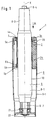
- Fig. 1 shows and describes the guiding sleeve unit 1 for the guidance of telescoping cylindrical parts of a chair column.
- the chair column consists of a gas spring 8 whose downwardly directed piston rod 8-2 is axially fastened in a bottom portion of a base tube 9 but is movable in circumferential direction.
- the base tube 9 is provided with the guiding sleeve unit 1;
- the guiding sleeve unit 1 consists of one main sleeve body 2 and two guiding sleeve bodies 3a and 3b.
- the cylindrical outer face 10 of the gas spring cylinder 8-1 makes a sliding movement when the gas spring 8 is vertically adjusted or when it is elastically compressed. It is, as shown in Fig. 1, easily possible to seccessively arrange a plurality of guiding sleeve bodies within the main sleeve body 2.
- the main sleeve body 2 has in its two terminal portions recesses 5a and 5b into which projections 4a and 4b of the guiding sleeve bodies 3a and 3b engage.
- an axially coherent guiding sleeve unit 1 is obtained which cannot be disassembled after the mounting of the gas spring 8; in this guiding sleeve unit, the guiding sleeve bodies 3a,3b are undetachably held in the main sleeve body 2.
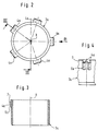
- Figs. 2 to 4 show a guiding sleeve body 3a as a component part. In Fig. 2, a plurality of projections 4a are peripherally distributed.
- the projections may be arranged pairwise adjacent each other.
- Fig. 3 shows the sloped face 6awhich serves as entry help for the axial insertion into the main sleeve body 2 of Fig. 1, the face 7 which is approximately perpendicular to the axis X serves to achieve axial lock when the recesses 5a in the main sleeve body 2 have been reached and the projections 4a have thereafter come to engagement.
- the rectangularly extending face 7 engages either behind a counterface of the main sleeve body 2 or of the flanged end portion of the base tube 9 so that disassembling or loosening of the guiding sleeve body 3 is not possible when the gas spring 8 is in the assembled state.
- Figs. 5 to 8 show the main sleeve body 2.
- the terminal portions of this main sleeve body 2 are provided with recesses 5a and 5b which correspond to the projections 4a of the guiding sleeve body 3a and the projections 4b of the guiding sleeve body 3b.
- the main sleeve body 2 may be made of full material as illustrated in Fig. 2.
- Fig. 5 shows that the section is made through radially outward projecting ribs of a main sleeve body, which ribs serve to obtain a considerable overall thickness of the main sleeve body 2 in radial direction while maintaining the need of plastics material small.
- the embodiment with such ribs is shown particularly in Figs. 7 and 8.
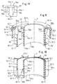
- FIG. 9, 10 and 11 Further details can be seen from Figs. 9, 10 and 11 in which the main sleeve body and the guiding sleeve bodies are shown in more detail.
- the main sleeve body 102 comprises a radially inner shell 102-1 and a radially outer shell 102-2.
- the shell 102-1 extends along the total axial length of the guiding sleeve unit 1 as shown in Fig. 1.
- the radially outer shell 102-2 extends only over an upper part of the guiding sleeve unit 1 as shown in Fig. 1.
- the radially inner shell 102-1 and the radially outer shell 102-2 are interconnected by ribs 102-3 which are substantially parallel to planes containing the axis X.
- the radially outer edges 102-4 of the ribs 102-3 are flush with the radially outer surface 102-5 of the shell 102-2.
- the radially outer edges 102-4 of the ribs 102-3 and the radially outer surface 102-5 of the radially outer shell 102-2 are in centering contact with the radially inner circumferential surface 9-1 of the base tube 9 as shown in Fig. 1.
- the radially inner shell 102-1 and the radially outer shell 102-2 are bridged by an integral terminal ring 102-6, which abuts by a face 102-14 the upper end of the base tube 9.
- an upper guiding sleeve body 103a is an upper guiding sleeve body 103a.
- This upper guiding sleeve body 103a comprises a guiding tube 103a1 which is provided with radial projections 104a:
- the radial projections 104a are shaped for engagement into recesses 105a. These recesses 105a are provided in the radially inner shell 102-1 and in the terminal ring 102-6 of the main sleeve body 102.
- the projections 104a are substantially U-shaped as shown in Fig. 11 with two legs 104a-1 and a middle portion 104a-2.
- the legs 104a-1 are provided with sloped faces 106a. At the upper ends of the sloped faces 106a there are provided shoulder faces 107.
- the upper guiding sleeve body 103a is inserted into the main sleeve body 102 in axial direction X from above with the projections 104a being angularly positioned such as to find into the respective recesses 105a.
- the sloped faces 106a are during this axial approach engaged with the edges 102-7 of the recesses 105a, which edges 102-7 are provided by the terminal ring 102-6.
- the guiding sleeve body 103a is locked against upward movement with respect to the main sleeve body 102. Until this snapping effect occurs, either the sloped faces 106 are resiliently deflected in radially inward direction or the edges 102-7 are resiliently deflected in radially outward direction.
- the shoulder face 107 is in contact with the lower face 102-8 of the terminal ring 102-6, the lower ends 104a-3 of the projection 104a are simultaneously in axial abutment with the lower edges 105a-1 of the recesses 105a provided by the radially inner shell 102-1.
- the guiding sleeve body 103a is fixed in both axial directions along the axis X against axial movement.
- the guiding sleeve body 103a is prevented from rotation with respect to the main sleeve body 102.
- the geometrical shapes of the main sleeve body 102 and the guiding sleeve body 103a are simple shapes. This is particularly true for the guiding sleeve body 103a. It is therefore easy to manufacture the guiding sleeve body 103a with precise shaping which does not require a post-calibration after the guiding sleeve body 103a has been inserted and snapped into the main sleeve body 102.
- Fig. 10 one recognizes again the inner shell 102-1 of the main sleeve body 102 and the ribs 102-3 integrally moulded together with the inner shell 102-1.
- the ribs 102-3 are provided at their lower ends with sloped edge portions 102-9 which facilitate the insertion of the main sleeve body 102 into the base tube which is shown in Fig. 1 at 9.
- the lower or second guiding sleeve body 103b which is inserted into the main sleeve body 102 by axial movement from below along the axis X.
- Fig. 10 there is shown - as in Fig.
- the lower guiding sleeve body 103b has a cylindrical guiding tube member 103b-1 with integral radial projections 104b. These projections 104b are inserted into the recesses 105b provided at the lower end of the inner shell 102-1 of the main sleeve body 102. Between subsequent recesses 105b of the inner shell 102-1 the inner shell 102-1 is provided with conically sloped faces 102-11.
- the projections 104b are angularly oriented such that they find into the recesses 105b.
- the projections 104b are provided with sloped faces 106b which facilitate the insertion of the guiding sleeve body 103b into the main sleeve body 102.
- the cylindrical guiding tube 103b-1 engages the conically sloped face 102-11 which facilitates the introduction of the upper edge 103b-3 of the guiding tube 103b-1.
- the conically sloped face segments 102-11 are elastically deflected in radially outward direction. Only when the guiding sleeve body 103b has reached its operational position with respect to the main sleeve body 102, the lower edge 103b-2 of the guiding tube 103b-1 snaps behind the shoulder face 102-12 so that the guiding sleeve body 103b is secured in downward direction with respect to the main sleeve body 102.
- the upper end 104b-3 of the projection 104b abuttingly engages the bottom edge 105b-1 of the recess 105b such that the guiding sleeve body 103b is axially secured in both axial directions with respect to the main sleeve body 102.
- the guiding sleeve body 103b is angularly secured with respect to the main sleeve body 102 by the engagement of the projection 104b into the recesses 105b.
- the guiding sleeve unit When both guiding sleeve bodies 103a and 103b have been inserted into the main sleeve body 102, the guiding sleeve unit is completely preassembled and can be inserted into the base tube 9 as shown in Fig. 1.
- the guiding sleeve bodies 103a and 103b After insertion of the guiding sleeve unit 1 into the base tube 9, the guiding sleeve bodies 103a and 103b are non-releasably fixed with respect to the main sleeve body 102 by contact of the main sleeve body 102 with the inner surface 9-3 of the base tube 9.
- the guiding sleeve unit can be fixed as shown in Fig. 1 with respect to the base tube 9 by a screw or bolt 20.
- the gas spring 8 can be inserted into the base tube 9.
- the cylinder 8-1 of the gas spring 8 is now guided by its external cylindrical surface 10 at the upper end of the base tube 9 by the guiding sleeve unit 1.
- the lower end of the piston rod 8-2 is rotatably supported by a ball bearing 21 on a support bottom 22 of the base tube 9.
- the base tube 9 is provided with a conical section 9-1 for being fixed in a conical hole of a chair's bottom plate or bottom cross.
- the cylinder 8-1 or a protection tube surrounding the cylinder is provided with a conical upper end 8-3 on which a seat plate may be secured.
- a control element 8-4 extends beyond the upper end of the cylinder 8-1.
- This control element 8-4 can be moved downwards for permitting axial movement of the cylinder 8-1 with respect to the piston rod 8-2 as described in U.S. Patent 4,848,524. After releasing the control element 8-4, the desired length is selected and fixed. The gas spring 8 and the seat plate (not shown) fixed thereto can, however, rotate with respect to the base tube 9.
Landscapes
- Engineering & Computer Science (AREA)
- General Engineering & Computer Science (AREA)
- Mechanical Engineering (AREA)
- Chairs Characterized By Structure (AREA)
- Fluid-Damping Devices (AREA)
- Mutual Connection Of Rods And Tubes (AREA)
Applications Claiming Priority (2)
| Application Number | Priority Date | Filing Date | Title |
|---|---|---|---|
| DE4233407A DE4233407A1 (de) | 1992-10-05 | 1992-10-05 | Führung für teleskopartig ineinander verschiebbare zylindrische Teile |
| DE4233407 | 1992-10-05 |
Publications (2)
| Publication Number | Publication Date |
|---|---|
| EP0591901A1 true EP0591901A1 (fr) | 1994-04-13 |
| EP0591901B1 EP0591901B1 (fr) | 1997-01-02 |
Family
ID=6469648
Family Applications (1)
| Application Number | Title | Priority Date | Filing Date |
|---|---|---|---|
| EP93116024A Expired - Lifetime EP0591901B1 (fr) | 1992-10-05 | 1993-10-04 | Guidage pour éléments téléscopiques et cylindriques et une colonne comprenant ceux-ci |
Country Status (5)
| Country | Link |
|---|---|
| US (1) | US5443573A (fr) |
| EP (1) | EP0591901B1 (fr) |
| JP (1) | JPH06123329A (fr) |
| DE (2) | DE4233407A1 (fr) |
| ES (1) | ES2098616T3 (fr) |
Cited By (4)
| Publication number | Priority date | Publication date | Assignee | Title |
|---|---|---|---|---|
| EP0910973A3 (fr) * | 1997-10-16 | 2000-11-15 | SUSPA Holding GmbH | Manchon de guidage et colonne réglable en longueur avec un manchon de guidage |
| FR2802262A1 (fr) * | 1999-12-13 | 2001-06-15 | Mannesmann Sachs Ag | Guidage pour une tige de piston dans un cylindre |
| EP1374738A3 (fr) * | 2002-06-18 | 2004-05-06 | Stabilus GmbH | Colonne pour meubles |
| CN102440575A (zh) * | 2010-10-06 | 2012-05-09 | 株式会社韩国伽斯普邻 | 具有利用球旋转及非旋转功能的气缸 |
Families Citing this family (20)
| Publication number | Priority date | Publication date | Assignee | Title |
|---|---|---|---|---|
| DE4420914A1 (de) * | 1994-06-16 | 1995-12-21 | Suspa Compart Ag | Längenverstellbare Gasfeder und längenverstellbare Säule für Stühle, Tische mit einer längenverstellbaren Gasfeder |
| US5702083A (en) * | 1996-04-17 | 1997-12-30 | Lai; Shiang-Hwey | Pneumatic cylinder of a pneumatic lever-lift chair, and its assembly process |
| DE19628721C2 (de) * | 1996-07-17 | 1999-01-21 | Stabilus Gmbh | Höhenverstellbare Säule |
| DE19636202C2 (de) * | 1996-09-06 | 1999-12-30 | Stabilus Gmbh | Führungsbuchse für teleskopisch ineinander verschiebbare Teile |
| US5961556A (en) * | 1996-12-31 | 1999-10-05 | Lord Corporation | Prosthetic suspension unit having elastomeric energy storage units |
| DE19710095B4 (de) * | 1997-03-12 | 2011-02-03 | Ise Automotive Gmbh | Multifunktionsführungsring zur Radialkraftaufnahme und spiel- und reibungsfreier Axialführung zylindrischer Bauteile |
| JP3923126B2 (ja) * | 1997-03-17 | 2007-05-30 | スーガン株式会社 | 医療器具用スタンド |
| DE19717531C2 (de) * | 1997-04-25 | 1999-02-25 | Stabilus Gmbh | Höhenverstellbare Säule mit einer Übertragungseinrichtung |
| US6098937A (en) * | 1998-01-08 | 2000-08-08 | Carnahan; Garnett | Support stand, assembly using the same, and method of making the same |
| US7059592B2 (en) * | 2002-12-31 | 2006-06-13 | Sam Hong Sa Co., Ltd. | Gas cylinder |
| DE102004003624A1 (de) * | 2004-01-24 | 2005-08-11 | Suspa Holding Gmbh | Höhenverstellbare Stuhl-Säule |
| ITUD20060055A1 (it) * | 2006-03-10 | 2007-09-11 | Fisa Spa | Dispositivo di guida per lo scorrimento assiale di un elemento telescopico rispetto ad un elemento fisso |
| DE102006011491B3 (de) * | 2006-03-14 | 2007-10-11 | Stabilus Gmbh | Höhenverstellbare Stuhlsäule |
| HRP20171132T1 (hr) * | 2007-04-16 | 2017-12-15 | Falck Schmidt Defence Systems A/S | Teleskopski stup |
| DE102008047745B4 (de) * | 2008-09-17 | 2015-04-30 | Stabilus Gmbh | Höhenverstellbares Möbelstück |
| DE102009047748B3 (de) * | 2009-12-09 | 2011-07-28 | SUSPA GmbH, 90518 | Längenverstellbare Kolben-Zylinder-Einheit mit Sicherungs-Vorrichtung |
| DE112012001922T5 (de) * | 2011-04-29 | 2014-03-20 | Samhongsa Co., Ltd. | Stützeneinheit für Stuhl |
| CN107877238A (zh) * | 2017-10-31 | 2018-04-06 | 南京奥特自动化有限公司 | 新型托管装置 |
| CN209171562U (zh) * | 2017-12-25 | 2019-07-30 | 江阴市高奕机械工业有限公司 | 单柱洽谈桌 |
| CN112590154A (zh) * | 2020-12-04 | 2021-04-02 | 长春百思特汽车零部件有限公司 | 一种波纹管的生产方法、生产装置及波纹管 |
Citations (2)
| Publication number | Priority date | Publication date | Assignee | Title |
|---|---|---|---|---|
| GB2165618A (en) * | 1984-10-10 | 1986-04-16 | Stabilus Gmbh | Mounting lockable gas spring in telescopic unit |
| EP0441267A1 (fr) * | 1990-02-03 | 1991-08-14 | Stabilus GmbH | Colonne de support |
Family Cites Families (9)
| Publication number | Priority date | Publication date | Assignee | Title |
|---|---|---|---|---|
| FR849104A (fr) * | 1939-01-19 | 1939-11-14 | Cleveland Pneumatic Tool Co | Perfectionnements aux amortisseurs de chocs |
| DE3420528A1 (de) * | 1984-06-01 | 1985-12-05 | Stabilus Gmbh, 5400 Koblenz | Stufenlos verstellbare hubvorrichtung |
| DE3627138A1 (de) * | 1986-08-09 | 1988-02-11 | Stabilus Gmbh | Fuehrung teleskopartig ineinander verschiebbare zylindrische teile |
| DE8800976U1 (de) * | 1988-01-28 | 1989-06-01 | Fritz Bauer + Söhne oHG, 8503 Altdorf | Blockierbare Hubvorrichtung zum stufenlosen Verstellen von Möbelteilen und Führungsbüchse für eine solche Hubvorrichtung |
| DE4207470A1 (de) * | 1991-05-01 | 1992-11-05 | Suspa Compart Ag | Blockierbare hubvorrichtung zum stufenlosen verstellen von stuhlsitzen |
| IL98036A0 (en) * | 1991-05-02 | 1992-06-21 | Yoav Cohen | Plastic stand pipe support for load-bearing adjustable piston |
| FR2678495B1 (fr) * | 1991-07-01 | 1993-09-24 | Airax Sa | Colonne destinee a faire partie d'un support de meuble equipe d'un ressort a gaz. |
| DE9109019U1 (de) * | 1991-07-22 | 1991-10-10 | Fichtel & Sachs Ag, 8720 Schweinfurt | Zylinderrohrendkappe für einen Schwingungsdämpfer |
| GB9312362D0 (en) | 1993-06-16 | 1993-07-28 | Hipkin Robert A | Garden tool carrier |
-
1992
- 1992-10-05 DE DE4233407A patent/DE4233407A1/de not_active Withdrawn
-
1993
- 1993-06-29 JP JP5182091A patent/JPH06123329A/ja active Pending
- 1993-10-04 ES ES93116024T patent/ES2098616T3/es not_active Expired - Lifetime
- 1993-10-04 US US08/131,466 patent/US5443573A/en not_active Expired - Fee Related
- 1993-10-04 EP EP93116024A patent/EP0591901B1/fr not_active Expired - Lifetime
- 1993-10-04 DE DE69307075T patent/DE69307075T2/de not_active Expired - Fee Related
Patent Citations (2)
| Publication number | Priority date | Publication date | Assignee | Title |
|---|---|---|---|---|
| GB2165618A (en) * | 1984-10-10 | 1986-04-16 | Stabilus Gmbh | Mounting lockable gas spring in telescopic unit |
| EP0441267A1 (fr) * | 1990-02-03 | 1991-08-14 | Stabilus GmbH | Colonne de support |
Cited By (6)
| Publication number | Priority date | Publication date | Assignee | Title |
|---|---|---|---|---|
| EP0910973A3 (fr) * | 1997-10-16 | 2000-11-15 | SUSPA Holding GmbH | Manchon de guidage et colonne réglable en longueur avec un manchon de guidage |
| US6224264B1 (en) * | 1997-10-16 | 2001-05-01 | Suspa Holding Gmbh | Guide bush and adjustable length column with guide bush |
| FR2802262A1 (fr) * | 1999-12-13 | 2001-06-15 | Mannesmann Sachs Ag | Guidage pour une tige de piston dans un cylindre |
| EP1374738A3 (fr) * | 2002-06-18 | 2004-05-06 | Stabilus GmbH | Colonne pour meubles |
| CN102440575A (zh) * | 2010-10-06 | 2012-05-09 | 株式会社韩国伽斯普邻 | 具有利用球旋转及非旋转功能的气缸 |
| CN102440575B (zh) * | 2010-10-06 | 2014-07-16 | 株式会社韩国伽斯普邻 | 具有利用球旋转及非旋转功能的气缸 |
Also Published As
| Publication number | Publication date |
|---|---|
| DE69307075D1 (de) | 1997-02-13 |
| JPH06123329A (ja) | 1994-05-06 |
| EP0591901B1 (fr) | 1997-01-02 |
| DE69307075T2 (de) | 1997-04-17 |
| ES2098616T3 (es) | 1997-05-01 |
| US5443573A (en) | 1995-08-22 |
| DE4233407A1 (de) | 1994-04-07 |
Similar Documents
| Publication | Publication Date | Title |
|---|---|---|
| EP0591901B1 (fr) | Guidage pour éléments téléscopiques et cylindriques et une colonne comprenant ceux-ci | |
| JPH0531968Y2 (fr) | ||
| US4684098A (en) | Support column with gravity retention means | |
| JP4546983B2 (ja) | 高さ調節可能な椅子の支柱 | |
| US4756496A (en) | Continuously adjustable levelling column | |
| US7226233B2 (en) | Snap-in coupling comprising a spring clamp | |
| EP0669094B1 (fr) | Colonne télescopique | |
| US4043359A (en) | Water faucet | |
| US4313586A (en) | Universal equipment leg | |
| US7832428B2 (en) | Sanitary fitting | |
| US4881723A (en) | Double-damped gas spring with friction liner and sealing ring | |
| AU624036B2 (en) | A support column | |
| US6105739A (en) | Guide bushing | |
| EP1098107B1 (fr) | Amortisseur pneumatique avec debit d'air réglable | |
| EP3569891A1 (fr) | Amortisseur hydraulique ayant un agencement d'arrêt hydraulique | |
| JPH0280825A (ja) | 長さ調整可能な調整装置 | |
| KR101478837B1 (ko) | 동기화 장치 | |
| JPH0249722B2 (fr) | ||
| US4283033A (en) | Apparatus for securing chair or table columns to the underside of chair seats, table tops or the like | |
| JPH08177924A (ja) | 調節速度ガスばね | |
| AU2004203840B2 (en) | Sanitary fitting with swivelling spout | |
| US5176168A (en) | Valve top | |
| US20050219722A1 (en) | Clutch assembly for breakaway mirror | |
| US7497413B2 (en) | Object support post | |
| US7328875B2 (en) | Adjustable-height chair column |
Legal Events
| Date | Code | Title | Description |
|---|---|---|---|
| PUAI | Public reference made under article 153(3) epc to a published international application that has entered the european phase |
Free format text: ORIGINAL CODE: 0009012 |
|
| AK | Designated contracting states |
Kind code of ref document: A1 Designated state(s): DE ES FR GB IT |
|
| 17P | Request for examination filed |
Effective date: 19940420 |
|
| 17Q | First examination report despatched |
Effective date: 19950706 |
|
| GRAG | Despatch of communication of intention to grant |
Free format text: ORIGINAL CODE: EPIDOS AGRA |
|
| GRAH | Despatch of communication of intention to grant a patent |
Free format text: ORIGINAL CODE: EPIDOS IGRA |
|
| GRAH | Despatch of communication of intention to grant a patent |
Free format text: ORIGINAL CODE: EPIDOS IGRA |
|
| GRAA | (expected) grant |
Free format text: ORIGINAL CODE: 0009210 |
|
| AK | Designated contracting states |
Kind code of ref document: B1 Designated state(s): DE ES FR GB IT |
|
| PG25 | Lapsed in a contracting state [announced via postgrant information from national office to epo] |
Ref country code: FR Free format text: THE PATENT HAS BEEN ANNULLED BY A DECISION OF A NATIONAL AUTHORITY Effective date: 19970102 |
|
| ITF | It: translation for a ep patent filed | ||
| REF | Corresponds to: |
Ref document number: 69307075 Country of ref document: DE Date of ref document: 19970213 |
|
| REG | Reference to a national code |
Ref country code: ES Ref legal event code: FG2A Ref document number: 2098616 Country of ref document: ES Kind code of ref document: T3 |
|
| ET | Fr: translation filed | ||
| PG25 | Lapsed in a contracting state [announced via postgrant information from national office to epo] |
Ref country code: GB Free format text: LAPSE BECAUSE OF NON-PAYMENT OF DUE FEES Effective date: 19971004 |
|
| PG25 | Lapsed in a contracting state [announced via postgrant information from national office to epo] |
Ref country code: ES Free format text: LAPSE BECAUSE OF NON-PAYMENT OF DUE FEES Effective date: 19971005 |
|
| PLBE | No opposition filed within time limit |
Free format text: ORIGINAL CODE: 0009261 |
|
| STAA | Information on the status of an ep patent application or granted ep patent |
Free format text: STATUS: NO OPPOSITION FILED WITHIN TIME LIMIT |
|
| 26N | No opposition filed | ||
| GBPC | Gb: european patent ceased through non-payment of renewal fee |
Effective date: 19971004 |
|
| PG25 | Lapsed in a contracting state [announced via postgrant information from national office to epo] |
Ref country code: DE Free format text: LAPSE BECAUSE OF NON-PAYMENT OF DUE FEES Effective date: 19980701 |
|
| REG | Reference to a national code |
Ref country code: FR Ref legal event code: ST |
|
| REG | Reference to a national code |
Ref country code: ES Ref legal event code: FD2A Effective date: 19981113 |
|
| PG25 | Lapsed in a contracting state [announced via postgrant information from national office to epo] |
Ref country code: IT Free format text: LAPSE BECAUSE OF NON-PAYMENT OF DUE FEES;WARNING: LAPSES OF ITALIAN PATENTS WITH EFFECTIVE DATE BEFORE 2007 MAY HAVE OCCURRED AT ANY TIME BEFORE 2007. THE CORRECT EFFECTIVE DATE MAY BE DIFFERENT FROM THE ONE RECORDED. Effective date: 20051004 |