EP0591931A1 - Procédé et appareil pour coder et exécuter des transformations multivariables de couleur - Google Patents
Procédé et appareil pour coder et exécuter des transformations multivariables de couleur Download PDFInfo
- Publication number
- EP0591931A1 EP0591931A1 EP93116093A EP93116093A EP0591931A1 EP 0591931 A1 EP0591931 A1 EP 0591931A1 EP 93116093 A EP93116093 A EP 93116093A EP 93116093 A EP93116093 A EP 93116093A EP 0591931 A1 EP0591931 A1 EP 0591931A1
- Authority
- EP
- European Patent Office
- Prior art keywords
- transform
- multivariable
- segments
- variables
- cross term
- Prior art date
- Legal status (The legal status is an assumption and is not a legal conclusion. Google has not performed a legal analysis and makes no representation as to the accuracy of the status listed.)
- Withdrawn
Links
Images




Classifications
-
- H—ELECTRICITY
- H04—ELECTRIC COMMUNICATION TECHNIQUE
- H04N—PICTORIAL COMMUNICATION, e.g. TELEVISION
- H04N1/00—Scanning, transmission or reproduction of documents or the like, e.g. facsimile transmission; Details thereof
- H04N1/46—Colour picture communication systems
- H04N1/56—Processing of colour picture signals
- H04N1/60—Colour correction or control
-
- G—PHYSICS
- G06—COMPUTING OR CALCULATING; COUNTING
- G06F—ELECTRIC DIGITAL DATA PROCESSING
- G06F17/00—Digital computing or data processing equipment or methods, specially adapted for specific functions
- G06F17/10—Complex mathematical operations
- G06F17/17—Function evaluation by approximation methods, e.g. inter- or extrapolation, smoothing, least mean square method
Definitions
- the present invention is directed to implementing complex multivariable transforms with simple, high speed elements or operations and, more particularly, to encoding and performing multivariable color transforms which have terms that involve two or more color inputs called cross terms where the mathematical operations are implemented using simple look-up operations in one dimensional tables, addition, subtraction and shift operations.
- Color data is frequently converted from one form to another for purposes of calculation or to provide output signals to drive a device.
- Color data is also operated on by color transforms to modify the color data to achieve some special effect, such as color balance correction or tone scale enhancement.
- the transforms typically are derived from measurements, mathematical models of physical phenomena or definitions.
- the transforms are typically in the form of analytical functions or equations.
- real time computing systems and color capture and output devices using digital computers as controllers or for signal processing these color transforms can be processed as equations where each time a new transform is required a complex multivariable equation is executed. These color transforms can also be converted into digital representations which allow the color data to be speedily processed.
- the elemental forms used to represent a mathematical function in the present invention comprise one-dimensional look-up tables (1D LUT), shift elements or operations and summation elements or operations.
- the 1D LUTs are used to represent arbitrary, single variable or multivariable functions of the input variables.
- the summation operation is used to form sums of outputs from an arbitrary number of 1D LUTs or to form an index into a LUT from multiple input variables. Shift or divide elements can also used to form the multiple variable index or input to a multivariable LUT.
- the present invention particularly provides a method and apparatus for transforming a set of colors so that the colors can be represented in a particular color space, "corrected” for a particular device, or have an "effect” performed upon them.
- This invention allows for a very simple processing chain that performs these complex transformations.
- This chain includes one dimensional look-up tables (1D LUTs) and simple arithmetic operators or operations (usually adds). This allows for handling complex transformations with integer math instead of floating point math.
- the invention can include a set of input 1D LUTs, one for each input channel that perform input shaping. The output of these input LUTs is then fed to a set of tables for each output channel.
- This comprises one 1D LUT for each input channel and as many cross term 1D LUTs as necessary for the particular transform.
- the results of all of these 1D LUTs are added together, clipped to the size of the output LUTs, and then fed to the output ID LUTs, one for each output channel.
- the output LUTs can provide further output shaping.
- the present invention when used in color transforms has three input and three output channels, the invention is not limited to that number and can be applied to two or more channels.
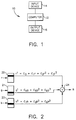
- the present invention is typically implemented in a system 10, as illustrated in Fig. 1, which includes a computer 12 such as one of the computers from the Apple MacIntosh II family.
- the computer 12 typically transforms a color image from an input device 14, such as a Microtek 600ZS scanner, into color variables for a particular output device, such as the color monitor provided with the MacIntosh system designated Apple Color MO401, so that the image captured by the input device 14 is accurately represented on the display of the output device 16.
- Other input devices could be video cameras and photo CDs while other output devices could be printers or specialized monitors.
- R C o + C1r + C2r2 + C3r3 + C4g + C5g2 + C6g3 + C7b + C8b2 + C9b3
- G C10 + C11r + C12r2 + C13r3 + C14g + C15g2 + C16g3 + C17b + C18b2 + C19b3
- B C20 + C21r + C22r2 + C23r3 + C24g + C25g2 + C26g3 + C27b + C28b2 + C29b3
- R, G and B are the red, green and blue color the outputs provided by computer 12 to the output device 16
- r, g and b are the color inputs to the computer 12 from the input device 14
- C0 - C29 are transformation constants which essentially map the colors produced by the input device 14 to the same or closest colors possible by the
- the present invention implements portions or segments of equations 1-3, the single variable segments, using 1D LUTs.
- the segment: C0 + C1r + C2r2 + C3r3 (4) is implemented as a single look-up table, such that for each value of r, when r is used as the index, the output of the table is the precomputed result of equation (4).
- the creation of the contents or entries of the table for equation (4) is easily accomplished by a person of ordinary skill in the art executing equation (4) for each possible value of r and storing the result at location r in the table. For example, at table location nine or T(9) would be stored C0 + C1*9 + C2*92 + C3*93.
- the combining of the different parts or segments of equation (1) into a single output is performed by an addition operation or element as shown in Figure 2 where the outputs of tables 20, 21 and 22 for equation 3 are shown and the final result is produced by the addition or summation element or operation 24.
- All the outputs associated with the transforms of equations (1) - (3) can be produced using one dimensional table look-ups and additions as illustrated in Figure 3.
- the first three tables 30, 32 and 34, are the input shapers.
- the results of the shapers are fed into or used to access the 9 1D LUTs in the middle.
- Red1 implements C o + C1r + C2r2 + C3r3
- Green1 implements C4g + C5g2 + C6g3
- Blue1 implements C7b + C8b2 + C9b3
- Red2 implements C10 + C11r + C12r2 + C13r3
- Green2 implements C14g + C15g2 + C16g3
- Blue2 implements C17b + C18b2 + C19b3
- Red3 implements C20 + C21r + C22r2 + C23r3
- Green3 implements C24g + C25g2 + C26g3 Blue3 implements C27b + C28b2 + C29b3
- a clipping function 48 which keeps the outputs in a desired bit range, can be provided prior to the output shapers 50, 52 and 54 which are also 1D LUTs.
- FIG. 4 A timewise more efficient implementation of equations (1) - (3) is illustrated in Figure 4.
- the tables 60, 61 and 62 are a combination of the corresponding tables Red1 - Blue3, such that only a single index is used to access a table holding all the intermediate values associated with each input variable.
- the index RI' is used to simultaneously obtain the intermediate values R1, R2 and R3 from table 60.
- the tables 60, 61 and 62 are of course three times as wide as the tables of Figure 3.
- Figures 3 and 4 can be implemented using hardwired devices such as ROMs or RAMs and adder circuits.
- the operations of Figures 3 and 4 can be performed by a parallel computer with multiple processors such that a first processor accesses table 60 while two other processors access tables 61 and 62, the first processor could then perform the addition operation 42 while the two other processors perform the additions 44 and 46.
- three different processors could perform the additions 42, 44 and 46 implementing Figures 3 and 4 as pipelines.
- the preferred implementation uses a low cost single computer.
- FIG. 5 One way of performing the operations of Figure 4 in a single computer is illustrated in Figure 5.
- the operation starts with the look-up step 70 for the red input RI, however, starting with the red input look-up is arbitrary and the start could just as well be with the green look-up 72 or the blue look-up 74.
- These steps 70, 72 and 74 perform the operations of tables 30, 32 and 34 of Figure 3.
- the look-up steps 76, 78 and 80 are performed to obtain the intermediate values for each variable in a single access. This corresponds to the tables Red1 - Blue3 of Figure 3 or tables 60, 62 and 64 of Figure 4.
- Each of these steps 76, 78 and 80 can be accomplished with a vector read operation in the preferred C language.
- the addition step 82 performs the addition operations 42, 44 and 46 of Figures 3 and 4 while the look-ups 84, 86 and 88 correspond to 50, 52 and 54 of Figure 3.
- Equation (5) A more complex and more accurate color transformation is represented by equation (5).
- R C0 + C1r + C2r2 + C3r3 + C4g + C5g2 + C6g3 + C7b + C8b2 + C9b3 + C10rg (5)
- rg is a cross term that provides additional compensation to the red output.
- K0(r+g)2 K0r2 + 2K0rg + K0g2 (6)
- K0(r+g)2/2 K0r2/2 + K0rg + K0g2/2 (7).
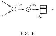
- a single look-up table is used to implement the cross term rg, as illustrated in Figure 6.
- the r and g inputs are added together by adder 100 and then divided by two by a shifter 102 (a simple shift although this isn't really necessary since table 104 could be 511 entries long instead of 256).
- Table 104 implements a square function and multiplies the result by 1/2K0 resulting in 1/2K0(r + g)2 which is 1/2K0r2 + K0rg + 1/2K0g2 the extra 1/2K0r2 + 1/2K0g2 secondary terms are removed or compensated by the single variable term tables.
- - 1/2K0r2 is added to the function used to produce the entries of the single variable red table
- - 1/2K0g2 is added the function used to produce the entries for the single variable green table.
- the steps of creating the tables contents includes a compensation operation.
- the first step is to identify a mathematical equation with the same number of variables as in the cross term and the desired cross term. This equation will probably include secondary single variable terms that do not appear in the transform.
- the equation is then combined with the transform, absent the cross terms, to produce a transform that needs to be corrected or compensated but has the desired cross terms.
- the uncorrected transform is now compensated by subtracting out the secondary single variable terms thereby removing the effect of the secondary unwanted terms.
- the tables are then created by using the single variable terms and the single variable compensation terms to create the single variable table contents and the combined cross term variables to create the cross term table contents. To obtain the complete transform the outputs of the tables just need to be summed.
- Figure 7 is an example of a full transform with the simple cross terms rg, gr and gb.
- the multivariable implemented in tables TR1, TB1, TG1, and TRG1 in Figure 7 is equation (5) while tables TR2, TB2, TG2 and TRG2 implement a corresponding equation for the G input and tables TR3, TG3 and TGB3 implement a corresponding equation for the B input.
- the output of table 110 is applied to tables TR1, TR2 and TR3
- the output of table 112 is applied to tables TG1, TG2 and TG3
- the output of table 114 is applied to tables TB1, TB2 and TB3.
- the output of table 110 is also applied to adders (or adder operations) 116 and 118, while the output of table 112 is also applied to adders 116 and 118 and the output of table 114 is applied to adders 118 and 120.
- the adder outputs are divided (shifted) by shift elements or operations 122, 124 and 126 and applied to tables TRG1, TRG2 and TBG3.
- the outputs of tables TR1, TG1 and TB1 are added to the output of TRG1 by adders or adder operations 128, 130 and 132 and applied to table 134, while corresponding operations are performed by adders 136, 138, 140, 142, 144 and 146 along with tables 148 and 150.
- Table 160 could implement a square function resulting in r2
- table 162 could implement a square function resulting in g2
- adder operation 164 could combine the terms
- table 164 could implement a square function and multiply that by 1/2K0 resulting in 1/2K0(r2 + g2)2 which is 1/2K0r4 + K0r2g2 + 1/2K0g4 the extra 1/2K0r4 + 1/2K0g4 are taken off or compensated for in the tables that implement the single variable terms in a manner as previously described.
- cross terms of all sorts can be added to the basic form to provide more power and flexibility at the tradeoff of increased size and processing time.
- a process can be built by a person of ordinary skill in the art that recognizes the form variant that it is required, so that the extra overhead is only incurred when it is necessary for the more elaborate or precise color transformation.
- the tables are generally 8 bits by 256 entries, their size can be changed in either direction (more bits or more entries) to add more accuracy to the transform.
Landscapes
- Engineering & Computer Science (AREA)
- Physics & Mathematics (AREA)
- General Physics & Mathematics (AREA)
- Data Mining & Analysis (AREA)
- Theoretical Computer Science (AREA)
- Pure & Applied Mathematics (AREA)
- Mathematical Analysis (AREA)
- Mathematical Optimization (AREA)
- Computational Mathematics (AREA)
- Mathematical Physics (AREA)
- Algebra (AREA)
- Software Systems (AREA)
- General Engineering & Computer Science (AREA)
- Databases & Information Systems (AREA)
- Multimedia (AREA)
- Signal Processing (AREA)
- Color Image Communication Systems (AREA)
- Image Processing (AREA)
- Compression Of Band Width Or Redundancy In Fax (AREA)
Applications Claiming Priority (2)
| Application Number | Priority Date | Filing Date | Title |
|---|---|---|---|
| US95673292A | 1992-10-06 | 1992-10-06 | |
| US956732 | 1992-10-06 |
Publications (1)
| Publication Number | Publication Date |
|---|---|
| EP0591931A1 true EP0591931A1 (fr) | 1994-04-13 |
Family
ID=25498625
Family Applications (1)
| Application Number | Title | Priority Date | Filing Date |
|---|---|---|---|
| EP93116093A Withdrawn EP0591931A1 (fr) | 1992-10-06 | 1993-10-05 | Procédé et appareil pour coder et exécuter des transformations multivariables de couleur |
Country Status (2)
| Country | Link |
|---|---|
| EP (1) | EP0591931A1 (fr) |
| JP (1) | JPH06223167A (fr) |
Citations (3)
| Publication number | Priority date | Publication date | Assignee | Title |
|---|---|---|---|---|
| EP0084228A2 (fr) * | 1981-12-07 | 1983-07-27 | Xerox Corporation | Modification numérique de couleurs |
| EP0272655A2 (fr) * | 1986-12-23 | 1988-06-29 | Dainippon Screen Mfg., Co., Ltd. | Procédé et appareil de génération de données d'une table de consultation |
| US5075767A (en) * | 1987-06-05 | 1991-12-24 | Canon Kabushiki Kaisha | Digital color image signal processing apparatus |
-
1993
- 1993-10-04 JP JP5247739A patent/JPH06223167A/ja active Pending
- 1993-10-05 EP EP93116093A patent/EP0591931A1/fr not_active Withdrawn
Patent Citations (3)
| Publication number | Priority date | Publication date | Assignee | Title |
|---|---|---|---|---|
| EP0084228A2 (fr) * | 1981-12-07 | 1983-07-27 | Xerox Corporation | Modification numérique de couleurs |
| EP0272655A2 (fr) * | 1986-12-23 | 1988-06-29 | Dainippon Screen Mfg., Co., Ltd. | Procédé et appareil de génération de données d'une table de consultation |
| US5075767A (en) * | 1987-06-05 | 1991-12-24 | Canon Kabushiki Kaisha | Digital color image signal processing apparatus |
Also Published As
| Publication number | Publication date |
|---|---|
| JPH06223167A (ja) | 1994-08-12 |
Similar Documents
| Publication | Publication Date | Title |
|---|---|---|
| US5793885A (en) | Computationally efficient low-artifact system for spatially filtering digital color images | |
| US4511989A (en) | Linear interpolating method and color conversion apparatus using this method | |
| US5278640A (en) | Color modification utilizing two coefficients | |
| US5678033A (en) | Multi-stage interpolation processor | |
| US6758574B1 (en) | Conversions between standard color spaces | |
| US7177469B2 (en) | Color conversion device and color conversion method | |
| US20030231794A1 (en) | Optimising processing gamuts for colour conversion chains | |
| US6052703A (en) | Method and apparatus for determining discrete cosine transforms using matrix multiplication and modified booth encoding | |
| US6275605B1 (en) | Method for adjusting the tone scale of a digital image | |
| US5689592A (en) | Parallel processing of digital signals in a single arithmetic/logic unit | |
| US5432892A (en) | Volummetric linear interpolation | |
| US8947599B2 (en) | Method and apparatus for adjusting chroma and luma for a video signal | |
| ATE4525T1 (de) | Korrekturschaltung zur verbesserung der konturenschaerfe von fernsehbildern. | |
| US4785412A (en) | Double precision approximate quotient network | |
| Kanamori et al. | Novel color transformation algorithm and its applications | |
| JP2938115B2 (ja) | 色信号変換回路 | |
| JPH05120416A (ja) | 色変換装置 | |
| US5847980A (en) | Product-summing arithmetic circuit | |
| US5828816A (en) | Image processing apparatus and image processing method | |
| US6028590A (en) | Color conversion for processors | |
| JPH06223167A (ja) | カラー多変数変換の符号化および実行のための方法および装置 | |
| JP3576612B2 (ja) | 色変換処理装置 | |
| US5831687A (en) | Color video signal processing method and apparatus for converting digital color difference component signals into digital RGB component signals by a digital conversion | |
| JPH05284346A (ja) | 色変換装置 | |
| JP3364813B2 (ja) | 色逆変換処理装置及び映像信号処理装置 |
Legal Events
| Date | Code | Title | Description |
|---|---|---|---|
| PUAI | Public reference made under article 153(3) epc to a published international application that has entered the european phase |
Free format text: ORIGINAL CODE: 0009012 |
|
| AK | Designated contracting states |
Kind code of ref document: A1 Designated state(s): DE FR GB |
|
| 17P | Request for examination filed |
Effective date: 19940920 |
|
| STAA | Information on the status of an ep patent application or granted ep patent |
Free format text: STATUS: THE APPLICATION HAS BEEN WITHDRAWN |
|
| 18W | Application withdrawn |
Withdrawal date: 19950630 |