EP0591932B1 - Stuhl, insbesondere Büro- oder Arbeitsstuhl - Google Patents
Stuhl, insbesondere Büro- oder Arbeitsstuhl Download PDFInfo
- Publication number
- EP0591932B1 EP0591932B1 EP93116099A EP93116099A EP0591932B1 EP 0591932 B1 EP0591932 B1 EP 0591932B1 EP 93116099 A EP93116099 A EP 93116099A EP 93116099 A EP93116099 A EP 93116099A EP 0591932 B1 EP0591932 B1 EP 0591932B1
- Authority
- EP
- European Patent Office
- Prior art keywords
- seat
- carrier
- chair
- joint
- seat part
- Prior art date
- Legal status (The legal status is an assumption and is not a legal conclusion. Google has not performed a legal analysis and makes no representation as to the accuracy of the status listed.)
- Expired - Lifetime
Links
- 230000033001 locomotion Effects 0.000 claims abstract description 10
- 210000000629 knee joint Anatomy 0.000 claims abstract description 4
- 230000007246 mechanism Effects 0.000 abstract description 4
- 210000003127 knee Anatomy 0.000 description 2
- 230000001360 synchronised effect Effects 0.000 description 2
- 230000001154 acute effect Effects 0.000 description 1
- 230000005540 biological transmission Effects 0.000 description 1
Images
Classifications
-
- A—HUMAN NECESSITIES
- A47—FURNITURE; DOMESTIC ARTICLES OR APPLIANCES; COFFEE MILLS; SPICE MILLS; SUCTION CLEANERS IN GENERAL
- A47C—CHAIRS; SOFAS; BEDS
- A47C1/00—Chairs adapted for special purposes
- A47C1/02—Reclining or easy chairs
- A47C1/031—Reclining or easy chairs having coupled concurrently adjustable supporting parts
- A47C1/032—Reclining or easy chairs having coupled concurrently adjustable supporting parts the parts being movably-coupled seat and back-rest
- A47C1/03255—Reclining or easy chairs having coupled concurrently adjustable supporting parts the parts being movably-coupled seat and back-rest with a central column, e.g. rocking office chairs
-
- A—HUMAN NECESSITIES
- A47—FURNITURE; DOMESTIC ARTICLES OR APPLIANCES; COFFEE MILLS; SPICE MILLS; SUCTION CLEANERS IN GENERAL
- A47C—CHAIRS; SOFAS; BEDS
- A47C1/00—Chairs adapted for special purposes
- A47C1/02—Reclining or easy chairs
- A47C1/031—Reclining or easy chairs having coupled concurrently adjustable supporting parts
- A47C1/032—Reclining or easy chairs having coupled concurrently adjustable supporting parts the parts being movably-coupled seat and back-rest
- A47C1/03261—Reclining or easy chairs having coupled concurrently adjustable supporting parts the parts being movably-coupled seat and back-rest characterised by elastic means
- A47C1/03272—Reclining or easy chairs having coupled concurrently adjustable supporting parts the parts being movably-coupled seat and back-rest characterised by elastic means with coil springs
Definitions
- the invention relates to a chair, in particular an office or work chair, as specified in the preamble of claim 1.
- a chair is known from DE 40 41 157 A1.
- the backrest is always tilted backwards with a downward movement of the rear area of the seat support is coupled, in a chair of the type mentioned the entire seat part is raised when the backrest is tilted backwards.
- This has the advantage that the restoring force for returning the backrest into the upright position is applied directly by the weight of the person sitting on the seat part. It is therefore not necessary to use this restoring force through energy stores such as gas springs or the like. which must be adjusted to the weight of a user.
- a disadvantage of the known chair is that the lifting of the seat part when the backrest is tilted backwards is unusual and even uncomfortable for the user, in particular because it is associated with a shift in the seat pressure in the direction of the front edge of the seat, to the extreme case that the contact of the feet with the floor is lost due to the upward movement of the front part of the seat.
- the invention has for its object to design a chair of the type mentioned with structurally simple means so that the desired upward movement of the seat part for generating the counterforce to the backward inclination of the backrest is such that it is ergonomically advantageous and is not perceived by the user as uncomfortable .
- the trajectory of the four-bar transmission guiding the seat part which can be influenced by the choice of the lengths and joint distances of the handlebars is designed in accordance with the invention in such a way that there is a combined pivoting and translational movement of the seat part which corresponds to a pivoting about an imaginary axis which is in front of the front edge of the seat part and so that it runs in the area of the knee joint axis of a seated person. This ensures that the contact between feet and floor remains almost constant over the entire range of motion and the above-mentioned disadvantageous shifting of the seat pressure into the back of the knee does not take place.
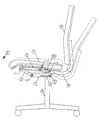
- the chair shown has a base frame 6, to which a seat support 1 is preferably attached in a rotatable and height-adjustable manner.
- a seat support 1 On the seat support 1, the approximately horizontally extending arm of the backrest support 4 is mounted in a horizontal-axis swivel joint D, which carries the backrest 8 with its other, upward-pointing arm.
- a section of the back support 4, which is extended towards the front via the swivel joint D, is articulated in a connecting joint C to the seat part 3, which carries a seat plate with cushion 7.
- the seat part 3 in the joint B is connected to a double joint lever 2 which is articulated in the joint A on the seat support 1.
- An arm 9 of the back support 4 projecting downward from the swivel joint D is supported against the seat support 1 by an energy accumulator 9.
- the section 10 of the back support 4 lying between the swivel joint D and the connecting joint C forms a rear linker, and the double articulated lever 2 forms a front link of a four-link mechanism leading the seat part 3 with the articulation points A, B, C and D.
- the link 10 is from the swivel joint D. from almost horizontally directed towards the front, while the front link 2 also runs forward from the seat support-side joint A and inclines upward at an acute angle.
- the seat support 3 and thus the seat plate 7 is moved upwards when the backrest 8 is tilted back into the dashed position, with a combined translational and rotary movement which corresponds to a pivoting about an imaginary horizontal pivot axis K, which is located at a distance in front of and slightly above the front edge of the seat plate 7, approximately where the knee joint axis of a person of normal size sitting on the seat plate 7 would be.
- the up and down movement of the seat plate 7 associated with the change in inclination of the backrest 8 thus leaves the position of the knees of the user, and thus the contact of the feet with the floor is essentially unaffected.
- the restoring moment counteracting the backward inclination of the backrest 8 is, as mentioned at the outset, applied by the weight of the person sitting on the seat plate 7.
- the energy accumulator 5 does not need to apply this restoring moment, but only serves to hold the chair in a defined position in the unoccupied state.
- conventional locking means acting on the energy accumulator or other parts of the synchronous mechanism can also be provided in order to also rigidly lock the chair in a desired position.
- the drawing shows only the parts that are essential for the kinematics in the drawing plane. It goes without saying that the joints, links, etc. shown are designed or arranged twice so that the seat part and back support are adequately supported over the width of the chair.
Landscapes
- Health & Medical Sciences (AREA)
- Dentistry (AREA)
- General Health & Medical Sciences (AREA)
- Chairs Characterized By Structure (AREA)
- Special Chairs (AREA)
- Chair Legs, Seat Parts, And Backrests (AREA)
- Plural Heterocyclic Compounds (AREA)
- Chairs For Special Purposes, Such As Reclining Chairs (AREA)
Description
- Die Erfindung betrifft einen Stuhl, insbesondere einen Büro- oder Arbeitsstuhl, wie im Oberbegriff des Anspruchs 1 angegeben. Eine derartiger Stuhl ist aus DE 40 41 157 A1 bekannt. Während bei den bis dahin bekannten und üblichen Synchronmechaniken, die in verschiedenen, mehr oder weniger komplizierten Ausführungen bekannt sind (z.B. DE 35 20 188 A1, DE 37 41 472 A1 und EP 0 179 933 A1), die Rückwärtsneigung der Rückenlehne stets mit einer Abwärtsbewegung des hinteren Bereiches des Sitzträgers gekoppelt ist, wird bei einem Stuhl der eingangs genannten Art das gesamte Sitzteil beim Rückwärtsneigen der Rückenlehne angehoben. Dies hat den Vorteil, daß die Rückstellkraft für das Rückstellen der Rückenlehne in die aufrechte Stellung unmittelbar vom Gewicht der auf dem Sitzteil sitzenden Person aufgebracht wird. Es ist daher nicht erforderlich, diese Rückstellkraft durch Kraftspeicher, wie Gasfedern od.dgl. aufzubringen, die auf das Gewicht einer Benutzerperson eingestellt werden müsssen.
- Ein Nachteil des bekannten Stuhls liegt jedoch darin, daß das Anheben des Sitzteils beim Rückwärtsneigen der Rückenlehne für den Benutzer ungewohnt und sogar unbequem ist, und zwar insbesondere deshalb, weil damit eine Verlagerung des Sitzflächendruckes in Richtung auf die Sitzvorderkante verbunden ist, bis zu dem Extremfall, daß durch die Aufwärtsbewegung des vorderen Sitzteilbereiches der Kontakt der Füße zum Boden verloren geht.
- Der Erfindung liegt die Aufgabe zugrunde, einen Stuhl der genannten Art mit konstruktiv einfachen Mitteln so auszugestalten, daß die für die Erzeugung der Gegenkraft zur Rückwärtsneigung der Lehne gewünschte Aufwärtsbewegung des Sitzteils derart verläuft, daß sie ergometrisch vorteilhaft ist und vom Benutzer nicht als unbequem empfunden wird.
- Diese Aufgabe wird erfindungsgemäß mit den im Anspruch 1 angegebenen Merkmalen des Stuhls gelöst. Die Unteransprüche beziehen sich auf vorteilhafte weitere Ausgestaltungen.
- Die durch die Wahl der Längen und Gelenkabstände der Lenker beeinflußbare Bahnkurve des das Sitzteil führenden Viergelenkgetriebes ist erfindungsgemäß derart ausgebildet, daß sich eine kombinierte Schwenk- und Translationsbewegung des Sitzteils ergibt, die einer Schwenkung um eine gedachte Achse entspricht, die vor der Vorderkante des Sitzteils und damit im Bereich der Kniegelenkachse einer sitzenden Person verläuft. Damit wird erreicht, daß der Kontakt zwischen Füßen und Boden über den gesamten Bewegungsbereich nahezu konstant bleibt und die oben erwähnte nachteilige Verlagerung des Sitzflächendruckes in den Kniekehlenbereich hinein nicht stattfindet.
- Eine Ausführungsform der Erfindung wird anhand der Zeichnung näher erläutert. Diese zeigt den Bürostuhl in einer auf die kinematisch wesentlichen Teile reduzierten schematischen Seitenansicht.
- Der dargestellte Stuhl hat ein Fußgestell 6, an dem vorzugsweise drehbar und höhenverstellbar ein Sitzträger 1 befestigt ist. An dem Sitzträger 1 ist in einem horizontalachsigen Drehgelenk D der ungefähr horizontal verlaufende Arm des Rückenlehnenträgers 4 gelagert, der mit seinem anderen, nach oben gerichteten Arm die Rückenlehne 8 trägt. Ein über das Drehgelenk D nach vorne verlängerter Abschnitt des Rückenträgers 4 ist in einem Verbindungsgelenk C mit dem Sitzteil 3 gelenkig verbunden, welches eine Sitzplatte mit Polster 7 trägt. Im vorderen Bereich ist der Sitzteil 3 im Gelenk B mit einem Doppelgelenkhebel 2 verbunden, der im Gelenk A am Sitzträger 1 angelenkt ist. Ein vom Drehgelenk D nach unten ragender Arm 9 des Rückenträgers 4 ist durch einen Kraftspeicher 9 gegen den Sitzträger 1 abgestützt.
- Der zwischen Drehgelenk D und Verbindungsgelenk C liegende Abschnitt 10 des Rückenträgers 4 bildet einen hinteren Lener, und der Doppelgelenkhebel 2 bildet einen vorderen Lenker eines den Sitzteil 3 führenden Viergelenkgetriebes mit den Gelenkpunkten A, B, C und D. Der Lenker 10 ist vom Drehgelenk D aus nahezu horizontal nach vorne gerichtet, während der vordere Lenker 2 vom sitzträgerseitigen Gelenk A aus ebenfalls nach vorne und in einem spitzen Winkel nach oben geneigt verläuft. Aufgrund der gewählten Geometrie des Viergelenkgetriebes wird der Sitzträger 3 und damit die Sitzplatte 7 beim Rückwärtsneigen der Rückenlehne 8 in die gestrichelte Position nach oben bewegt, und zwar mit einer kombinierten Translations- und Drehbewegung, die einer Schwenkung um einer gedachte horizontale Schwenkachse K entspricht, die in einem Abstand vor und etwas oberhalb der Vorderkante der Sitzplatte 7 liegt, und zwar etwa dort, wo sich die Kniegelenkachse einer auf der Sitzplatte 7 sitzenden Person normaler Größe befinden würde. Die mit der Neigungsänderung der Rückenlehne 8 verbundene Auf- und Abbewegung der Sitzplatte 7 läßt somit die Lage der Knie des Benutzers, und damit auch den Kontakt der Füße zum Boden im wesentlichen unbeeinflußt.
- Das der Rückwärtsneigung der Lehne 8 entgegenwirkende Rückstellmoment wird, wie eingangs erwähnt, vom Gewicht der auf der Sitzplatte 7 sitzenden Person aufgebracht. Der Kraftspeicher 5 braucht dieses Rückstellmoment nicht aufzubringen, sondern dient nur dazu, den Stuhl im unbesessenen Zustand in einer definierten Position zu halten. Selbstverständlich können übliche, auf den Kraftspeicher oder andere Teile der Synchronmechanik wirkende Arretiermittel vorgesehen sind, um den Stuhl in einer gewünschten Position auch starr zu arretieren.
- Wie bereits erwähnt, zeigt die Zeichnung vereinfacht nur die für die Kinematik in der Zeichenebene wesentlichen Teile. Es ist selbstverständlich, daß die dargestellten Gelenke, Lenker usw. so ausgestaltet oder doppelt angeordnet sind, daß Sitzteil und Rückenträger über die Breite des Stuhls ausreichend abgestützt sind.
Claims (4)
- Stuhl, insbesondere Büro- oder Arbeitsstuhl, mit einem Sitzträger (1), einem daran in einem Drehgelenk (D) schwenkbar gelagerten Rückenträger (4) und einem Sitzteil (3, 7), das in seinem vorderen Bereich über einen Doppelgelenkhebel (2) mit dem Sitzträger (1) verbunden ist und in einem dahinter liegenden Verbindungsgelenk (C) mit dem Rückenträger (4) verbunden ist, wobei der Doppelgelenkhebel (2) einen vorderen Lenker und der zwischen Drehgelenk (D) und Verbindungsgelenk (C) liegende Teil (10) des Rückenträgers (4) einen hinteren Lenker eines das Sitzteil (3, 7) führenden Viergelenkgetriebes bilden, das bei Rückwärtsneigung des Rückenträgers (4) ein Anheben des Sitzteils (3, 7) relativ zum Sitzträger (1) bewirkt,
dadurch gekennzeichnet, daß die Längen des vorderen Lenkers (2) und hinteren Lenkers (10) und die Position ihrer Gelenkpunkte (A, B, C, D) so gewählt sind, daß die von ihnen gesteuerte Bewegung des Sitzträgers (3, 7) annähernd eine Schwenkbewegung um eine gedachte, im Abstand vor der Vorderkante des Sitzteils (3, 7) liegende horizontale Schwenkachse (K) ist. - Stuhl nach Anspruch 1, dadurch gekennzeichnet, daß die gedachte Schwenkachse (K) etwa mit der Kniegelenkachse einer auf dem Sitzteil (3, 7) sitzenden Person zusammenfällt.
- Stuhl nach Anspruch 1 oder 2 , dadurch gekennzeichnet, daß der Rückenträger (4) einen unter das Sitzteil (3, 7) greifenden, ungefähr horizontalen Arm aufweist, der am Sitzträger (1) im Drehgelenk (D) gelagert ist und dessen über das Drehgelenk (D) hinaus nach vorne verlängerter Abschnitt (10) den mit dem Sitzteil im Verbindungsgelenk (C) verbundenen hinteren Lenker bildet.
- Stuhl nach einem der Ansprüche 1 bis 3 , dadurch gekennzeichnet, daß ein am Rückenträger (4) oder am Sitzträger (3, 7) oder einem der Lenker (2, 10) angreifender Kraftspeicher (5) vorgesehen ist, der den unbesessenen Stuhl in definierter Lage hält.
Applications Claiming Priority (2)
| Application Number | Priority Date | Filing Date | Title |
|---|---|---|---|
| DE4233628 | 1992-10-06 | ||
| DE4233628A DE4233628A1 (de) | 1992-10-06 | 1992-10-06 | Stuhl, insbesondere Büro- oder Arbeitsstuhl |
Publications (2)
| Publication Number | Publication Date |
|---|---|
| EP0591932A1 EP0591932A1 (de) | 1994-04-13 |
| EP0591932B1 true EP0591932B1 (de) | 1995-12-20 |
Family
ID=6469786
Family Applications (1)
| Application Number | Title | Priority Date | Filing Date |
|---|---|---|---|
| EP93116099A Expired - Lifetime EP0591932B1 (de) | 1992-10-06 | 1993-10-05 | Stuhl, insbesondere Büro- oder Arbeitsstuhl |
Country Status (5)
| Country | Link |
|---|---|
| EP (1) | EP0591932B1 (de) |
| AT (1) | ATE131701T1 (de) |
| DE (2) | DE4233628A1 (de) |
| ES (1) | ES2052470T3 (de) |
| GR (1) | GR940300043T1 (de) |
Cited By (3)
| Publication number | Priority date | Publication date | Assignee | Title |
|---|---|---|---|---|
| US6637072B2 (en) | 2000-09-29 | 2003-10-28 | Formway Furniture Limited | Castored base for an office chair |
| US7441839B2 (en) | 2000-09-28 | 2008-10-28 | Formway Furniture Limited | Reclinable chair |
| US11553797B2 (en) | 2015-04-13 | 2023-01-17 | Steelcase Inc. | Seating arrangement |
Families Citing this family (9)
| Publication number | Priority date | Publication date | Assignee | Title |
|---|---|---|---|---|
| NZ518944A (en) | 2002-05-14 | 2004-09-24 | Formway Furniture Ltd | Height adjustable arm for chair with outer stem releasably lockable to inner stem by engagement of recesses |
| WO2009134451A1 (en) * | 2008-05-02 | 2009-11-05 | Haworth, Inc. | Tension mechanism for a weight-responsive chair |
| CN203952966U (zh) * | 2014-06-26 | 2014-11-26 | 陈国巨 | 椅背后仰时坐垫前移并同时下降的椅子 |
| JP6826043B2 (ja) | 2015-04-13 | 2021-02-03 | スティールケース インコーポレイテッド | 着座用構成体 |
| US10966527B2 (en) | 2017-06-09 | 2021-04-06 | Steelcase Inc. | Seating arrangement and method of construction |
| US11259637B2 (en) | 2015-04-13 | 2022-03-01 | Steelcase Inc. | Seating arrangement |
| CN113925304B (zh) | 2016-02-05 | 2024-09-13 | 佛姆维家具有限公司 | 椅子和部件 |
| AU2020224628B2 (en) | 2019-02-21 | 2025-04-24 | Steelcase Inc. | Body support assembly and methods for the use and assembly thereof |
| US11357329B2 (en) | 2019-12-13 | 2022-06-14 | Steelcase Inc. | Body support assembly and methods for the use and assembly thereof |
Family Cites Families (3)
| Publication number | Priority date | Publication date | Assignee | Title |
|---|---|---|---|---|
| DE3617624A1 (de) * | 1986-05-26 | 1987-12-03 | Drabert Soehne | Stuhl |
| US4834454A (en) * | 1987-05-15 | 1989-05-30 | Faultless-Doerner Manufacturing Inc. | Office chair with tiltable seat and back |
| CA2087981A1 (en) * | 1991-05-24 | 1992-11-25 | Peter Tobler | Work chair, more particularly an office chair |
-
1992
- 1992-10-06 DE DE4233628A patent/DE4233628A1/de not_active Withdrawn
-
1993
- 1993-10-05 DE DE59301201T patent/DE59301201D1/de not_active Expired - Fee Related
- 1993-10-05 EP EP93116099A patent/EP0591932B1/de not_active Expired - Lifetime
- 1993-10-05 ES ES93116099T patent/ES2052470T3/es not_active Expired - Lifetime
- 1993-10-05 AT AT93116099T patent/ATE131701T1/de not_active IP Right Cessation
-
1994
- 1994-07-29 GR GR940300043T patent/GR940300043T1/el unknown
Cited By (4)
| Publication number | Priority date | Publication date | Assignee | Title |
|---|---|---|---|---|
| US7441839B2 (en) | 2000-09-28 | 2008-10-28 | Formway Furniture Limited | Reclinable chair |
| US7798573B2 (en) | 2000-09-28 | 2010-09-21 | Formway Furniture Limited | Reclinable chair |
| US6637072B2 (en) | 2000-09-29 | 2003-10-28 | Formway Furniture Limited | Castored base for an office chair |
| US11553797B2 (en) | 2015-04-13 | 2023-01-17 | Steelcase Inc. | Seating arrangement |
Also Published As
| Publication number | Publication date |
|---|---|
| ES2052470T3 (es) | 1996-04-16 |
| ES2052470T1 (es) | 1994-07-16 |
| DE4233628A1 (de) | 1994-04-07 |
| GR940300043T1 (en) | 1994-07-29 |
| ATE131701T1 (de) | 1996-01-15 |
| DE59301201D1 (de) | 1996-02-01 |
| EP0591932A1 (de) | 1994-04-13 |
Similar Documents
| Publication | Publication Date | Title |
|---|---|---|
| EP1256293B1 (de) | Stuhl, insbesondere Bürostuhl | |
| DE3632131C2 (de) | Funktions-Sitzmöbel | |
| EP1911371B1 (de) | Sitzmöbel, insbesondere Bürostuhl | |
| DE102008063617B4 (de) | Fahrzeugsitz | |
| DE102008063616B4 (de) | Fahrzeugsitz | |
| EP0343450B1 (de) | Stuhl, insbesondere Arbeits- oder Bürostuhl | |
| DE3428960C2 (de) | ||
| DE10122948C1 (de) | Stuhl, insbesondere Bürostuhl | |
| EP1906792B1 (de) | Stuhl, insbesondere bürostuhl | |
| DE102008004232B3 (de) | Sitzanordnung mit zwei Fahrzeugsitzen in einer Sitzreihe | |
| EP1301106A1 (de) | Stuhl | |
| DE202007018357U1 (de) | Stuhl | |
| EP0591932A1 (de) | Stuhl, insbesondere Büro- oder Arbeitsstuhl | |
| DE102011113789B4 (de) | Fahrzeugsitz, insbesondere Kraftfahrzeugsitz | |
| DE29910620U1 (de) | Stuhl, insbesondere Bürostuhl | |
| DE202006005645U1 (de) | Stuhl, insbesondere Bürostuhl | |
| EP1048509A2 (de) | Kraftfahrzeugsitz | |
| DE4219599A1 (de) | Synchronverstelleinrichtung für Bürostühle oder dergleichen | |
| EP1652505B1 (de) | Behandlungsstuhl, insbesondere dentalmedizinischer Behandlungsstuhl | |
| DE19921153A1 (de) | Synchronmechanik für eine korrelierte Sitz-Rückenlehnen-Bewegung eines Bürostuhles | |
| DE2601691A1 (de) | Hebelverstellgetriebe fuer sitz- und liegesessel | |
| DE2450146A1 (de) | Lehn- oder fernsehstuhl mit aufrichtbarer kopfstuetze und beschlag hierfuer | |
| DE102005003383B3 (de) | Synchronmechanik | |
| WO2007012391A1 (de) | Stuhl, insbesondere bürostuhl | |
| DE102010046994B4 (de) | Synchronmechanik |
Legal Events
| Date | Code | Title | Description |
|---|---|---|---|
| PUAI | Public reference made under article 153(3) epc to a published international application that has entered the european phase |
Free format text: ORIGINAL CODE: 0009012 |
|
| AK | Designated contracting states |
Kind code of ref document: A1 Designated state(s): AT BE CH DE DK ES FR GB GR IE IT LI LU MC NL PT SE |
|
| GBC | Gb: translation of claims filed (gb section 78(7)/1977) | ||
| EL | Fr: translation of claims filed | ||
| IECL | Ie: translation for ep claims filed | ||
| ITCL | It: translation for ep claims filed |
Representative=s name: UFFICIO TECNICO ING. A. MANNUCCI |
|
| 17P | Request for examination filed |
Effective date: 19940608 |
|
| TCNL | Nl: translation of patent claims filed | ||
| 17Q | First examination report despatched |
Effective date: 19950524 |
|
| GRAA | (expected) grant |
Free format text: ORIGINAL CODE: 0009210 |
|
| AK | Designated contracting states |
Kind code of ref document: B1 Designated state(s): AT BE CH DE DK ES FR GB GR IE IT LI LU MC NL PT SE |
|
| PG25 | Lapsed in a contracting state [announced via postgrant information from national office to epo] |
Ref country code: MC Free format text: LAPSE BECAUSE OF NON-PAYMENT OF DUE FEES Effective date: 19951220 Ref country code: GR Free format text: LAPSE BECAUSE OF FAILURE TO SUBMIT A TRANSLATION OF THE DESCRIPTION OR TO PAY THE FEE WITHIN THE PRESCRIBED TIME-LIMIT Effective date: 19951220 Ref country code: DK Effective date: 19951220 |
|
| REF | Corresponds to: |
Ref document number: 131701 Country of ref document: AT Date of ref document: 19960115 Kind code of ref document: T |
|
| REG | Reference to a national code |
Ref country code: IE Ref legal event code: FG4D Free format text: 66621 |
|
| REF | Corresponds to: |
Ref document number: 59301201 Country of ref document: DE Date of ref document: 19960201 |
|
| ITF | It: translation for a ep patent filed | ||
| PG25 | Lapsed in a contracting state [announced via postgrant information from national office to epo] |
Ref country code: SE Effective date: 19960320 |
|
| REG | Reference to a national code |
Ref country code: ES Ref legal event code: FG2A Ref document number: 2052470 Country of ref document: ES Kind code of ref document: T3 |
|
| ET | Fr: translation filed | ||
| GBT | Gb: translation of ep patent filed (gb section 77(6)(a)/1977) |
Effective date: 19960327 |
|
| SC4A | Pt: translation is available |
Free format text: 960221 AVAILABILITY OF NATIONAL TRANSLATION |
|
| PLBE | No opposition filed within time limit |
Free format text: ORIGINAL CODE: 0009261 |
|
| STAA | Information on the status of an ep patent application or granted ep patent |
Free format text: STATUS: NO OPPOSITION FILED WITHIN TIME LIMIT |
|
| PG25 | Lapsed in a contracting state [announced via postgrant information from national office to epo] |
Ref country code: LU Free format text: LAPSE BECAUSE OF NON-PAYMENT OF DUE FEES Effective date: 19961031 |
|
| 26N | No opposition filed | ||
| REG | Reference to a national code |
Ref country code: GB Ref legal event code: IF02 |
|
| PGFP | Annual fee paid to national office [announced via postgrant information from national office to epo] |
Ref country code: GB Payment date: 20030911 Year of fee payment: 11 |
|
| PGFP | Annual fee paid to national office [announced via postgrant information from national office to epo] |
Ref country code: PT Payment date: 20030924 Year of fee payment: 11 |
|
| PGFP | Annual fee paid to national office [announced via postgrant information from national office to epo] |
Ref country code: NL Payment date: 20031020 Year of fee payment: 11 |
|
| PGFP | Annual fee paid to national office [announced via postgrant information from national office to epo] |
Ref country code: FR Payment date: 20031021 Year of fee payment: 11 |
|
| PGFP | Annual fee paid to national office [announced via postgrant information from national office to epo] |
Ref country code: BE Payment date: 20031024 Year of fee payment: 11 Ref country code: AT Payment date: 20031024 Year of fee payment: 11 |
|
| PGFP | Annual fee paid to national office [announced via postgrant information from national office to epo] |
Ref country code: CH Payment date: 20031027 Year of fee payment: 11 |
|
| PGFP | Annual fee paid to national office [announced via postgrant information from national office to epo] |
Ref country code: IE Payment date: 20031029 Year of fee payment: 11 Ref country code: ES Payment date: 20031029 Year of fee payment: 11 |
|
| PGFP | Annual fee paid to national office [announced via postgrant information from national office to epo] |
Ref country code: DE Payment date: 20031219 Year of fee payment: 11 |
|
| PG25 | Lapsed in a contracting state [announced via postgrant information from national office to epo] |
Ref country code: IE Free format text: LAPSE BECAUSE OF NON-PAYMENT OF DUE FEES Effective date: 20041005 Ref country code: GB Free format text: LAPSE BECAUSE OF NON-PAYMENT OF DUE FEES Effective date: 20041005 Ref country code: AT Free format text: LAPSE BECAUSE OF NON-PAYMENT OF DUE FEES Effective date: 20041005 |
|
| PG25 | Lapsed in a contracting state [announced via postgrant information from national office to epo] |
Ref country code: ES Free format text: LAPSE BECAUSE OF NON-PAYMENT OF DUE FEES Effective date: 20041006 |
|
| PG25 | Lapsed in a contracting state [announced via postgrant information from national office to epo] |
Ref country code: LI Free format text: LAPSE BECAUSE OF NON-PAYMENT OF DUE FEES Effective date: 20041031 Ref country code: CH Free format text: LAPSE BECAUSE OF NON-PAYMENT OF DUE FEES Effective date: 20041031 Ref country code: BE Free format text: LAPSE BECAUSE OF NON-PAYMENT OF DUE FEES Effective date: 20041031 |
|
| PG25 | Lapsed in a contracting state [announced via postgrant information from national office to epo] |
Ref country code: PT Free format text: LAPSE BECAUSE OF NON-PAYMENT OF DUE FEES Effective date: 20050405 |
|
| BERE | Be: lapsed |
Owner name: *COMFORTO G.M.B.H. Effective date: 20041031 |
|
| PG25 | Lapsed in a contracting state [announced via postgrant information from national office to epo] |
Ref country code: NL Free format text: LAPSE BECAUSE OF NON-PAYMENT OF DUE FEES Effective date: 20050501 |
|
| PG25 | Lapsed in a contracting state [announced via postgrant information from national office to epo] |
Ref country code: DE Free format text: LAPSE BECAUSE OF NON-PAYMENT OF DUE FEES Effective date: 20050503 |
|
| GBPC | Gb: european patent ceased through non-payment of renewal fee |
Effective date: 20041005 |
|
| REG | Reference to a national code |
Ref country code: CH Ref legal event code: PL |
|
| REG | Reference to a national code |
Ref country code: IE Ref legal event code: MM4A |
|
| PG25 | Lapsed in a contracting state [announced via postgrant information from national office to epo] |
Ref country code: FR Free format text: LAPSE BECAUSE OF NON-PAYMENT OF DUE FEES Effective date: 20050630 |
|
| REG | Reference to a national code |
Ref country code: PT Ref legal event code: MM4A Free format text: LAPSE DUE TO NON-PAYMENT OF FEES Effective date: 20050405 |
|
| NLV4 | Nl: lapsed or anulled due to non-payment of the annual fee |
Effective date: 20050501 |
|
| REG | Reference to a national code |
Ref country code: FR Ref legal event code: ST |
|
| PG25 | Lapsed in a contracting state [announced via postgrant information from national office to epo] |
Ref country code: IT Free format text: LAPSE BECAUSE OF NON-PAYMENT OF DUE FEES Effective date: 20051005 |
|
| REG | Reference to a national code |
Ref country code: ES Ref legal event code: FD2A Effective date: 20041006 |
|
| BERE | Be: lapsed |
Owner name: *COMFORTO G.M.B.H. Effective date: 20041031 |