EP0591990A2 - Everting forceps with locking mechanism - Google Patents
Everting forceps with locking mechanism Download PDFInfo
- Publication number
- EP0591990A2 EP0591990A2 EP93116332A EP93116332A EP0591990A2 EP 0591990 A2 EP0591990 A2 EP 0591990A2 EP 93116332 A EP93116332 A EP 93116332A EP 93116332 A EP93116332 A EP 93116332A EP 0591990 A2 EP0591990 A2 EP 0591990A2
- Authority
- EP
- European Patent Office
- Prior art keywords
- leg
- forceps
- legs
- interlocking means
- handle
- Prior art date
- Legal status (The legal status is an assumption and is not a legal conclusion. Google has not performed a legal analysis and makes no representation as to the accuracy of the status listed.)
- Ceased
Links
Images


Classifications
-
- A—HUMAN NECESSITIES
- A61—MEDICAL OR VETERINARY SCIENCE; HYGIENE
- A61B—DIAGNOSIS; SURGERY; IDENTIFICATION
- A61B17/00—Surgical instruments, devices or methods
- A61B17/30—Surgical pincettes, i.e. surgical tweezers without pivotal connections
-
- A—HUMAN NECESSITIES
- A61—MEDICAL OR VETERINARY SCIENCE; HYGIENE
- A61B—DIAGNOSIS; SURGERY; IDENTIFICATION
- A61B17/00—Surgical instruments, devices or methods
- A61B17/28—Surgical forceps
- A61B17/2812—Surgical forceps with a single pivotal connection
- A61B17/2833—Locking means
Definitions
- This invention relates to the field of surgery and more particularly to a tool useful for performing anastomoses and having a locking mechanism.
- anastomosis covers a variety of procedures in which blood vessels or other tubular members, such as parts of the colon, are joined or reconnected. Vessels may be joined in a variety of relative orientations, including end-to-end and end-to-side. Solid tubular structures such as peripheral nerves can also be joined together, as well as solid structures such as subcutaneous tissue and skin.
- Anastomoses are traditionally performed by joining, clipping or suturing the vessels together at the juncture between them.
- Alternatives to suturing have been developed, in order to prevent thrombosis which tends to occur at the points of penetration of the sutures.
- One such alternative, particularly for larger vessels, involves mechanical connectors such as collars.
- a second alternative to suturing is the use of surgical clips which are applied along the vessel juncture to perform a holding function similar to that of sutures, without penetrating the vessel walls. Two such non-penetrating clips are shown in U.S. Pat. Nos. 4,586,503 and 4,733,660 to Kirsch et al.
- the non-penetrating clips are applied over apposed edges of the vessels, the edges first being everted, or turned outward, to form flanges that are gripped between the jaws of the clips. Eversion not only enables the clip jaws to better grip the vessels, but also insures that only the interior surfaces of the vessels are in contact.
- a blood vessel is everted by rotating the exposed end of the vessel such that the vessel's intima is exposed and is transverse to the longitudinal axis of the vessel.
- this part of the vessel end must be everted and held in close relationship while the final steps of joining the blood vessels are performed.
- surgical clips have proven fast, simple to apply and reliable in their holding ability, has accentuated the need for a tool to assist a surgeon in everting vessels while performing anastomoses.
- Clips are typically applied with a small hand-held tool that enables the surgeon to precisely place the clip over the tissue edges, and then to close the clip, as by applying a squeezing pressure to the tool. It is desirable to enable the same surgeon to perform the required vessel eversion, with his free hand.
- the invention comprises an everting forceps, comprising a pair of outer, resilient legs rigidly interconnected at one end thereof, a third leg intermediate the pair of legs, the outer and intermediate legs having respective tips at their free ends, the tips being provided with respective jaws, and further comprising manipulable means connected to the intermediate leg for enabling one to move the intermediate leg to be moved with respect to one of the outer legs.
- a locking mechanism is provided which enables at least one of the outer legs to be locked relative to the intermediate leg.
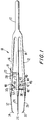
- FIGURE 1 shows an everting forceps 10 embodying the invention.
- the forceps includes three handles 12, 14, 16 of plastic resilient material or spring metal, interconnected in laminar fashion at the proximal end to form a connection head 17.
- the outer handles or legs 12 and 16 are referred to as the lower and upper handles, respectively, according to their position in FIGURE 1, although no particular orientation of the tool is required in use.
- the intermediate handle 14 extends between the lower and upper handles 12 and 16, both of which are bowed outwardly along their unconnected portions, away from the intermediate handle 14.
- the intermediate handle includes a first opening 46 for engaging a locking mechanism 40 and locking the intermediate handle 14 relative to the lower handle 12.
- a second opening 46 is formed in the intermediate handle 14 for receiving a portion of stabilizing member 36.
- the distal end of the intermediate handle 14 includes a leg 24 which tapers towards a tip 26 preferably having, as is shown in the figure, a spherical tip of the type described in U.S. Pat. No. 4,950,281 incorporated herein by reference; although the shape of the tip may be modified as desired for particular applications.
- the upper handle 16 has an aperture 18 near its midpoint, through which a transverse shaft 20 extends.
- the shaft is welded to the intermediate handle 14 and has a button end 22 affixed thereon outside of the upper handle 16.
- the button 22 enables the surgeon to manipulate and position the intermediate handle 14 via movement of upper handle 16, thereby engaging or disengaging the locking mechanism 40, as described hereafter.
- the upper handle 16 also includes an opening 50 having a guide cap 52 for receiving a portion of stabilizing member 36.
- the upper and lower handles 12, 16 have similarly connected legs 28, 32 which are tapered and bent inwardly near their distal ends and terminate at similar jaws 30, 34.
- the legs 28, 32 extend into and are fixedly attached to the respective handles 12, 16.
- each handle and leg could be integral or of one piece construction.
- the jaws 30, 34 face one another opposite the tip 26 of the intermediate leg.
- each jaw is substantially C-shaped, when viewed from the end thereof, and the inner surface 36 of each jaw has a radius of curvature slightly greater than that of the spherical tip 26.
- Each of the jaws may be coated with a plastic material to soften the clamping surfaces.
- the locking mechanism 40 shown in its unengaged position in FIGURE 1, includes a pin 42 mounted to the lower handle 12 and terminating in a triangular engagement tip 43 having a camming surface 44 and a bottom edge 45.
- a disengagement member 48 extends from upper handle 16, has a camming surface 49 for engaging against camming surface 44 of tip 43 forcing tip 43 slightly distally to release it from engagement with the opening 46 of the intermediate handle 14.
- depression of the button 22 causes both the upper handle 16 and the intermediate handle 14 to move together (due to their connection by shaft) in the downward direction towards lower handle 12. Sufficient downward movement causes the engagement tip 43 to extend through the opening 46 in the intermediate handle 14 until the bottom edge 45 rests on the top surface 15 of the intermediate arm 14.
- the forceps 10 of the present invention also include a stabilizing member 36 which extends from the lower handle 12.
- Stabilizing member 36 extends through an opening 46 in the intermediate handle 14 when the locking mechanism is in its engaged position, i.e. when intermediate handle 14 and lower handle 12 are locked in engagement, as shown in FIGURES 2 and 4.
- the stabilizing member 36 further extends through an opening 50 and through guide 52 when the upper handle 16 is depressed, as best shown in FIGURES 3 and 5.
- stabilizing member 36 lists lateral movement of the handles during use.
- the three jaws normally are maintained spaced apart from one another, with the intermediate jaw centered between the arcuate jaws, by the natural resilience of the legs, thus providing a bias against any squeezing action applied by the surgeon.
- the spherical jaw 26 is positioned within the vessel lumen and the lower jaw 30 is positioned against the outside of a vessel. Applying pressure first between the thumb and middle finger tip, the surgeon grasps and partially everts the vessel held between lower jaw 30 and tip 26.
- the lower handle 12 and lower jaw 30 are locked relative to the intermediate handle 14 and tip 26, by depressing the button 22 towards the intermediate handle 14, thereby retaining the first vessel in the jaw and giving the surgeon a free finger and eliminating the necessity caused by having to maintain the first vessel engaged between the lower jaw 30 and intermediate tip 26.
- the jaw 26 is inserted into the lumen of the second vessel, with the jaw 34 on the outside of the second vessel.
- the surgeon grasps the second vessel edge, similarly everting it, and holding the two edges in apposition for convenient application of a clip or other connector. Because the required manipulation is simple, a single surgeon may perform the manipulation of the everting and clipping tools in the process. Once a first suture, staple or clip has been applied, the eversion tends to remain stable, and the forceps 10 can be withdrawn while the remaining clips or sutures are applied. Note that the locking mechanism 40 is released by depressing the handle 16 causing the camming surface 49 to engage along surface 44 of flange 43 until flange 43 drops through opening 46.
- the forceps is not limited to such uses.
- the forceps can be used for effecting skin closures, using sutures or staples to join the approximated edges of the skin. This is particularly relevant in skin closures by staples where assistance ordinarily is necessary to maintain skin eversion, since the instrument eliminates the need for an assistant.
Landscapes
- Health & Medical Sciences (AREA)
- Life Sciences & Earth Sciences (AREA)
- Surgery (AREA)
- Heart & Thoracic Surgery (AREA)
- Engineering & Computer Science (AREA)
- Biomedical Technology (AREA)
- Nuclear Medicine, Radiotherapy & Molecular Imaging (AREA)
- Medical Informatics (AREA)
- Molecular Biology (AREA)
- Animal Behavior & Ethology (AREA)
- General Health & Medical Sciences (AREA)
- Public Health (AREA)
- Veterinary Medicine (AREA)
- Surgical Instruments (AREA)
Abstract
Description
- This invention relates to the field of surgery and more particularly to a tool useful for performing anastomoses and having a locking mechanism.
- The term "anastomosis" covers a variety of procedures in which blood vessels or other tubular members, such as parts of the colon, are joined or reconnected. Vessels may be joined in a variety of relative orientations, including end-to-end and end-to-side. Solid tubular structures such as peripheral nerves can also be joined together, as well as solid structures such as subcutaneous tissue and skin.
- Anastomoses are traditionally performed by joining, clipping or suturing the vessels together at the juncture between them. Alternatives to suturing have been developed, in order to prevent thrombosis which tends to occur at the points of penetration of the sutures. One such alternative, particularly for larger vessels, involves mechanical connectors such as collars. A second alternative to suturing is the use of surgical clips which are applied along the vessel juncture to perform a holding function similar to that of sutures, without penetrating the vessel walls. Two such non-penetrating clips are shown in U.S. Pat. Nos. 4,586,503 and 4,733,660 to Kirsch et al. As described in the former patent, the non-penetrating clips are applied over apposed edges of the vessels, the edges first being everted, or turned outward, to form flanges that are gripped between the jaws of the clips. Eversion not only enables the clip jaws to better grip the vessels, but also insures that only the interior surfaces of the vessels are in contact.
- The use of such non-penetrating clips requires that the vessel or tissue edges be accurately and symmetrically everted. Correct eversion is critical at the beginning of anastomoses and at difficult sites, such as at the heel and toe of an end-to-side anastomosis.
- For an astomosis, a blood vessel is everted by rotating the exposed end of the vessel such that the vessel's intima is exposed and is transverse to the longitudinal axis of the vessel. During anastomosis, this part of the vessel end must be everted and held in close relationship while the final steps of joining the blood vessels are performed. The fact that surgical clips have proven fast, simple to apply and reliable in their holding ability, has accentuated the need for a tool to assist a surgeon in everting vessels while performing anastomoses.
- Clips are typically applied with a small hand-held tool that enables the surgeon to precisely place the clip over the tissue edges, and then to close the clip, as by applying a squeezing pressure to the tool. It is desirable to enable the same surgeon to perform the required vessel eversion, with his free hand.
- One example of a prior art everting forcep is disclosed in U.S. Patent No. 4,950,281 to Kirsch et al., the contents of which are hereby incorporated by reference, where the forceps include a pair of outer legs and an inner leg all cooperating jaws are mounted at the ends of the respective relatively movable legs. The outer legs can be independently manipulated to evert a vessel for anastomosis procedure.
- It would be desirable to provide a mechanism in the everting forceps which could lock one of the legs during manipulation of the other leg. This would advantageously allow the surgeon to release his grip on the locked legs to evert the other vessel with the unlocked leg. The forceps is used by grabbing the vessel between one outer leg and the intermediate leg and everting the vessel. The user maintains pressure on these two legs while the opposing vessel is grabbed and everted by the second free outer leg in cooperation with the intermediate leg.
- In view of the foregoing, the invention comprises an everting forceps, comprising a pair of outer, resilient legs rigidly interconnected at one end thereof, a third leg intermediate the pair of legs, the outer and intermediate legs having respective tips at their free ends, the tips being provided with respective jaws, and further comprising manipulable means connected to the intermediate leg for enabling one to move the intermediate leg to be moved with respect to one of the outer legs. A locking mechanism is provided which enables at least one of the outer legs to be locked relative to the intermediate leg.
- The present invention will be more fully appreciated as the same becomes better understood from the following detailed description of the present invention when considered in connection with the following drawings in which:
- FIGURE 1 is a side view of a tool of the present invention shown in an open position;
- FIGURE 2 is a side view of the tool of the present invention shown with one leg engaged by the locking mechanism;
- FIGURE 3 is a side view of the tool of the present invention shown in a locked and fully closed position;
- FIGURE 4 shows a detailed side view of the locking mechanism of the present invention shown in a locked position; and
- FIGURE 5 shows a detailed side view of the locking mechanism of the present invention shown partially unlocked.
- FIGURE 1 shows an
everting forceps 10 embodying the invention. The forceps includes threehandles connection head 17. For convenience, the outer handles orlegs - The
intermediate handle 14 extends between the lower andupper handles intermediate handle 14. The intermediate handle includes afirst opening 46 for engaging alocking mechanism 40 and locking theintermediate handle 14 relative to thelower handle 12. Asecond opening 46 is formed in theintermediate handle 14 for receiving a portion of stabilizingmember 36. The distal end of theintermediate handle 14 includes aleg 24 which tapers towards atip 26 preferably having, as is shown in the figure, a spherical tip of the type described in U.S. Pat. No. 4,950,281 incorporated herein by reference; although the shape of the tip may be modified as desired for particular applications. - The
upper handle 16 has anaperture 18 near its midpoint, through which atransverse shaft 20 extends. The shaft is welded to theintermediate handle 14 and has abutton end 22 affixed thereon outside of theupper handle 16. Thebutton 22 enables the surgeon to manipulate and position theintermediate handle 14 via movement ofupper handle 16, thereby engaging or disengaging thelocking mechanism 40, as described hereafter. Theupper handle 16 also includes an opening 50 having aguide cap 52 for receiving a portion of stabilizingmember 36. - The upper and
lower handles legs similar jaws legs respective handles jaws tip 26 of the intermediate leg. As shown in FIGURE 6, each jaw is substantially C-shaped, when viewed from the end thereof, and theinner surface 36 of each jaw has a radius of curvature slightly greater than that of thespherical tip 26. Each of the jaws may be coated with a plastic material to soften the clamping surfaces. - The
locking mechanism 40, shown in its unengaged position in FIGURE 1, includes apin 42 mounted to thelower handle 12 and terminating in atriangular engagement tip 43 having acamming surface 44 and abottom edge 45. Adisengagement member 48 extends fromupper handle 16, has a camming surface 49 for engaging againstcamming surface 44 oftip 43 forcingtip 43 slightly distally to release it from engagement with theopening 46 of theintermediate handle 14. - In use, depression of the
button 22 causes both theupper handle 16 and theintermediate handle 14 to move together (due to their connection by shaft) in the downward direction towardslower handle 12. Sufficient downward movement causes theengagement tip 43 to extend through theopening 46 in theintermediate handle 14 until thebottom edge 45 rests on thetop surface 15 of theintermediate arm 14. - Thus the
lower handle 12 is locked relative to theintermediate handle 14 as theflange tip 44 extends through and engages theintermediate handle 14. However, theupper handle 16 is still free to move. Such movement is accomplished by once again depressing theupper handle 16 preferably in an area either proximally or distally to thebutton 22 towardsintermediate handle 14. Sinceintermediate handle 14 is prevented from moving bylocking mechanism 40 such depression ofupper handle 16 this time moves it relative tointermediate handle 14. Referring to FIGURE 5, depression of theupper handle 16 in the direction of thelower handle 12 causing the camming surface 49 of thedisengagement member 48 to ride along thecamming surface 44 ofengagement flange 43 and force theengagement flange 43 distally and out of engagement with theintermediate handle 14. - The
forceps 10 of the present invention also include a stabilizingmember 36 which extends from thelower handle 12. Stabilizingmember 36 extends through anopening 46 in theintermediate handle 14 when the locking mechanism is in its engaged position, i.e. whenintermediate handle 14 andlower handle 12 are locked in engagement, as shown in FIGURES 2 and 4. The stabilizingmember 36 further extends through anopening 50 and throughguide 52 when theupper handle 16 is depressed, as best shown in FIGURES 3 and 5. Thus stabilizingmember 36 lists lateral movement of the handles during use. - As is best seen in FIGURE 1, the three jaws normally are maintained spaced apart from one another, with the intermediate jaw centered between the arcuate jaws, by the natural resilience of the legs, thus providing a bias against any squeezing action applied by the surgeon.
- In use the
spherical jaw 26 is positioned within the vessel lumen and thelower jaw 30 is positioned against the outside of a vessel. Applying pressure first between the thumb and middle finger tip, the surgeon grasps and partially everts the vessel held betweenlower jaw 30 andtip 26. Thelower handle 12 andlower jaw 30 are locked relative to theintermediate handle 14 andtip 26, by depressing thebutton 22 towards theintermediate handle 14, thereby retaining the first vessel in the jaw and giving the surgeon a free finger and eliminating the necessity caused by having to maintain the first vessel engaged between thelower jaw 30 andintermediate tip 26. Then, while still grasping the first vessel, thejaw 26 is inserted into the lumen of the second vessel, with thejaw 34 on the outside of the second vessel. By applying pressure to the outer surface of thehandle 16 with an index finger, the surgeon grasps the second vessel edge, similarly everting it, and holding the two edges in apposition for convenient application of a clip or other connector. Because the required manipulation is simple, a single surgeon may perform the manipulation of the everting and clipping tools in the process. Once a first suture, staple or clip has been applied, the eversion tends to remain stable, and theforceps 10 can be withdrawn while the remaining clips or sutures are applied. Note that thelocking mechanism 40 is released by depressing thehandle 16 causing the camming surface 49 to engage alongsurface 44 offlange 43 untilflange 43 drops throughopening 46. - While the preceding paragraphs describe an anastomosis, it should be understood that the forceps is not limited to such uses. In fact, the forceps can be used for effecting skin closures, using sutures or staples to join the approximated edges of the skin. This is particularly relevant in skin closures by staples where assistance ordinarily is necessary to maintain skin eversion, since the instrument eliminates the need for an assistant.
- The claims which follow identify embodiments of the invention additional to those described in detail above.
Claims (10)
- A forceps for everting vessels and comprising:
first and second outer legs comprised of resilient material, said first and second legs being independently moveable;
a third leg positioned between said first and said second legs; and
means for interlocking at least one of said outer legs relative to said intermediate leg upon movement of said at least one outer leg. - The forceps of any preceding claim, wherein interlocking means comprises a locking member positioned on said first outer leg, said locking member being engaged with said intermediate leg upon movement of said second outer leg and said intermediate leg.
- The forceps of any preceding claim, wherein said intermediate leg is attached to said second leg such that movement of said second leg towards said first leg also moves said intermediate member towards said second leg.
- The forceps of any preceding claim, wherein movement of said intermediate leg toward said first leg automatically causes engagement of said interlocking means.
- The forceps of any preceding claim, wherein after said interlocking means is engaged, movement of said first leg towards said intermediate leg pivots said interlocking means to a disengagement position.
- The forceps of any preceding claim, wherein release of said first leg causes said interlocking means to disengage from said intermediate leg thereby allowing said second leg to move away from said intermediate leg.
- The forceps of any preceding claim, wherein said interlocking means comprises an elongated member extending from said first leg towards said intermediate leg said intermediate leg having an aperture to receive said elongated member.
- The forceps of any preceding claim, wherein said first leg includes an elongated member having a camming surface, said camming surface contacting said interlocking means to disengage said interlocking means.
- The forceps of any preceding claim, wherein said first and second legs terminate in a tip provided with an arcuate jaw.
- The forceps of any preceding claim, wherein the tip on said first and second legs is a spherical jaw.
Applications Claiming Priority (2)
| Application Number | Priority Date | Filing Date | Title |
|---|---|---|---|
| US07/958,633 US5520704A (en) | 1992-10-09 | 1992-10-09 | Everting forceps with locking mechanism |
| US958633 | 1992-10-09 |
Publications (2)
| Publication Number | Publication Date |
|---|---|
| EP0591990A2 true EP0591990A2 (en) | 1994-04-13 |
| EP0591990A3 EP0591990A3 (en) | 1994-08-24 |
Family
ID=25501135
Family Applications (1)
| Application Number | Title | Priority Date | Filing Date |
|---|---|---|---|
| EP9393116332A Ceased EP0591990A3 (en) | 1992-10-09 | 1993-10-08 | Everting forceps with locking mechanism |
Country Status (3)
| Country | Link |
|---|---|
| US (1) | US5520704A (en) |
| EP (1) | EP0591990A3 (en) |
| CA (1) | CA2106040A1 (en) |
Cited By (2)
| Publication number | Priority date | Publication date | Assignee | Title |
|---|---|---|---|---|
| FR2786678A1 (en) * | 1998-12-02 | 2000-06-09 | Frederic Pintus | Handling utensil for gripping food or other delicate articles has handle with elastically mounted branches with textured surface to ease gripping |
| EP3120793A3 (en) * | 2015-07-22 | 2017-03-22 | Covidien LP | Surgical forceps |
Families Citing this family (206)
| Publication number | Priority date | Publication date | Assignee | Title |
|---|---|---|---|---|
| KR0163827B1 (en) * | 1995-10-23 | 1998-12-15 | 김중한 | Gauge Integrated Tweezers |
| US5957938A (en) * | 1997-02-05 | 1999-09-28 | United States Surgical Corporation | Tissue everting needle |
| WO1998049949A1 (en) * | 1997-05-08 | 1998-11-12 | Tegementa, L.L.C | Dural closing surgical forceps |
| US5976161A (en) * | 1998-01-07 | 1999-11-02 | University Of New Mexico | Tissue everting apparatus and method |
| US5980534A (en) * | 1998-10-07 | 1999-11-09 | Gimpelson; Richard J. | Cervical clamp |
| US6517554B1 (en) * | 1999-07-20 | 2003-02-11 | Yong Hua Zhu | Everting triceps |
| WO2001043649A1 (en) * | 1999-12-17 | 2001-06-21 | Fogarty Thomas J | Method and device for use in minimally invasive approximation of muscle and other tissue |
| US6746459B2 (en) * | 2000-10-19 | 2004-06-08 | Terumo Kabushiki Kaisha | End-to-side blood vessel anastomosis method and instruments therefor |
| AU2002235351A1 (en) * | 2001-01-26 | 2002-08-06 | Osteotech, Inc. | Implant insertion tool |
| US6863679B1 (en) * | 2001-04-23 | 2005-03-08 | William Stephen Aaron | Paired forceps |
| US11229472B2 (en) | 2001-06-12 | 2022-01-25 | Cilag Gmbh International | Modular battery powered handheld surgical instrument with multiple magnetic position sensors |
| US7037276B2 (en) | 2002-07-02 | 2006-05-02 | Precision Medical Devices, Inc. | Biopsy device |
| EP1648320A2 (en) * | 2003-07-03 | 2006-04-26 | Synthes GmbH | Top loading spinal fixation device and instruments for loading and handling the same |
| WO2005048854A2 (en) * | 2003-11-14 | 2005-06-02 | Alan Kessler | Safety surgical forceps |
| USD526444S1 (en) | 2004-01-28 | 2006-08-08 | Belcam Inc. | Tweezer |
| US8182501B2 (en) | 2004-02-27 | 2012-05-22 | Ethicon Endo-Surgery, Inc. | Ultrasonic surgical shears and method for sealing a blood vessel using same |
| US7491207B2 (en) * | 2004-04-12 | 2009-02-17 | Synthes Usa, Llc | Rod persuader |
| US7371239B2 (en) * | 2004-07-06 | 2008-05-13 | Synthes (U.S.A.) | Spinal rod insertion instrument |
| US20060074435A1 (en) * | 2004-09-30 | 2006-04-06 | Seil Randolph L | Individual surgical instruments, surgical instrument set and method for inserting an intraocular lens into an eye |
| EP3162309B1 (en) | 2004-10-08 | 2022-10-26 | Ethicon LLC | Ultrasonic surgical instrument |
| US7682372B2 (en) * | 2004-12-22 | 2010-03-23 | Incisive Surgical, Inc. | Sequential tissue forceps for use in tissue fastening |
| US7552526B1 (en) | 2005-01-12 | 2009-06-30 | Western Digital Technologies, Inc. | Tooling mandrel for assembling a head stack assembly with a disk drive base |
| WO2006136663A1 (en) * | 2005-06-22 | 2006-12-28 | Jean-Marie Andre | Surgical forceps, in particular an ophthalmological microsurgical forceps |
| US20070191713A1 (en) | 2005-10-14 | 2007-08-16 | Eichmann Stephen E | Ultrasonic device for cutting and coagulating |
| US8307537B1 (en) | 2005-10-24 | 2012-11-13 | Western Digital Technologies, Inc. | Method of using a tooling mandrel for assembling a disk drive |
| US7621930B2 (en) | 2006-01-20 | 2009-11-24 | Ethicon Endo-Surgery, Inc. | Ultrasound medical instrument having a medical ultrasonic blade |
| US8088142B2 (en) * | 2006-12-31 | 2012-01-03 | Yamada Jason M | Sinus membrane perforation patching material carrying instrument |
| US8057498B2 (en) | 2007-11-30 | 2011-11-15 | Ethicon Endo-Surgery, Inc. | Ultrasonic surgical instrument blades |
| US8142461B2 (en) | 2007-03-22 | 2012-03-27 | Ethicon Endo-Surgery, Inc. | Surgical instruments |
| US8911460B2 (en) | 2007-03-22 | 2014-12-16 | Ethicon Endo-Surgery, Inc. | Ultrasonic surgical instruments |
| WO2008141288A1 (en) * | 2007-05-12 | 2008-11-20 | Barosense, Inc. | Devices and methods for stomach partitioning |
| US8808319B2 (en) | 2007-07-27 | 2014-08-19 | Ethicon Endo-Surgery, Inc. | Surgical instruments |
| US8523889B2 (en) | 2007-07-27 | 2013-09-03 | Ethicon Endo-Surgery, Inc. | Ultrasonic end effectors with increased active length |
| US8430898B2 (en) | 2007-07-31 | 2013-04-30 | Ethicon Endo-Surgery, Inc. | Ultrasonic surgical instruments |
| US9044261B2 (en) | 2007-07-31 | 2015-06-02 | Ethicon Endo-Surgery, Inc. | Temperature controlled ultrasonic surgical instruments |
| US8512365B2 (en) | 2007-07-31 | 2013-08-20 | Ethicon Endo-Surgery, Inc. | Surgical instruments |
| AU2008308606B2 (en) | 2007-10-05 | 2014-12-18 | Ethicon Endo-Surgery, Inc. | Ergonomic surgical instruments |
| US7845940B2 (en) * | 2007-11-02 | 2010-12-07 | Mark Minium | Orthodontic apparatus with self-ligating bracket and locking device |
| US7845941B2 (en) * | 2007-11-02 | 2010-12-07 | Mark Minium | Orthodontic instrument for use with adjustable orthodontic apparatus |
| US10010339B2 (en) | 2007-11-30 | 2018-07-03 | Ethicon Llc | Ultrasonic surgical blades |
| US20090181337A1 (en) * | 2008-01-15 | 2009-07-16 | Nicholson James A | Wire disengagement instrument |
| US9089360B2 (en) | 2008-08-06 | 2015-07-28 | Ethicon Endo-Surgery, Inc. | Devices and techniques for cutting and coagulating tissue |
| US9700339B2 (en) | 2009-05-20 | 2017-07-11 | Ethicon Endo-Surgery, Inc. | Coupling arrangements and methods for attaching tools to ultrasonic surgical instruments |
| US8663220B2 (en) | 2009-07-15 | 2014-03-04 | Ethicon Endo-Surgery, Inc. | Ultrasonic surgical instruments |
| US11090104B2 (en) | 2009-10-09 | 2021-08-17 | Cilag Gmbh International | Surgical generator for ultrasonic and electrosurgical devices |
| US9039695B2 (en) | 2009-10-09 | 2015-05-26 | Ethicon Endo-Surgery, Inc. | Surgical generator for ultrasonic and electrosurgical devices |
| US10441345B2 (en) | 2009-10-09 | 2019-10-15 | Ethicon Llc | Surgical generator for ultrasonic and electrosurgical devices |
| US10172669B2 (en) | 2009-10-09 | 2019-01-08 | Ethicon Llc | Surgical instrument comprising an energy trigger lockout |
| US8951272B2 (en) | 2010-02-11 | 2015-02-10 | Ethicon Endo-Surgery, Inc. | Seal arrangements for ultrasonically powered surgical instruments |
| US8469981B2 (en) | 2010-02-11 | 2013-06-25 | Ethicon Endo-Surgery, Inc. | Rotatable cutting implement arrangements for ultrasonic surgical instruments |
| US8486096B2 (en) | 2010-02-11 | 2013-07-16 | Ethicon Endo-Surgery, Inc. | Dual purpose surgical instrument for cutting and coagulating tissue |
| US20110224690A1 (en) * | 2010-03-12 | 2011-09-15 | Henson Robert E | Tick Removal Instrument |
| US8696665B2 (en) | 2010-03-26 | 2014-04-15 | Ethicon Endo-Surgery, Inc. | Surgical cutting and sealing instrument with reduced firing force |
| US8709035B2 (en) | 2010-04-12 | 2014-04-29 | Ethicon Endo-Surgery, Inc. | Electrosurgical cutting and sealing instruments with jaws having a parallel closure motion |
| US8834518B2 (en) | 2010-04-12 | 2014-09-16 | Ethicon Endo-Surgery, Inc. | Electrosurgical cutting and sealing instruments with cam-actuated jaws |
| US8685020B2 (en) | 2010-05-17 | 2014-04-01 | Ethicon Endo-Surgery, Inc. | Surgical instruments and end effectors therefor |
| GB2480498A (en) | 2010-05-21 | 2011-11-23 | Ethicon Endo Surgery Inc | Medical device comprising RF circuitry |
| US9005199B2 (en) | 2010-06-10 | 2015-04-14 | Ethicon Endo-Surgery, Inc. | Heat management configurations for controlling heat dissipation from electrosurgical instruments |
| US8795327B2 (en) | 2010-07-22 | 2014-08-05 | Ethicon Endo-Surgery, Inc. | Electrosurgical instrument with separate closure and cutting members |
| US8979843B2 (en) | 2010-07-23 | 2015-03-17 | Ethicon Endo-Surgery, Inc. | Electrosurgical cutting and sealing instrument |
| US9011437B2 (en) | 2010-07-23 | 2015-04-21 | Ethicon Endo-Surgery, Inc. | Electrosurgical cutting and sealing instrument |
| US9192431B2 (en) | 2010-07-23 | 2015-11-24 | Ethicon Endo-Surgery, Inc. | Electrosurgical cutting and sealing instrument |
| US8979890B2 (en) | 2010-10-01 | 2015-03-17 | Ethicon Endo-Surgery, Inc. | Surgical instrument with jaw member |
| US8715277B2 (en) * | 2010-12-08 | 2014-05-06 | Ethicon Endo-Surgery, Inc. | Control of jaw compression in surgical instrument having end effector with opposing jaw members |
| US9259265B2 (en) | 2011-07-22 | 2016-02-16 | Ethicon Endo-Surgery, Llc | Surgical instruments for tensioning tissue |
| US9044243B2 (en) | 2011-08-30 | 2015-06-02 | Ethcon Endo-Surgery, Inc. | Surgical cutting and fastening device with descendible second trigger arrangement |
| USD676732S1 (en) * | 2011-08-31 | 2013-02-26 | Labplas Inc. | Handle for holding a sampling sponge |
| US9421060B2 (en) | 2011-10-24 | 2016-08-23 | Ethicon Endo-Surgery, Llc | Litz wire battery powered device |
| US9925647B2 (en) | 2011-11-10 | 2018-03-27 | Labplas Inc. | Device for holding a sampling sponge |
| JP6165780B2 (en) | 2012-02-10 | 2017-07-19 | エシコン・エンド−サージェリィ・インコーポレイテッドEthicon Endo−Surgery,Inc. | Robot-controlled surgical instrument |
| US9439668B2 (en) | 2012-04-09 | 2016-09-13 | Ethicon Endo-Surgery, Llc | Switch arrangements for ultrasonic surgical instruments |
| US20140005705A1 (en) | 2012-06-29 | 2014-01-02 | Ethicon Endo-Surgery, Inc. | Surgical instruments with articulating shafts |
| US20140005640A1 (en) | 2012-06-28 | 2014-01-02 | Ethicon Endo-Surgery, Inc. | Surgical end effector jaw and electrode configurations |
| US9198714B2 (en) | 2012-06-29 | 2015-12-01 | Ethicon Endo-Surgery, Inc. | Haptic feedback devices for surgical robot |
| US9820768B2 (en) | 2012-06-29 | 2017-11-21 | Ethicon Llc | Ultrasonic surgical instruments with control mechanisms |
| US9351754B2 (en) | 2012-06-29 | 2016-05-31 | Ethicon Endo-Surgery, Llc | Ultrasonic surgical instruments with distally positioned jaw assemblies |
| US9226767B2 (en) | 2012-06-29 | 2016-01-05 | Ethicon Endo-Surgery, Inc. | Closed feedback control for electrosurgical device |
| US9408622B2 (en) | 2012-06-29 | 2016-08-09 | Ethicon Endo-Surgery, Llc | Surgical instruments with articulating shafts |
| US9326788B2 (en) | 2012-06-29 | 2016-05-03 | Ethicon Endo-Surgery, Llc | Lockout mechanism for use with robotic electrosurgical device |
| US20140005702A1 (en) | 2012-06-29 | 2014-01-02 | Ethicon Endo-Surgery, Inc. | Ultrasonic surgical instruments with distally positioned transducers |
| US9393037B2 (en) | 2012-06-29 | 2016-07-19 | Ethicon Endo-Surgery, Llc | Surgical instruments with articulating shafts |
| WO2014052181A1 (en) | 2012-09-28 | 2014-04-03 | Ethicon Endo-Surgery, Inc. | Multi-function bi-polar forceps |
| US9095367B2 (en) | 2012-10-22 | 2015-08-04 | Ethicon Endo-Surgery, Inc. | Flexible harmonic waveguides/blades for surgical instruments |
| US20140135804A1 (en) | 2012-11-15 | 2014-05-15 | Ethicon Endo-Surgery, Inc. | Ultrasonic and electrosurgical devices |
| US10226273B2 (en) | 2013-03-14 | 2019-03-12 | Ethicon Llc | Mechanical fasteners for use with surgical energy devices |
| US9295514B2 (en) | 2013-08-30 | 2016-03-29 | Ethicon Endo-Surgery, Llc | Surgical devices with close quarter articulation features |
| US9814514B2 (en) | 2013-09-13 | 2017-11-14 | Ethicon Llc | Electrosurgical (RF) medical instruments for cutting and coagulating tissue |
| US9861428B2 (en) | 2013-09-16 | 2018-01-09 | Ethicon Llc | Integrated systems for electrosurgical steam or smoke control |
| US9265926B2 (en) | 2013-11-08 | 2016-02-23 | Ethicon Endo-Surgery, Llc | Electrosurgical devices |
| US9526565B2 (en) | 2013-11-08 | 2016-12-27 | Ethicon Endo-Surgery, Llc | Electrosurgical devices |
| GB2521229A (en) | 2013-12-16 | 2015-06-17 | Ethicon Endo Surgery Inc | Medical device |
| GB2521228A (en) | 2013-12-16 | 2015-06-17 | Ethicon Endo Surgery Inc | Medical device |
| US9795436B2 (en) | 2014-01-07 | 2017-10-24 | Ethicon Llc | Harvesting energy from a surgical generator |
| US9408660B2 (en) | 2014-01-17 | 2016-08-09 | Ethicon Endo-Surgery, Llc | Device trigger dampening mechanism |
| US9554854B2 (en) | 2014-03-18 | 2017-01-31 | Ethicon Endo-Surgery, Llc | Detecting short circuits in electrosurgical medical devices |
| US10463421B2 (en) | 2014-03-27 | 2019-11-05 | Ethicon Llc | Two stage trigger, clamp and cut bipolar vessel sealer |
| US10092310B2 (en) | 2014-03-27 | 2018-10-09 | Ethicon Llc | Electrosurgical devices |
| US10524852B1 (en) | 2014-03-28 | 2020-01-07 | Ethicon Llc | Distal sealing end effector with spacers |
| US9737355B2 (en) | 2014-03-31 | 2017-08-22 | Ethicon Llc | Controlling impedance rise in electrosurgical medical devices |
| US9913680B2 (en) | 2014-04-15 | 2018-03-13 | Ethicon Llc | Software algorithms for electrosurgical instruments |
| US9757186B2 (en) | 2014-04-17 | 2017-09-12 | Ethicon Llc | Device status feedback for bipolar tissue spacer |
| US9700333B2 (en) | 2014-06-30 | 2017-07-11 | Ethicon Llc | Surgical instrument with variable tissue compression |
| US10285724B2 (en) | 2014-07-31 | 2019-05-14 | Ethicon Llc | Actuation mechanisms and load adjustment assemblies for surgical instruments |
| US10194976B2 (en) | 2014-08-25 | 2019-02-05 | Ethicon Llc | Lockout disabling mechanism |
| US9877776B2 (en) | 2014-08-25 | 2018-01-30 | Ethicon Llc | Simultaneous I-beam and spring driven cam jaw closure mechanism |
| US10194972B2 (en) | 2014-08-26 | 2019-02-05 | Ethicon Llc | Managing tissue treatment |
| WO2016037052A1 (en) * | 2014-09-05 | 2016-03-10 | Children's Medical Center Corporation | Combined tweezers and method of using combined tweezers |
| US9883866B2 (en) | 2014-11-03 | 2018-02-06 | Oregon Health & Science University | Clips and applicator for tissue closure |
| US10639092B2 (en) | 2014-12-08 | 2020-05-05 | Ethicon Llc | Electrode configurations for surgical instruments |
| US9848937B2 (en) | 2014-12-22 | 2017-12-26 | Ethicon Llc | End effector with detectable configurations |
| US10111699B2 (en) | 2014-12-22 | 2018-10-30 | Ethicon Llc | RF tissue sealer, shear grip, trigger lock mechanism and energy activation |
| US10092348B2 (en) | 2014-12-22 | 2018-10-09 | Ethicon Llc | RF tissue sealer, shear grip, trigger lock mechanism and energy activation |
| US10159524B2 (en) | 2014-12-22 | 2018-12-25 | Ethicon Llc | High power battery powered RF amplifier topology |
| US10245095B2 (en) | 2015-02-06 | 2019-04-02 | Ethicon Llc | Electrosurgical instrument with rotation and articulation mechanisms |
| US10321950B2 (en) | 2015-03-17 | 2019-06-18 | Ethicon Llc | Managing tissue treatment |
| US10342602B2 (en) | 2015-03-17 | 2019-07-09 | Ethicon Llc | Managing tissue treatment |
| US10595929B2 (en) | 2015-03-24 | 2020-03-24 | Ethicon Llc | Surgical instruments with firing system overload protection mechanisms |
| US10314638B2 (en) | 2015-04-07 | 2019-06-11 | Ethicon Llc | Articulating radio frequency (RF) tissue seal with articulating state sensing |
| US10117702B2 (en) | 2015-04-10 | 2018-11-06 | Ethicon Llc | Surgical generator systems and related methods |
| US10130410B2 (en) | 2015-04-17 | 2018-11-20 | Ethicon Llc | Electrosurgical instrument including a cutting member decouplable from a cutting member trigger |
| US9872725B2 (en) | 2015-04-29 | 2018-01-23 | Ethicon Llc | RF tissue sealer with mode selection |
| US11020140B2 (en) | 2015-06-17 | 2021-06-01 | Cilag Gmbh International | Ultrasonic surgical blade for use with ultrasonic surgical instruments |
| US10898256B2 (en) | 2015-06-30 | 2021-01-26 | Ethicon Llc | Surgical system with user adaptable techniques based on tissue impedance |
| US10034704B2 (en) | 2015-06-30 | 2018-07-31 | Ethicon Llc | Surgical instrument with user adaptable algorithms |
| US11129669B2 (en) | 2015-06-30 | 2021-09-28 | Cilag Gmbh International | Surgical system with user adaptable techniques based on tissue type |
| US10357303B2 (en) | 2015-06-30 | 2019-07-23 | Ethicon Llc | Translatable outer tube for sealing using shielded lap chole dissector |
| US11051873B2 (en) | 2015-06-30 | 2021-07-06 | Cilag Gmbh International | Surgical system with user adaptable techniques employing multiple energy modalities based on tissue parameters |
| US10765470B2 (en) | 2015-06-30 | 2020-09-08 | Ethicon Llc | Surgical system with user adaptable techniques employing simultaneous energy modalities based on tissue parameters |
| US10154852B2 (en) | 2015-07-01 | 2018-12-18 | Ethicon Llc | Ultrasonic surgical blade with improved cutting and coagulation features |
| US10687884B2 (en) | 2015-09-30 | 2020-06-23 | Ethicon Llc | Circuits for supplying isolated direct current (DC) voltage to surgical instruments |
| US10595930B2 (en) | 2015-10-16 | 2020-03-24 | Ethicon Llc | Electrode wiping surgical device |
| US10959771B2 (en) | 2015-10-16 | 2021-03-30 | Ethicon Llc | Suction and irrigation sealing grasper |
| US10959806B2 (en) | 2015-12-30 | 2021-03-30 | Ethicon Llc | Energized medical device with reusable handle |
| US10179022B2 (en) | 2015-12-30 | 2019-01-15 | Ethicon Llc | Jaw position impedance limiter for electrosurgical instrument |
| US10575892B2 (en) | 2015-12-31 | 2020-03-03 | Ethicon Llc | Adapter for electrical surgical instruments |
| US11229471B2 (en) | 2016-01-15 | 2022-01-25 | Cilag Gmbh International | Modular battery powered handheld surgical instrument with selective application of energy based on tissue characterization |
| US11058448B2 (en) | 2016-01-15 | 2021-07-13 | Cilag Gmbh International | Modular battery powered handheld surgical instrument with multistage generator circuits |
| US12193698B2 (en) | 2016-01-15 | 2025-01-14 | Cilag Gmbh International | Method for self-diagnosing operation of a control switch in a surgical instrument system |
| US10716615B2 (en) | 2016-01-15 | 2020-07-21 | Ethicon Llc | Modular battery powered handheld surgical instrument with curved end effectors having asymmetric engagement between jaw and blade |
| US11129670B2 (en) | 2016-01-15 | 2021-09-28 | Cilag Gmbh International | Modular battery powered handheld surgical instrument with selective application of energy based on button displacement, intensity, or local tissue characterization |
| US10555769B2 (en) | 2016-02-22 | 2020-02-11 | Ethicon Llc | Flexible circuits for electrosurgical instrument |
| US10485607B2 (en) | 2016-04-29 | 2019-11-26 | Ethicon Llc | Jaw structure with distal closure for electrosurgical instruments |
| US10646269B2 (en) | 2016-04-29 | 2020-05-12 | Ethicon Llc | Non-linear jaw gap for electrosurgical instruments |
| US10987156B2 (en) | 2016-04-29 | 2021-04-27 | Ethicon Llc | Electrosurgical instrument with electrically conductive gap setting member and electrically insulative tissue engaging members |
| US10856934B2 (en) | 2016-04-29 | 2020-12-08 | Ethicon Llc | Electrosurgical instrument with electrically conductive gap setting and tissue engaging members |
| US10702329B2 (en) | 2016-04-29 | 2020-07-07 | Ethicon Llc | Jaw structure with distal post for electrosurgical instruments |
| US10456193B2 (en) | 2016-05-03 | 2019-10-29 | Ethicon Llc | Medical device with a bilateral jaw configuration for nerve stimulation |
| US10245064B2 (en) | 2016-07-12 | 2019-04-02 | Ethicon Llc | Ultrasonic surgical instrument with piezoelectric central lumen transducer |
| US10893883B2 (en) | 2016-07-13 | 2021-01-19 | Ethicon Llc | Ultrasonic assembly for use with ultrasonic surgical instruments |
| US10842522B2 (en) | 2016-07-15 | 2020-11-24 | Ethicon Llc | Ultrasonic surgical instruments having offset blades |
| US10376305B2 (en) | 2016-08-05 | 2019-08-13 | Ethicon Llc | Methods and systems for advanced harmonic energy |
| US10285723B2 (en) | 2016-08-09 | 2019-05-14 | Ethicon Llc | Ultrasonic surgical blade with improved heel portion |
| USD847990S1 (en) | 2016-08-16 | 2019-05-07 | Ethicon Llc | Surgical instrument |
| US10952759B2 (en) | 2016-08-25 | 2021-03-23 | Ethicon Llc | Tissue loading of a surgical instrument |
| US10736649B2 (en) | 2016-08-25 | 2020-08-11 | Ethicon Llc | Electrical and thermal connections for ultrasonic transducer |
| US10751117B2 (en) | 2016-09-23 | 2020-08-25 | Ethicon Llc | Electrosurgical instrument with fluid diverter |
| US10603064B2 (en) | 2016-11-28 | 2020-03-31 | Ethicon Llc | Ultrasonic transducer |
| US11266430B2 (en) | 2016-11-29 | 2022-03-08 | Cilag Gmbh International | End effector control and calibration |
| US10987153B2 (en) | 2017-01-16 | 2021-04-27 | Gyrus Acmi, Inc. | Forceps with active jaw entrapment of tissue |
| US11033325B2 (en) | 2017-02-16 | 2021-06-15 | Cilag Gmbh International | Electrosurgical instrument with telescoping suction port and debris cleaner |
| US10799284B2 (en) | 2017-03-15 | 2020-10-13 | Ethicon Llc | Electrosurgical instrument with textured jaws |
| US11497546B2 (en) | 2017-03-31 | 2022-11-15 | Cilag Gmbh International | Area ratios of patterned coatings on RF electrodes to reduce sticking |
| US10603117B2 (en) | 2017-06-28 | 2020-03-31 | Ethicon Llc | Articulation state detection mechanisms |
| US10820920B2 (en) | 2017-07-05 | 2020-11-03 | Ethicon Llc | Reusable ultrasonic medical devices and methods of their use |
| US11490951B2 (en) | 2017-09-29 | 2022-11-08 | Cilag Gmbh International | Saline contact with electrodes |
| US11484358B2 (en) | 2017-09-29 | 2022-11-01 | Cilag Gmbh International | Flexible electrosurgical instrument |
| US11033323B2 (en) | 2017-09-29 | 2021-06-15 | Cilag Gmbh International | Systems and methods for managing fluid and suction in electrosurgical systems |
| US11723729B2 (en) | 2019-06-27 | 2023-08-15 | Cilag Gmbh International | Robotic surgical assembly coupling safety mechanisms |
| US11413102B2 (en) | 2019-06-27 | 2022-08-16 | Cilag Gmbh International | Multi-access port for surgical robotic systems |
| US11376082B2 (en) | 2019-06-27 | 2022-07-05 | Cilag Gmbh International | Robotic surgical system with local sensing of functional parameters based on measurements of multiple physical inputs |
| US11547468B2 (en) | 2019-06-27 | 2023-01-10 | Cilag Gmbh International | Robotic surgical system with safety and cooperative sensing control |
| US11607278B2 (en) | 2019-06-27 | 2023-03-21 | Cilag Gmbh International | Cooperative robotic surgical systems |
| US11612445B2 (en) | 2019-06-27 | 2023-03-28 | Cilag Gmbh International | Cooperative operation of robotic arms |
| US12114912B2 (en) | 2019-12-30 | 2024-10-15 | Cilag Gmbh International | Non-biased deflectable electrode to minimize contact between ultrasonic blade and electrode |
| US11707318B2 (en) | 2019-12-30 | 2023-07-25 | Cilag Gmbh International | Surgical instrument with jaw alignment features |
| US11986234B2 (en) | 2019-12-30 | 2024-05-21 | Cilag Gmbh International | Surgical system communication pathways |
| US20210196361A1 (en) | 2019-12-30 | 2021-07-01 | Ethicon Llc | Electrosurgical instrument with monopolar and bipolar energy capabilities |
| US12082808B2 (en) | 2019-12-30 | 2024-09-10 | Cilag Gmbh International | Surgical instrument comprising a control system responsive to software configurations |
| US12343063B2 (en) | 2019-12-30 | 2025-07-01 | Cilag Gmbh International | Multi-layer clamp arm pad for enhanced versatility and performance of a surgical device |
| US12076006B2 (en) | 2019-12-30 | 2024-09-03 | Cilag Gmbh International | Surgical instrument comprising an orientation detection system |
| US11779329B2 (en) | 2019-12-30 | 2023-10-10 | Cilag Gmbh International | Surgical instrument comprising a flex circuit including a sensor system |
| US11660089B2 (en) | 2019-12-30 | 2023-05-30 | Cilag Gmbh International | Surgical instrument comprising a sensing system |
| US11944366B2 (en) | 2019-12-30 | 2024-04-02 | Cilag Gmbh International | Asymmetric segmented ultrasonic support pad for cooperative engagement with a movable RF electrode |
| US11911063B2 (en) | 2019-12-30 | 2024-02-27 | Cilag Gmbh International | Techniques for detecting ultrasonic blade to electrode contact and reducing power to ultrasonic blade |
| US11986201B2 (en) | 2019-12-30 | 2024-05-21 | Cilag Gmbh International | Method for operating a surgical instrument |
| US11452525B2 (en) | 2019-12-30 | 2022-09-27 | Cilag Gmbh International | Surgical instrument comprising an adjustment system |
| US12349961B2 (en) | 2019-12-30 | 2025-07-08 | Cilag Gmbh International | Electrosurgical instrument with electrodes operable in bipolar and monopolar modes |
| US12023086B2 (en) | 2019-12-30 | 2024-07-02 | Cilag Gmbh International | Electrosurgical instrument for delivering blended energy modalities to tissue |
| US12262937B2 (en) | 2019-12-30 | 2025-04-01 | Cilag Gmbh International | User interface for surgical instrument with combination energy modality end-effector |
| US11812957B2 (en) | 2019-12-30 | 2023-11-14 | Cilag Gmbh International | Surgical instrument comprising a signal interference resolution system |
| US12053224B2 (en) | 2019-12-30 | 2024-08-06 | Cilag Gmbh International | Variation in electrode parameters and deflectable electrode to modify energy density and tissue interaction |
| US11696776B2 (en) | 2019-12-30 | 2023-07-11 | Cilag Gmbh International | Articulatable surgical instrument |
| US11786291B2 (en) | 2019-12-30 | 2023-10-17 | Cilag Gmbh International | Deflectable support of RF energy electrode with respect to opposing ultrasonic blade |
| US11950797B2 (en) | 2019-12-30 | 2024-04-09 | Cilag Gmbh International | Deflectable electrode with higher distal bias relative to proximal bias |
| US12336747B2 (en) | 2019-12-30 | 2025-06-24 | Cilag Gmbh International | Method of operating a combination ultrasonic / bipolar RF surgical device with a combination energy modality end-effector |
| US12064109B2 (en) | 2019-12-30 | 2024-08-20 | Cilag Gmbh International | Surgical instrument comprising a feedback control circuit |
| US11937863B2 (en) | 2019-12-30 | 2024-03-26 | Cilag Gmbh International | Deflectable electrode with variable compression bias along the length of the deflectable electrode |
| US11723716B2 (en) | 2019-12-30 | 2023-08-15 | Cilag Gmbh International | Electrosurgical instrument with variable control mechanisms |
| US11779387B2 (en) | 2019-12-30 | 2023-10-10 | Cilag Gmbh International | Clamp arm jaw to minimize tissue sticking and improve tissue control |
| US11812966B2 (en) | 2020-04-24 | 2023-11-14 | NeuraMedica Inc. | Clips, appliers, and cartridges |
| US12471982B2 (en) | 2020-12-02 | 2025-11-18 | Cilag Gmbh International | Method for tissue treatment by surgical instrument |
| US12358136B2 (en) | 2021-06-30 | 2025-07-15 | Cilag Gmbh International | Grasping work determination and indications thereof |
| US11974829B2 (en) | 2021-06-30 | 2024-05-07 | Cilag Gmbh International | Link-driven articulation device for a surgical device |
| US11931026B2 (en) | 2021-06-30 | 2024-03-19 | Cilag Gmbh International | Staple cartridge replacement |
| US11957342B2 (en) | 2021-11-01 | 2024-04-16 | Cilag Gmbh International | Devices, systems, and methods for detecting tissue and foreign objects during a surgical operation |
| US12508021B2 (en) | 2021-11-01 | 2025-12-30 | Cilag Gmbh International | Devices, systems, and methods for detecting tissue and foreign objects during a surgical operation |
Family Cites Families (29)
| Publication number | Priority date | Publication date | Assignee | Title |
|---|---|---|---|---|
| US99050A (en) * | 1870-01-25 | Improved instrument for plugging teeth | ||
| US293718A (en) * | 1884-02-19 | Pocket implement | ||
| US715612A (en) * | 1902-05-23 | 1902-12-09 | Gerard John Van Schott | Wound-closing device. |
| US781277A (en) * | 1904-10-17 | 1905-01-31 | Charles W Fahey | Tooth-crown holder. |
| US1033942A (en) * | 1911-09-22 | 1912-07-30 | Stewart D Ruggles | Dental instrument. |
| US1198958A (en) * | 1915-07-12 | 1916-09-19 | Cleveland Dental Mfg Company | Tweezers. |
| US2214984A (en) * | 1938-04-07 | 1940-09-17 | Bachmann Henry | Tweezers |
| DE1110359B (en) * | 1958-02-01 | 1961-07-06 | Dr Med Fritz Lengemann | Three-legged forceps designed for surgical purposes |
| US3140715A (en) * | 1960-09-29 | 1964-07-14 | American Hospital Supply Corp | Forceps |
| US3265068A (en) * | 1962-08-24 | 1966-08-09 | American Hospital Supply Corp | Plastic forceps |
| US3809094A (en) * | 1969-12-24 | 1974-05-07 | G Cook | Tongue extender |
| US3904033A (en) * | 1974-11-08 | 1975-09-09 | Xomox Corp | Pick-guard |
| US4024870A (en) * | 1975-12-31 | 1977-05-24 | Dan Sandel | No-tear towel clamp |
| US4192313A (en) * | 1977-02-10 | 1980-03-11 | Noboru Ogami | Forceps designed to facilitate insertion of a laminaria tent into the uterine cervix |
| US4192204A (en) * | 1978-08-03 | 1980-03-11 | Feldman Michael A | Soft contact lens apparatus |
| NL7903570A (en) * | 1979-05-07 | 1980-11-11 | Groot Gerrit Sjoerd | CLAMP DEVICE FOR SURGICAL PURPOSES. |
| US4574805A (en) * | 1983-10-17 | 1986-03-11 | University Of Iowa Research Foundation | Instrument for skin surgery and method for using same |
| US4657019A (en) * | 1984-04-10 | 1987-04-14 | Idea Research Investment Fund, Inc. | Anastomosis devices and kits |
| US4793349A (en) * | 1984-09-10 | 1988-12-27 | Weinrib Harry P | Needle holder for surgery |
| IL73078A (en) * | 1984-09-26 | 1990-02-09 | Porat Michael | Medical forceps and clamps |
| US4800880A (en) * | 1984-09-26 | 1989-01-31 | Catalano J Denis | Surgical needle holder |
| US4593693A (en) * | 1985-04-26 | 1986-06-10 | Schenck Robert R | Methods and apparatus for anastomosing living vessels |
| US4724838A (en) * | 1986-10-01 | 1988-02-16 | Hasson Harrith M | Footed forceps-type surgical instrument |
| IL81961A0 (en) * | 1987-03-23 | 1987-10-20 | Porat Michael | Forceps |
| US5047046A (en) * | 1988-07-13 | 1991-09-10 | Bodoia Rodger D | Surgical forceps |
| US4950281A (en) * | 1989-02-13 | 1990-08-21 | University Of New Mexico | Everting forceps |
| US5104397A (en) * | 1989-04-14 | 1992-04-14 | Codman & Shurtleff, Inc. | Multi-position latching mechanism for forceps |
| US5015252A (en) * | 1990-08-13 | 1991-05-14 | Jones Mark W | Surgical forceps with suture cutters |
| US5156431A (en) * | 1991-03-19 | 1992-10-20 | Lowe Thomas K | Needle cap clamp |
-
1992
- 1992-10-09 US US07/958,633 patent/US5520704A/en not_active Expired - Fee Related
-
1993
- 1993-09-13 CA CA002106040A patent/CA2106040A1/en not_active Abandoned
- 1993-10-08 EP EP9393116332A patent/EP0591990A3/en not_active Ceased
Cited By (4)
| Publication number | Priority date | Publication date | Assignee | Title |
|---|---|---|---|---|
| FR2786678A1 (en) * | 1998-12-02 | 2000-06-09 | Frederic Pintus | Handling utensil for gripping food or other delicate articles has handle with elastically mounted branches with textured surface to ease gripping |
| EP3120793A3 (en) * | 2015-07-22 | 2017-03-22 | Covidien LP | Surgical forceps |
| US9987078B2 (en) | 2015-07-22 | 2018-06-05 | Covidien Lp | Surgical forceps |
| US11382686B2 (en) | 2015-07-22 | 2022-07-12 | Covidien Lp | Surgical forceps |
Also Published As
| Publication number | Publication date |
|---|---|
| EP0591990A3 (en) | 1994-08-24 |
| CA2106040A1 (en) | 1994-04-10 |
| US5520704A (en) | 1996-05-28 |
Similar Documents
| Publication | Publication Date | Title |
|---|---|---|
| US5520704A (en) | Everting forceps with locking mechanism | |
| EP0518856B1 (en) | Everting forceps | |
| EP0588658B1 (en) | Endoscopic anvil grasping instrument | |
| EP0705568B1 (en) | Vascular suturing apparatus | |
| US5779718A (en) | Method of anastomosing a vessel using a surgical clip applier | |
| JP4097296B2 (en) | Applicator for deploying surgical fasteners in tissue | |
| EP0432320B1 (en) | Arthroscopic clip and insertion tool | |
| EP0539124B1 (en) | Surgical clip cartridge | |
| JP3389269B2 (en) | Suture device | |
| US6942675B1 (en) | Tool for performing end-to-end anastomosis | |
| US6322578B1 (en) | Endoscopic microsurgical instruments | |
| US6051007A (en) | Sternal closure device and instruments therefor | |
| US20090171147A1 (en) | Surgical instrument | |
| JPH08502671A (en) | Clips and clip applicators used in surgery | |
| US10039563B2 (en) | Suturer | |
| KR20100071978A (en) | Surgical instrument | |
| JP2001506882A (en) | Pinned retainer surgical fasteners, instruments, and methods for minimally invasive vascular and endoscopic surgery | |
| US6517554B1 (en) | Everting triceps | |
| US4574805A (en) | Instrument for skin surgery and method for using same | |
| JP2025078764A (en) | End effector joint lock mechanism | |
| JP2000189425A (en) | Needle holder for assistance of suture | |
| US6863679B1 (en) | Paired forceps | |
| US20240325041A1 (en) | Control mechanism for end effectors and method of use | |
| RU2111708C1 (en) | Needle holder for endoscopic surgery | |
| CN121694823A (en) | A fascia puncture anastomosis device |
Legal Events
| Date | Code | Title | Description |
|---|---|---|---|
| PUAI | Public reference made under article 153(3) epc to a published international application that has entered the european phase |
Free format text: ORIGINAL CODE: 0009012 |
|
| AK | Designated contracting states |
Kind code of ref document: A2 Designated state(s): DE FR GB IT |
|
| PUAL | Search report despatched |
Free format text: ORIGINAL CODE: 0009013 |
|
| AK | Designated contracting states |
Kind code of ref document: A3 Designated state(s): DE FR GB IT |
|
| 17P | Request for examination filed |
Effective date: 19941212 |
|
| 17Q | First examination report despatched |
Effective date: 19960919 |
|
| GRAG | Despatch of communication of intention to grant |
Free format text: ORIGINAL CODE: EPIDOS AGRA |
|
| STAA | Information on the status of an ep patent application or granted ep patent |
Free format text: STATUS: THE APPLICATION HAS BEEN REFUSED |
|
| 18R | Application refused |
Effective date: 19980208 |