EP0592020B1 - Schmiereinrichtung für Gewindebohrer - Google Patents
Schmiereinrichtung für Gewindebohrer Download PDFInfo
- Publication number
- EP0592020B1 EP0592020B1 EP93202225A EP93202225A EP0592020B1 EP 0592020 B1 EP0592020 B1 EP 0592020B1 EP 93202225 A EP93202225 A EP 93202225A EP 93202225 A EP93202225 A EP 93202225A EP 0592020 B1 EP0592020 B1 EP 0592020B1
- Authority
- EP
- European Patent Office
- Prior art keywords
- cutting oil
- cup
- supplying device
- oil supplying
- work
- Prior art date
- Legal status (The legal status is an assumption and is not a legal conclusion. Google has not performed a legal analysis and makes no representation as to the accuracy of the status listed.)
- Expired - Lifetime
Links
Images



Classifications
-
- B—PERFORMING OPERATIONS; TRANSPORTING
- B23—MACHINE TOOLS; METAL-WORKING NOT OTHERWISE PROVIDED FOR
- B23Q—DETAILS, COMPONENTS, OR ACCESSORIES FOR MACHINE TOOLS, e.g. ARRANGEMENTS FOR COPYING OR CONTROLLING; MACHINE TOOLS IN GENERAL CHARACTERISED BY THE CONSTRUCTION OF PARTICULAR DETAILS OR COMPONENTS; COMBINATIONS OR ASSOCIATIONS OF METAL-WORKING MACHINES, NOT DIRECTED TO A PARTICULAR RESULT
- B23Q11/00—Accessories fitted to machine tools for keeping tools or parts of the machine in good working condition or for cooling work; Safety devices specially combined with or arranged in, or specially adapted for use in connection with, machine tools
- B23Q11/10—Arrangements for cooling or lubricating tools or work
-
- Y—GENERAL TAGGING OF NEW TECHNOLOGICAL DEVELOPMENTS; GENERAL TAGGING OF CROSS-SECTIONAL TECHNOLOGIES SPANNING OVER SEVERAL SECTIONS OF THE IPC; TECHNICAL SUBJECTS COVERED BY FORMER USPC CROSS-REFERENCE ART COLLECTIONS [XRACs] AND DIGESTS
- Y10—TECHNICAL SUBJECTS COVERED BY FORMER USPC
- Y10T—TECHNICAL SUBJECTS COVERED BY FORMER US CLASSIFICATION
- Y10T408/00—Cutting by use of rotating axially moving tool
- Y10T408/44—Cutting by use of rotating axially moving tool with means to apply transient, fluent medium to work or product
-
- Y—GENERAL TAGGING OF NEW TECHNOLOGICAL DEVELOPMENTS; GENERAL TAGGING OF CROSS-SECTIONAL TECHNOLOGIES SPANNING OVER SEVERAL SECTIONS OF THE IPC; TECHNICAL SUBJECTS COVERED BY FORMER USPC CROSS-REFERENCE ART COLLECTIONS [XRACs] AND DIGESTS
- Y10—TECHNICAL SUBJECTS COVERED BY FORMER USPC
- Y10T—TECHNICAL SUBJECTS COVERED BY FORMER US CLASSIFICATION
- Y10T408/00—Cutting by use of rotating axially moving tool
- Y10T408/50—Cutting by use of rotating axially moving tool with product handling or receiving means
-
- Y—GENERAL TAGGING OF NEW TECHNOLOGICAL DEVELOPMENTS; GENERAL TAGGING OF CROSS-SECTIONAL TECHNOLOGIES SPANNING OVER SEVERAL SECTIONS OF THE IPC; TECHNICAL SUBJECTS COVERED BY FORMER USPC CROSS-REFERENCE ART COLLECTIONS [XRACs] AND DIGESTS
- Y10—TECHNICAL SUBJECTS COVERED BY FORMER USPC
- Y10T—TECHNICAL SUBJECTS COVERED BY FORMER US CLASSIFICATION
- Y10T408/00—Cutting by use of rotating axially moving tool
- Y10T408/55—Cutting by use of rotating axially moving tool with work-engaging structure other than Tool or tool-support
- Y10T408/561—Having tool-opposing, work-engaging surface
Definitions
- This invention relates to a cutting oil supplying device according to the preamble of claim 1.
- the known device has the drawback that excess oil can be taken out of the cup by the tap and that the work is smeared with oil.
- the object of the invention is to obviate this drawback and to provide a cutting oil supplying device which allows for a cleaning-free tapping operation.
- the wiping means wipes off excess oil and also metal particles from the tap, so that subsequent cleaning of the work is not necessary.
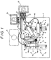
- Fig.1 is a plan view of a cutting oil supplying device.
- Fig.2 is a side view of the cutting oil supplying device of Fig.1.
- Fig.3 is a perspective view of a work supporter.
- Fig.4 is a plan view of the work supporter of Fig.3, while without a cap.
- Fig.5 is a side view of the work supporter of Fig.4.
- Fig.6 is a vertical section showing an essential part of the work supporter of Fig.3.
- Fig.7 is a plan view of a work supporter of another embodiment, while without a cap.
- Fig.8 is a side view of the work supporter of Fig.7.
- Fig.9 is a vertical section showing an essential part of the work supporter of Fig.7, while with the cap.
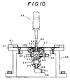
- Fig.10 is a sectional view showing a cutting oil supplying device of another embodiment.
- Fig.11 shows a cup for cutting oil: (a) shows a plan view thereof and (b) shows a vertical section thereof.
- Fig.12 shows a filter: (a) shows a plan view thereof and (b) shows a vertical section thereof.
- Fig.13 shows a ring brush: (a) shows a plan view and (b) shows a vertical section thereof.
- reference numeral 1 denotes a workbench which is fixed to a supporter 2 horizontally by fastening means 3.
- the workbench 1 is a plate having several mounting holes 5 for securing means 19a which secures a work supporter 4,4...to the workbench 1.
- a multiple spindle tapping machine 6 having four taps is installed at one side of the workbench 1.
- the work supporter 4 is fixed adjustably to the workbench 1 and positioned at a tapping position. As shown in Figs.3 to 6, the work supporter 4 has a body 7 which is substantially a rectangular solid. One end portion 8 of the body has a lower upper surface and a cylindrical hole 9a is provided in the end portion 8 which serves as a cup 9 for cutting oil.
- the cup 9 is filled with a flexible porous member 10 such as a sponge.
- a circular shaped cap having a hole for receiving the tap is capped on the upper portion of the cup 9.
- a cutting oil supplying path 12 is connected to a lower portion of the cup 9 and extends through the body to a lower portion of the other end of the body 7.
- An oil tank 15 is mounted on a stay 14 which is connected to the workbench 1 by securing means 13.
- the cutting oil supplying path 12 is connected to the oil tank 15 by a flexible pipe 16 and a valve 17.
- One side of a bottom of the body 7 extends to form an arm 18 having an elongate groove 19.
- the work supporter 4 is fixed adjustably to the hole of the workbench 1 by fastening means 19a and the position of the work supporter 4 is adjustable within the groove 19.
- the work is to be fixed on a horizontal plane surface 20 which is formed by an upper plane surface of the body 7 and an upper plane surface of the cap 11.
- Figs.7 to 9 show another embodiment of the work supporter 4.
- a circular shaped groove 21 is provided in an upper edge of the cup 9 to facilitate catch overflowed oil.
- a cutting oil withdrawing path 23 is connected to a lower portion of the groove 21 and extends through the body to an upper portion of the other end of the body 7.
- the cutting oil withdrawing path 23 is connected to a tank 24 by the flexible pipe 16.
- the tapping machine 6 When operating the tapping machine 6, first determine a position of the work supporter 4, then fix the work supporter 4 to the workbench 1 by the fastening means 19a. Next, put the work on the plane 20 and fix the work by fixing means( not shown ), then start tapping. When the tap goes through the work, getting into and out of the cup 9, the tap is wiped off by the sponge 10 and the least amount of cutting oil necessary for cooling the tap and reducing the friction between the tap and the work is applied to the tap. Therefore, the present invention prevents the oil from spreading on the work during the tapping operation. Though a very small amount of oil might remain in a thread of the work, such oil should dry quickly because volatile oil is used.
- the present invention provides a cutting oil supplying device which allows a cleaning-free tapping operation.
- Fig.10 to Fig.13 show another embodiment whose wiping means comprises a ring brush and a filter.
- a tapping machine 25 makes a thread in a work 27 using a tap 26.
- the work 27 is provided on a base 30 which is supported by a supporter 28 and secured to the supporter 20 by a screw 32.
- Reference numeral 31 denotes a positioning guide for the work 27 which is installed at a corner of the base 30.
- a cup 29 having a flange 39 is secured to an opening 33 of the base 30 by a screw 34.
- Four ports 35 are provided in a side wall of the cup 29 and another port 36 is provided in a bottom of the cup 29.
- Reference numeral 37 denotes a cap which closes the ports 35 not being used. In case of multiple spindle tapping operations, the cap 37 is removed and each port 35, 36 are connected to form a cutting oil circular path 38.
- a filter 40 is arranged in the cup 29.
- the filter 40 has a cylindrical body comprising a bottom and net body 41.
- a cutting oil mark 42 is marked in the middle of the net body 41 to show a level of the cutting oil.
- a ferrite magnet 43 is provided in the bottom of the filter 40 to facilitate collection of metal particles such as cutting dust if the work is made of steel.
- a ring brush 44 is provided above the filter 40 and secured to the cup 29.
- the ring brush 44 is the wiping member which wipes the tap 26, withdraws the metal particles and applies the least amount of cutting oil necessary for tapping to the tap 26.
- the ring brush 44 comprises a short cylindrical body 45 and a brush 46 provided in an inner surface of the body 45.
- the ring brush 44 is secured to the cup 29 by a screw 47 which is provided on an exterior surface of the body 45.
- the ring brush 44 wipes off excess oil and the metal particles from the tap 26.
- the metal particles are filtered by the filter 40.
- cutting oil can circulate through the path 38 which is connected to the ports 35, 36 respectively by a connector 48, 48.
Landscapes
- Engineering & Computer Science (AREA)
- Mechanical Engineering (AREA)
- Auxiliary Devices For Machine Tools (AREA)
Claims (12)
- Schneidölzuführungsvorrichtung, die so ausgebildet ist, daß sie Schneidöl wenigstens einem Gewindebohrer zuführen kann, der ein Werkstück schneidet, das auf einer Auflagefläche (20) angeordnet ist, welche Vorrichtung wenigstens einen Becher (9, 29) aufweist, der unterhalb der Auflagefläche (20) angeordnet ist und sich an einer Gewindeschneidposition befindet, welcher Becher (9, 29) mit dem Schneidöl gefüllt werden kann, dadurch gekennzeichnet, daß eine Wischeinrichtung (10, 44) im Becher (9, 29) vorgesehen ist, welche Wischeinrichtung (10, 44) so ausgebildet ist, daß ein Teil der Wischeinrichtung den Gewindebohrer kontaktiert, wenn dieser in den Becher eingeführt wird.
- Schneidölzuführungsvorrichtung nach Anspruch 1, bei der die Wischeinrichtung aus einem flexiblen porösen Element (10) besteht.
- Schneidölzuführungsvorrichtung nach Anspruch 1 oder 2, bei der ein Schneidölzuführungsweg (12) mit dem Becher (9) verbunden ist.
- Schneidölzuführungsvorrichtung nach Anspruch 3, bei der ein Schneidölabführungsweg (23) mit dem Becher (9) verbunden ist.
- Schneidölzuführungsvorrichtung nach Anspruch 2, welche weiterhin eine Werkbank (1), die horizontal von Füßen (2) gehalten ist, wenigstens einen Werkstückhalter (4), der einstellbar an der Werkbank (1) befestigt ist, welcher Werkstückhalter (4) einen im wesentlichen rechtwinkligen massiven Körper (7) aufweist, wobei ein Endabschnitt des Körpers (7) eine tiefer liegende obere Außenfläche (8) aufweist, der Becher (9) für das Schneidöl in einem Endabschnitt vorgesehen ist, der Becher (9) mit einem flexiblen porösen Element (10) versehen ist, eine Kappe (11) mit einem darin vorgesehenen Loch (11a) auf dem oberen Teil des Bechers (9) angeordnet ist, ein Schneidölzuführungsweg (12) mit einem unteren Teil des Bechers (9) verbunden ist und durch den Körper (7) zu einem unteren Teil des anderen Endes des Körpers (7) geht und eine obere horizontale Fläche des Körpers (7) und eine obere Fläche der Kappe (11) die Auflagefläche (20) für das Werkstück bilden.
- Schneidölzuführungsvorrichtung nach Anspruch 5, bei der die Werkbank (1) eine Platte mit wenigstens einem darin vorgesehenen Montageloch (5) aufweist und bei der eine Seite des unteren Teils des Körpers (7) so verläuft, daß ein Arm (18) mit einer langgestreckten Öffnung (19) gebildet ist.
- Schneidölzuführungsvorrichtung nach Anspruch 5 oder 6, bei der eine ringförmige Nut (21) in einem oberen Rand des Bechers (9) vorgesehen ist, um das Einfangen des überfließenden Öls zu erleichtern, und bei der ein Schneidölrückführungsweg (23) mit der ringförmigen Nut (21) verbunden ist und durch den Körper (7) zu einem oberen Teil des anderen Endes des Körpers (7) verläuft.
- Schneidölzuführungsvorrichtung nach einem der Ansprüche 2 bis 7, bei der das flexible poröse Element ein Schwamm (10) ist.
- Schneidölzuführungsvorrichtung nach Anspruch 1, bei der die Wischeinrichtung eine Ringbürste (44) ist.
- Schneidölzuführungsvorrichtung nach Anspruch 9, bei der ein Filter (40) im Becher (29) unterhalb der Ringbürste (44) vorgesehen ist.
- Schneidölzuführungsvorrichtung nach Anspruch 10, bei der das Filter (40) eine Markierung (42) aufweist, um den Pegel des Schneidöls zu zeigen, wenigstens eine Seitenöffnung (35) oberhalb der Markierung vorgesehen ist, eine untere Öffnung (36) am Boden des Bechers (29) vorgesehen ist und die Seitenöffnung (35) und die Bodenöffnung (36) zur Bildung eines Schneidölzirkulationsweges miteinander verbunden sind.
- Schneidölzuführungsvorrichtung nach Anspruch 11, bei der ein Magnet (43) in einem unteren Teil des Filters (40) vorgesehen ist.
Applications Claiming Priority (4)
| Application Number | Priority Date | Filing Date | Title |
|---|---|---|---|
| JP235376/92 | 1992-08-11 | ||
| JP4235376A JP2511772B2 (ja) | 1992-08-11 | 1992-08-11 | タッピングにおけるタップへの切削油供給装置 |
| JP35033392A JP2759731B2 (ja) | 1992-12-03 | 1992-12-03 | タッピングにおけるタップへの切削油供給装置 |
| JP350333/92 | 1992-12-03 |
Publications (2)
| Publication Number | Publication Date |
|---|---|
| EP0592020A1 EP0592020A1 (de) | 1994-04-13 |
| EP0592020B1 true EP0592020B1 (de) | 1997-10-08 |
Family
ID=26532082
Family Applications (1)
| Application Number | Title | Priority Date | Filing Date |
|---|---|---|---|
| EP93202225A Expired - Lifetime EP0592020B1 (de) | 1992-08-11 | 1993-07-27 | Schmiereinrichtung für Gewindebohrer |
Country Status (4)
| Country | Link |
|---|---|
| US (1) | US5333973A (de) |
| EP (1) | EP0592020B1 (de) |
| KR (1) | KR960013239B1 (de) |
| DE (1) | DE69314427D1 (de) |
Families Citing this family (8)
| Publication number | Priority date | Publication date | Assignee | Title |
|---|---|---|---|---|
| EP0628429B1 (de) * | 1993-06-11 | 1997-04-23 | Ferag AG | Verfahren und Vorrichtung zum Verbinden der Bogen eines mehrblättrigen Druckereiproduktes |
| US7004690B2 (en) * | 2002-10-30 | 2006-02-28 | The Boeing Company | Drill build-up remover |
| US7175371B2 (en) * | 2003-07-18 | 2007-02-13 | Vidal Robert J | Protective shield for a tool |
| GB0321316D0 (en) * | 2003-09-11 | 2003-10-15 | Thom Ivor W | Golf putter head |
| US8016522B2 (en) * | 2009-03-17 | 2011-09-13 | Lung-Chih Chen | Heat sink for drill bits of different sizes |
| DE102015211691A1 (de) * | 2015-06-24 | 2016-12-29 | Airbus Operations Gmbh | Bohrverfahren für Strukturteile sowie Auffangelement für ein derartiges Bohrverfahren |
| US10016820B2 (en) * | 2016-02-09 | 2018-07-10 | The Boeing Company | Drill plate assemblies |
| US9862066B1 (en) * | 2016-09-29 | 2018-01-09 | The Boeing Company | Systems and methods for control of foreign object debris |
Family Cites Families (8)
| Publication number | Priority date | Publication date | Assignee | Title |
|---|---|---|---|---|
| US2278886A (en) * | 1941-07-16 | 1942-04-07 | William Langbein And Brothers | Automatic oiling device |
| US2548314A (en) * | 1949-11-19 | 1951-04-10 | Sr Raymond I Kinney | Magnetic shaving collector for drills |
| US2847880A (en) * | 1953-06-29 | 1958-08-19 | Claude E Neidig | Cutting tool lubricators and cleaners |
| US3227012A (en) * | 1954-12-24 | 1966-01-04 | Jerome H Lemelson | Combination tools |
| US2855614A (en) * | 1957-12-24 | 1958-10-14 | Clarence B Simon | Self-oiling die stock |
| US4147232A (en) * | 1977-05-16 | 1979-04-03 | Boeing Commercial Airplane Company | Lubricant applicator |
| SU848281A1 (ru) * | 1979-10-10 | 1981-07-23 | Ивановский Энергетический Институтим. B.И. Ленина | Устройство дл подвода ферромагнитнойСМАзОчНО-ОХлАждАющЕй жидКОСТи |
| DE3045846C2 (de) * | 1980-12-05 | 1982-12-30 | Friedrichsfeld Gmbh, Steinzeug- Und Kunststoffwerke, 6800 Mannheim | Verfahren und Vorrichtung zur Durchführung des Verfahrens zur Bearbeitung von Platten |
-
1993
- 1993-06-09 KR KR1019930010380A patent/KR960013239B1/ko not_active Expired - Fee Related
- 1993-06-22 US US08/080,921 patent/US5333973A/en not_active Expired - Fee Related
- 1993-07-27 DE DE69314427T patent/DE69314427D1/de not_active Expired - Lifetime
- 1993-07-27 EP EP93202225A patent/EP0592020B1/de not_active Expired - Lifetime
Also Published As
| Publication number | Publication date |
|---|---|
| KR960013239B1 (ko) | 1996-10-02 |
| KR940003648A (ko) | 1994-03-12 |
| DE69314427D1 (de) | 1997-11-13 |
| US5333973A (en) | 1994-08-02 |
| EP0592020A1 (de) | 1994-04-13 |
Similar Documents
| Publication | Publication Date | Title |
|---|---|---|
| EP0592020B1 (de) | Schmiereinrichtung für Gewindebohrer | |
| EP0825446A3 (de) | Pipettenreinigungseinheit für automatische biochemische Analysiervorrichtung | |
| US4377239A (en) | Brush rack | |
| US5307696A (en) | Liquid sampling head having a removable needle body immersed in a cavity | |
| US2049394A (en) | Slideway for machine tool elements | |
| CA2066742A1 (en) | Device for taking up fluids | |
| US5940651A (en) | Drip catching apparatus for receiving excess photoresist developer solution | |
| US4400708A (en) | Disposable inker cartridge and holder therefor | |
| JPH04283040A (ja) | 工作機械 | |
| JPH0648279A (ja) | 給油機のノズル掛け | |
| US4860401A (en) | Dipstick wiper | |
| CN215964462U (zh) | 弹簧线材涂油机构 | |
| JP2513650Y2 (ja) | 洗髪洗面化粧台の水受け構造 | |
| KR100211336B1 (ko) | 엔진 오일팬의 드레인콕크 | |
| JP2759788B2 (ja) | タッピングにおけるタップへの切削油供給装置およびタッピング加工法 | |
| JPH11138387A (ja) | 加工機における工具への給油装置 | |
| KR870005673A (ko) | 절삭유 여과장치 | |
| JPS6221121Y2 (de) | ||
| KR200310720Y1 (ko) | 윤활유 공급기 | |
| SU1269917A1 (ru) | Сборный режущий инструмент | |
| JPS6133356Y2 (de) | ||
| JPS5931692Y2 (ja) | 点滴浸油装置 | |
| GB1578548A (en) | Lubricating oil seal on a sewing machine | |
| JPS5822587Y2 (ja) | 流し台 | |
| JPS6016698Y2 (ja) | 洗面器の排水路に対する異物受け具 |
Legal Events
| Date | Code | Title | Description |
|---|---|---|---|
| PUAI | Public reference made under article 153(3) epc to a published international application that has entered the european phase |
Free format text: ORIGINAL CODE: 0009012 |
|
| AK | Designated contracting states |
Kind code of ref document: A1 Designated state(s): DE FR GB |
|
| 17P | Request for examination filed |
Effective date: 19940420 |
|
| 17Q | First examination report despatched |
Effective date: 19950831 |
|
| GRAG | Despatch of communication of intention to grant |
Free format text: ORIGINAL CODE: EPIDOS AGRA |
|
| GRAH | Despatch of communication of intention to grant a patent |
Free format text: ORIGINAL CODE: EPIDOS IGRA |
|
| GRAH | Despatch of communication of intention to grant a patent |
Free format text: ORIGINAL CODE: EPIDOS IGRA |
|
| GRAA | (expected) grant |
Free format text: ORIGINAL CODE: 0009210 |
|
| AK | Designated contracting states |
Kind code of ref document: B1 Designated state(s): DE FR GB |
|
| PG25 | Lapsed in a contracting state [announced via postgrant information from national office to epo] |
Ref country code: FR Free format text: LAPSE BECAUSE OF FAILURE TO SUBMIT A TRANSLATION OF THE DESCRIPTION OR TO PAY THE FEE WITHIN THE PRESCRIBED TIME-LIMIT Effective date: 19971008 |
|
| REF | Corresponds to: |
Ref document number: 69314427 Country of ref document: DE Date of ref document: 19971113 |
|
| PG25 | Lapsed in a contracting state [announced via postgrant information from national office to epo] |
Ref country code: DE Free format text: LAPSE BECAUSE OF FAILURE TO SUBMIT A TRANSLATION OF THE DESCRIPTION OR TO PAY THE FEE WITHIN THE PRESCRIBED TIME-LIMIT Effective date: 19980109 |
|
| EN | Fr: translation not filed | ||
| PG25 | Lapsed in a contracting state [announced via postgrant information from national office to epo] |
Ref country code: GB Free format text: LAPSE BECAUSE OF NON-PAYMENT OF DUE FEES Effective date: 19980727 |
|
| PLBE | No opposition filed within time limit |
Free format text: ORIGINAL CODE: 0009261 |
|
| 26N | No opposition filed | ||
| GBPC | Gb: european patent ceased through non-payment of renewal fee |
Effective date: 19980727 |