EP0592151B1 - Interpolation temps-fréquence avec application au codage de parole à faible débit - Google Patents
Interpolation temps-fréquence avec application au codage de parole à faible débit Download PDFInfo
- Publication number
- EP0592151B1 EP0592151B1 EP93307766A EP93307766A EP0592151B1 EP 0592151 B1 EP0592151 B1 EP 0592151B1 EP 93307766 A EP93307766 A EP 93307766A EP 93307766 A EP93307766 A EP 93307766A EP 0592151 B1 EP0592151 B1 EP 0592151B1
- Authority
- EP
- European Patent Office
- Prior art keywords
- spectrum
- signal
- speech
- entry
- speech signal
- Prior art date
- Legal status (The legal status is an assumption and is not a legal conclusion. Google has not performed a legal analysis and makes no representation as to the accuracy of the status listed.)
- Expired - Lifetime
Links
Images


Classifications
-
- G—PHYSICS
- G10—MUSICAL INSTRUMENTS; ACOUSTICS
- G10L—SPEECH ANALYSIS TECHNIQUES OR SPEECH SYNTHESIS; SPEECH RECOGNITION; SPEECH OR VOICE PROCESSING TECHNIQUES; SPEECH OR AUDIO CODING OR DECODING
- G10L19/00—Speech or audio signals analysis-synthesis techniques for redundancy reduction, e.g. in vocoders; Coding or decoding of speech or audio signals, using source filter models or psychoacoustic analysis
- G10L19/02—Speech or audio signals analysis-synthesis techniques for redundancy reduction, e.g. in vocoders; Coding or decoding of speech or audio signals, using source filter models or psychoacoustic analysis using spectral analysis, e.g. transform vocoders or subband vocoders
- G10L19/0212—Speech or audio signals analysis-synthesis techniques for redundancy reduction, e.g. in vocoders; Coding or decoding of speech or audio signals, using source filter models or psychoacoustic analysis using spectral analysis, e.g. transform vocoders or subband vocoders using orthogonal transformation
-
- G—PHYSICS
- G10—MUSICAL INSTRUMENTS; ACOUSTICS
- G10L—SPEECH ANALYSIS TECHNIQUES OR SPEECH SYNTHESIS; SPEECH RECOGNITION; SPEECH OR VOICE PROCESSING TECHNIQUES; SPEECH OR AUDIO CODING OR DECODING
- G10L19/00—Speech or audio signals analysis-synthesis techniques for redundancy reduction, e.g. in vocoders; Coding or decoding of speech or audio signals, using source filter models or psychoacoustic analysis
- G10L2019/0001—Codebooks
- G10L2019/0012—Smoothing of parameters of the decoder interpolation
-
- G—PHYSICS
- G10—MUSICAL INSTRUMENTS; ACOUSTICS
- G10L—SPEECH ANALYSIS TECHNIQUES OR SPEECH SYNTHESIS; SPEECH RECOGNITION; SPEECH OR VOICE PROCESSING TECHNIQUES; SPEECH OR AUDIO CODING OR DECODING
- G10L25/00—Speech or voice analysis techniques not restricted to a single one of groups G10L15/00 - G10L21/00
- G10L25/93—Discriminating between voiced and unvoiced parts of speech signals
Definitions
- the present invention relates to a new method for high quality speech coding at low coding rates.
- the invention relates to processing voiced speech based on representing and interpolating the speech signal in the time-frequency domain.
- TLA Telecommunication Industry Association
- IS54 North-American "full rate” digital system
- CELP code-excited linear prediction
- M. R. Schroeder and B. S. Atal "Code-Excited Linear Predictive (CELP): High Quality Speech at Very Low Bit Rates," Proc. IEEE ICASSP'85, Vol. 3, pp. 937-940, March 1985; P. Kroon and E. F. Deprettere, "A Class of Analysis-by-Synthesis Predictive Coders for High Quality Speech Coding at Rates Between 4.8 and 16 Kb/s," IEEE J. on Sel. Areas in Comm., SAC-6(2), pp. 353-363, February 1988.
- Current CELP coders deliver fairly high-quality coded speech at rates of about 8 Kbps and above. However, the performance deteriorates quickly as the rate goes down to around 4 Kbps and below.
- the present invention as claimed provides a method and apparatus for the high-quality compression of speech while avoiding many of the costs and restrictions associated with prior methods.
- the present invention is illustratively based on a technique called Time-Frequency interpolation ("TFI").
- TFI illustratively forms a plurality of Linear Predictive Coding parameters characterizing a speech signal.
- TFI generates a per-sample discrete spectrum for points in the speech signal and then decimates the sequence of a discrete spectra.
- TFI interpolates the discrete spectra and generates a smooth speech signal based on the Linear Predictive Coding parameters.
- Figure 1 presents an illustrative embodiment of the present invention which encodes speech.
- Analog speech signal is digitized by sampler 101 by techniques which are well known to those skilled in the art.
- the digitized speech signal is then encoded by encoder 103 according to a prescribed rule illustratively described herein.
- Encoder 103 advantageously further operates on the encoded speech signal to prepare the speech signal for the storage or transmission channel 105.
- the received encoded sequence is decoded by decoder 107.
- a reconstructed version of the original input analog speech signal is obtained by passing the decoded speech signal through a D/A converter 109 by techniques which are well known to those skilled in the art.
- the encoding/decoding operations in the present invention advantageously use a technique called Time-Frequency Interpolation.
- a technique called Time-Frequency Interpolation An overview of an illustrative Time-Frequency Interpolation technique will be discussed in Section II before the detailed discussion of the illustrative embodiments are presented in Section III.
- Time-Frequency Representation is based on the concept of short-time per-sample discrete spectrum sequence.
- Each time n on a discrete-time axis is associated with an M(n)-point discrete spectrum.
- DFT discrete Fourier transform
- n lies in its segment, namely, n 1 (n) ⁇ n ⁇ n 2 (n).
- the time series x(n) may be over-specified by the sequence X(n,K) since, depending on the amount of segment overlapping, there may be several different ways of reconstructing x(n) from X(n,K). Exact reconstruction, however, is not the main objective in using TFR. Depending on application, the "over-specifying" feature may, in fact, be useful in synthesizing signals with certain desired properties.
- the spectrum assigned to time n may be generated in various ways to achieve various desired effects.
- the general-case spectrum sequence is denoted by Y(n,K) to distinguish between the straightforward case of Eq. (1) and more general transform operations that may utilize linear and non-linear techniques like decimation, interpolation, shifts, time (frequency) scale modification, phase manipulations and others.
- the TFR process is illustrated in Figure 2 which shows a typical sequence of spectra in a discrete time-frequency domain (n,K). Each spectrum is derived from one time-domain segment. The segments usually overlap and need not be of the same size.
- the figure also shows the corresponding signals y(n,m) in the time-time domain (n,m).
- the window functions w(n,m) are shown vertically along the n-axis and the weighted-sum signal z(m) is shown along the m-axis.
- TFR time limits
- TFR The TFR framework, as defined above is general enough to apply in many different applications.
- a few examples are signal (speech) enhancement, preand postfiltering, time scale modification and data compression.
- speech speech
- preand postfiltering the focus is on the use of TFR for low-rate speech coding.
- TFR is used here as a basic framework for spectral decimation, interpolation and vector quantization in an LPC-based speech coding algorithm.
- the next section defines the decimation-interpolation process withing the TFR framework.
- Time-frequency interpolation refers here to the process of first decimating the TFR spectra Y(n,K) along the time axis n and then interpolating missing spectra from the survivor neighbors.
- TFI refers to interpolation of the frequency spacings of the spectral components.
- TFR For the coding of voiced speech, i.e. where the vocal tract is excited by quasi periodic pulses of air, see L. R. Rabiner and R. W. Schafer, Digital Processing of Speech Signals (Prentice Hall, 1978), TFR combined with TFI provides a useful domain in which coding distortions can be made less objectionable. This is so because the spectrum of voiced speech, especially when synchronized to the speech periodicity, changes slowly and smoothly.
- the TFI approach is a natural way of exploiting these speech characteristics. It should be noted that the emphasis is on interpolation of spectra and not waveforms. However, since the spectrum is interpolated on a per-sample basis, the corresponding waveform tends to sound smooth even though it may be significantly different from the ideal (original) waveform.
- the F -1 / n operator indicates inverse DFT, taken at time n, from frequency axis K to the time axis m.
- TFI TFI
- Eq. (5) The formulation of TFI as in Eq. (5) is very general and does not point to any specific application.
- the following sections provide detailed descriptions of several embodiments of the present invention.
- four classes of TFI that may be practical for speech applications are described below. Those skilled in the art will recognize that other embodiments of the TFI application are possible.
- linear TFI is used.
- Linear TFI is the case where I n is a linear operation on its two arguments.
- the operators F -1 / n and I n which, in general do not commute, may be interchanged. This is important since performing the inverse DFT prior to interpolating may significantly reduce the cost of the entire TFI algorithm.
- Linear TFI with linear interpolation functions ⁇ (m), ⁇ (m) is simple and attractive from implementation point of view and has previously been used in similar forms see, B. W. Kleijn, "Continuous Representations in Linear Predictive Coding," Proc. IEEEICASSP'91, Vol. S1, pp. 201-204, May 1991; B. W. Kleijn, “Methods for Waveform Interpolation in Speech Coding," Digital Signal Processing, Vol. 1, pp. 215-230, 1991.
- This aspect of the invention is an important example of non-linear TFI.
- Linear TFI is based on linear combination of complex spectra. This operation does not, in general, preserve the spectral shape and may generate a poor estimate of the missing spectra. Simply stated, if A and B are two complex spectra, then, the magnitude of ⁇ A + ⁇ B may be very different from that of either A or B. In speech processing applications, the short-term spectral distortions generated by linear TFI may create objectionable auditory artifacts.
- magnitude-preserving interpolation I n (.,.) is defined so as to separately interpolate the magnitude and the phase of its arguments. Note that in this case I n and F -1 / n do not commute and the interpolated spectra have to be explicitly derived prior to taking the inverse DFT.
- the magnitude-phase approach may be pushed to an extreme case where the phase is totally ignored (set to zero). This eliminates half of the information to be coded while it still produces fairly good speech quality due to the spectral-shape preservation and the inherent smoothness of the TFI.
- the TFI rate is defined as the frequency of sampling the spectrum sequence, which is clearly 1/N.
- the discrete spectrum Y(n,K) corresponds to one M(n)-size period of y(n,m). If N > M(n), the periodically-extended parts of y(n,m) take part in the TFI process. This case is referred to as Low-Rate TFI (LR-TFI).
- LR-TFI Low-Rate TFI
- LR-TFI is mostly useful for generating near-periodic signals, particularly in low-rate speech coding.
- the TFI rate is a very important factor. There are conflicting requirements on the bit rate and the TFI rate. HR-TFI provide smooth and accurate description of the signal, but a high bit rate is needed to code the data. LR-TFI is less accurate and more prone to interpolation artifacts but a lower bit rate is required for coding the data. It seems that a good tradeoff can only be found experimentally by measuring the coder performance for different TFI rates.
- Time Scale Modification (TSM) is employed.
- TSM amounts to dilation or contraction of a continuous-time signal x(t) along the time axis.
- Eq. (9) is not a true TSM but only an approximation thereof. It, however, works fairly well for periodic signals and with a modest amount of dilation or contraction.
- This pseudo-TSM method is very useful in voiced speech processing since it allows for very fine alignment with the changing pitch period. Indeed, we make this method an integral part of the TFI algorithm by defining F -1 / n in Eq.
- n the time at which a DFT snapshot was taken over a segment of size M(n).
- m a time axis in which inverse DFT is done with time scale modification using the TSM function c(m).
- phase interpolation is performed along the m-axis and, as implied by the above notation, it may be different for each of the waveforms y(n,m).
- Various interpolation strategies may be employed, see references by Kleijn, supra . The one used in the low-rate coder will be described later.
- the boundary conditions are usually given in terms of two fundamental frequencies (pitch values).
- the DFT size is made independent of n by simply using one common size and appending zeros to all spectra shorter than M. Note that M is usually close to the local period of the signal, but the TFI allows any M.
- phase Since the phase is now independent of the DFT size, namely, of the original frequency spacing, one has to make sure that the actual spacing made by the phase ⁇ (m) does not cause spectral aliasing. This is very much dependent upon how Y(n,K) is interpolated from the boundary spectra and on how the actual size of Y(n,k) is determined.
- One advantage of the TFI system, as formulated here, is that spectral aliasing, due to excessive time-scaling, can be controlled during spectral interpolation. This is hard to do directly in the time domain.
- FCS Fractional Circular Shift
- Y'(n,K,dt) Y(n,K) e j 2 ⁇ K M(n) dt
- a final aspect of the invention deals with the use of DFT parameterization techniques.
- HR-TFI the number of terms involved per time unit may be much greater then that of the underlying signal.
- One simple way of reducing the number of terms is to non-uniformly decimate the DFT.
- Spectral smoothing techniques could also be used for this purpose. Parametrized TFI is useful in low-rate speech coding since the limited bit budget may not be sufficient for coding all the DFT terms.
- Coder 103 begins operation by processing the digitized speech signal through a classical Linear Predictive Coding (LPC) Analyzer 205 resulting in a decomposition of spectral envelope information. It is well known to those skilled in the art how to make and use the LPC analyzer. This information is represented by LPC parameters which are then quantized by the LPC Quantizer 210 and which become the coefficients for an all-pole LPC filter 220.
- LPC Linear Predictive Coding
- Voice and pitch analyzer 230 also operates on the digitized speech signal to determine if the speech is voiced or unvoiced.
- the voice and pitch analyzer 230 generates a pitch signal based on the pitch period of the speech signal for use by the Time-Frequency Interpolation (TFI) coder 235.
- the current pitch signal along with other signals as indicated in the figures, is "indexed" whereby the encoded representation of the signal is an "index" corresponding to one of a plurality of entries in a codebook. It is well known to those of ordinary skill in the art how to compress these signals using well-known techniques. The index is simply a short-hand, or compressed, method for specifying the signal.
- the indexed signals are forwarded to the channel encoder/buffer 225 so they may be properly stored or communicated over the transmission channel 105.
- the coder 103 processes and codes the digitized speech signal in one of two different modes depending on whether the current data is voiced or unvoiced.
- CELP Code-Excited Linear-Predictive
- CELP coder 215 advantageously optimizes the coded excitation signal by monitoring the output coded signal. This is represented in the figure by the dotted feedback line. In this mode, the signal is assumed to be totally aperiodic and therefore there is no attempt to exploit long-term redundancies by pitch loops or similar techniques.
- the CELP mode When the signal is declared voiced, the CELP mode is turned off and the TFI coder 235 is turned on by switch 305. The rest of this section discusses this coding mode. The various operations that take place in this mode are shown in Figure 4. The figure shows the logical progression of the TFI algorithm. Those skilled in the art will recognize that in practice, and for some specific systems, the actual flow may be somewhat different. As shown in the figure, the TFI coder is applied to the LPC residual, or LPC excitation signal, obtained by inverse-filtering the input speech with LPC inverse filter 310. Once per frame, an initial spectrum X(K) is derived by applying a DFT using the pitch-sized DFT 320 where the DFT length is determined by the current pitch signal.
- a pitched-sized DFT is advantageously used but is not required. This segment, however, may be longer than one frame.
- the spectrum is then modified by the spectral modifier 330 to reduce its size, and the modified spectrum is quantized by predictive weighted vector quantizer 340. Delay 350 is required for this quantizing operation. These operations yield the spectrum Y(N-1,K), that is, the spectrum associated with the current frame end-point.
- the quantized spectrum is then transmitted along with the current pitch period to the interpolation and alignment unit 360.
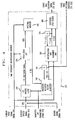
- Figure 5 illustrates a block diagram of an illustrative interpolation and alignment unit such as that shown at 360 in Figure 4.
- the current spectrum, previous quantized spectra from delay block 370, and the current pitch signal are input to this unit.
- Current spectrum, Y(N-1,K) is first enhanced by the spectral demodifier/enhancer 405 to reverse or alter the operations performed by spectral modifier 330.
- the re-modified spectrum is then aligned in the alignment unit 410 with the spectra of the previous frame by FCS operation and interpolated by the interpolation unit 420. Additionally, the phase is also interpolated.
- the unit 360 yields the spectral sequence Y' (n,K) and phase ⁇ (m) which are input to the excitation synthesizer 380.
- the spectrum is converted to a time sequence, y(n,m), by the inverse DFT unit 510, and the time sequence is windowed by the 2-dimensional windower 520 to yield the coded voice excitation signal.
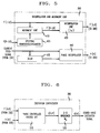
- FIG 7 illustrates block diagram speech decoding system 107 where switch 750 selects CELP decoding or TFI decoding depending on whether the speech is voiced or unvoiced.
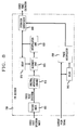
- Figure 8 illustrates a block diagram of a TFI decoder 720. Those skilled in the art will recognize that the blocks on the TFI decoder perform similar functions as the blocks of the same name in the encoder.
- TFI algorithms can be envisioned within the framework formulated so far. There is no obvious systematic way of developing the best system and lots of heuristics and experimentations are involved. One way is to start with a simple system and gradually improve it by gaining more insight to the process and by eliminating one problem at a time. Along this line, we now describe in more detail three different TFI systems.
- spectral modification advantageously amounts only to nulling the upper 20% of the DFT components: if M is the current initial DFT size (half the current pitch), then, X' (K) and Y(N-1,K) have only 0.8 M complex components.
- the purpose of this windowing is to make the following VQ operation more efficient by reducing the dimensionality.
- the spectrum is quantized by a weighted, variable-size, predictive vector quantizer. Spectral weighting is accomplished by minimizing
- H(K) is the DFT of the impulse response of a modified all-pole LPC filter. See Schroeder and Atal, supra; Kroon and Deprettere, supra.
- the quantized spectrum is now aligned with the previous spectrum by applying FCS to Y(N-1,K) as in Eq. (13). The best fractional shift is found for maximum correlation between Y'(-1,K) and Y'(N-1,K).
- System 2 was designed to remove some of the artifacts of system 1 by moving from LR-TFI to HR-TFI.
- the TFI rate is 4 times higher than that of system 1, which means that the TFI process is done every 5 msec. (40 samples). This frequent update of the spectrum allows for more accurate representation of the speech dynamics, without the excessive periodicity typical to system 1.
- Increasing the TFI rate creates a heavy burden on the quantizer since much more data has to be quantized per unit time.
- the use of magnitude-only spectrum amounts to data reduction by a factor of 2. While the spectral shape is preserved, removing the phase causes the synthesized excitation to be more spiky. This sometimes causes the output speech to sound a bit metallic. However, the advantage of achieving higher quantization performance outweighs this minor disadvantage.
- the quantization of the spectrum is performed 4 times more frequently than in the case of system 1, with essentially the same number of bits per 20 msec. interval. This is made possible by reducing the VQ dimension.
- the operation defined by Eqs. (15) and (16) means lowpass filtering.
- System 3 uses the non-linear magnitude-phase LR-TFI introduced above. This is an attempt to further improve the performance by reducing the artifacts of both system 1 and system 2.
- the initial spectrum X(K) is windowed by nulling all components indexed by K ⁇ 0.4 P and then is vector quantized.
- the quantized spectrum Y(N-1,K) is then decomposed into a magnitude vector Y(N-1,k) and a phase vector argY(N-1,K).
- a sequence of spectra is then generated by linear interpolation of the magnitudes and phases, using the ones from the previous frame:
- (1- n N )
- the vector size is K max . This is the maximum of previous and current spectrum sizes. The shorter spectrum is extended to K max by zero-padding. Note that the interpolated phases are close to those of the source spectrum only towards the frame boundaries.
- the intermediate phase vectors are somewhat arbitrary since the linear interpolation does not mean good approximation to the desired phase in any quantitative sense. However, since the magnitude spectrum is preserved, the interpolated phases act similar to the true ones in spreading the signal and, thus, the spikiness of system 2 is eliminated.
- the vector interpolation as defined above does not take care of possible spectral aliasing or distortions in the case of a large difference between the spacings of the two boundary spectra. Better interpolation schemes, in this respect, will be studied in the future.
- Each complex spectrum Y(n,K), formed by the pair ⁇ Y(n,K) , argY(n,K ) ⁇ , is FCS-ed to maximize its correlation with Y(-1,K), which yields the aligned spectra Y'(n,K).
- Inverse DFT is now performed, with the phase ⁇ (m) as in (14).
- the resulting waveforms y(n,k) are then weight-summed by the operator W n , as in (2), using simple rectangular functions w(n,m) of width Q, defined by: This means that each waveform y(n,m) contributes to the final waveform z(m) only locally.
- a good value for the window size Q can only be found experimentally by listening to processed speech.
- This disclosure deals with time-frequency interpolation (TFI) techniques and their application to low-rate coding of voiced speech.
- TFI time-frequency interpolation
- the disclosure focuses on the formulation of the general TFI framework. Within this framework, three specific TFI systems for voiced speech coding are described. The methods and algorithms have been described without reference to specific hardware or software. Instead, the individual stages have been described in such a manner that those skilled in the art can readily adapt such hardware and software as may be available or preferable for particular applications.
Landscapes
- Engineering & Computer Science (AREA)
- Physics & Mathematics (AREA)
- Spectroscopy & Molecular Physics (AREA)
- Computational Linguistics (AREA)
- Signal Processing (AREA)
- Health & Medical Sciences (AREA)
- Audiology, Speech & Language Pathology (AREA)
- Human Computer Interaction (AREA)
- Acoustics & Sound (AREA)
- Multimedia (AREA)
- Compression, Expansion, Code Conversion, And Decoders (AREA)
- Transmission Systems Not Characterized By The Medium Used For Transmission (AREA)
Claims (19)
- Procédé de codage d'un signal de parole, comprenant les étapes de :échantillonnage d'un signal de parole pour former une séquence d'échantillons;formation d'une pluralité de spectres dans un domaine temps-fréquence, chaque spectre dans ladite pluralité de spectres étant associé à un échantillon dans ladite séquence d'échantillons et chaque spectre étant généré à partir d'une pluralité d'échantillons contigus;décimation de la pluralité de spectres le long d'un axe des temps dans ledit domaine temps-fréquence pour former un ensemble de spectres ayant fait l'objet d'une décimation; etinterpolation des spectres manquants à partir dudit ensemble de spectres ayant fait l'objet d'une décimation à l'aide de l'interpolation temps-fréquence.
- Procédé de décodage d'un signal de parole codé, comprenant les étapes de :génération d'un spectre vocal codé à partir du signal de parole codé;décimation du spectre vocal codé pour former un ensemble de spectres ayant fait l'objet d'une décimation;interpolation desdits spectres ayant fait l'objet d'une décimation dans un domaine temps-fréquence pour former une séquence spectrale complète;transformation inverse de la séquence spectrale complète dudit domaine temps-fréquence en un domaine temps-temps pour former un ensemble de signaux ayant fait l'objet d'une transformation inverse, chaque signal ayant fait l'objet d'une transformation inverse dans ledit ensemble de signaux ayant fait l'objet d'une transformation inverse étant un signal bidimensionnel;fenêtrage dudit ensemble de signaux ayant fait l'objet d'une transformation inverse à l'aide d'une fonction de fenêtrage temps-temps bidimensionnelle pour former un signal fenêtré unidimensionnel; etgénération d'un signal de parole reconstruit sur la base du signal fenêtré.
- Procédé selon la revendication 2, dans lequel ladite étape d'interpolation comprend une interpolation linéaire.
- Procédé selon la revendication 2, dans lequel chaque spectre dans ladite pluralité de spectres comprend un ensemble de coefficients, chaque coefficient dans ledit ensemble de coefficients présentant une composante d'amplitude et une composante de phase, et dans lequel ladite étape d'interpolation est appliquée d'une façon non linéaire et séparément auxdites composantes d'amplitude et de phase.
- Procédé selon la revendication 1, comprenant en outre l'étape de formation d'une représentation paramétrique de taille réduite dudit ensemble de spectres ayant fait l'objet d'une décimation.
- Procédé selon la revendication 2, dans lequel ladite étape de transformation inverse se fait selon la formule
- Procédé de codage d'une pluralité de signaux de parole, dans lequel chacun desdits signaux de parole comprend une séquence d'échantillons se produisant au cours d'une trame temporelle et dans lequel lesdites trames temporelles sont contiguës, ledit procédé comprenant pour chaque trame temporelle les étapes de :génération d'une pluralité de paramètres caractérisant ledit signal de parole;quantification desdits paramètres pour former un ensemble de paramètres quantifiés;sélection d'un indice associé à une entrée dans une table de codage, laquelle entrée coïncide le mieux avec lesdits paramètres quantifiés conformément à une première mesure d'erreur;détermination d'une période de hauteur de son pour ledit signal de parole;sélection d'un indice associé à une entrée dans une table de codage, laquelle entrée coïncide le mieux avec ladite période de hauteur de son conformément à une deuxième mesure d'erreur;filtrage inverse dudit signal de parole pour produire un signal d'excitation à l'aide de paramètres de filtrage déterminés par ledit ensemble de paramètres quantifiés;transformation dudit signal d'excitation pour former un premier spectre;modification dudit premier spectre pour former un spectre modifié;quantification dudit spectre modifié pour former un spectre modifié quantifié;sélection d'un indice associé à une entrée dans une liste de codage, laquelle entrée coïncide le mieux avec ledit spectre modifié quantifié conformément à une troisième mesure d'erreur; etinterpolation dudit spectre modifié quantifié à l'aide d'une interpolation temps-fréquence.
- Procédé selon la revendication 7, dans lequel ladite étape de formation d'une pluralité de paramètres comprend l'identification de caractéristiques dudit signal de parole indiquant que la parole est de la parole voisée.
- Procédé selon la revendication 7, dans lequel ladite pluralité de paramètres sont générés par codage prédictif linéaire.
- Procédé selon la revendication 7, dans lequel ladite étape de formation d'une pluralité de paramètres caractérisant lesdits signaux de parole comprend les étapes de :identification du fait que lesdits signaux de parole représentent de la parole voisée, etlorsque ladite identification n'identifie pas de parole voisée, formation d'un deuxième signal codé à l'aide de variantes de techniques de codage.
- Procédé selon la revendication 10, dans lequel ladite variante de technique de codage est un codage prédictif linéaire excité par un code.
- Procédé selon la revendication 7, dans lequel ladite transformation se fait selon une formule de transformation de Fourier discrète avec une période approximativement égale à ladite période de hauteur de son.
- Procédé selon la revendication 7, dans lequel ladite étape de quantification du spectre modifié se fait selon une quantification vectorielle pondérée prédictive.
- Procédé selon la revendication 7, dans lequel ladite étape d'interpolation comprend en outre :l'accentuation dudit spectre modifié quantifié;l'alignement dudit spectre modifié quantifié avec un spectre d'un signal de parole provenant d'une trame précédente; etl'interpolation entre ledit spectre modifié quantifié et ledit spectre d'un signal de parole provenant d'une trame précédente pour trouver des spectres pour d'autres échantillons dans ladite trame de façon à produire une séquence spectrale complète; etledit procédé comprenant en outre les étapes de transformation inverse de ladite séquence spectrale complète pour donner un ensemble de signaux; et de fenêtrage dudit ensemble de signaux pour donner un signal fenêtré.
- Procédé selon la revendication 7, dans lequel ladite étape d'interpolation comprend en outre :l'accentuation dudit spectre modifié quantifié;l'alignement dudit spectre modifié quantifié avec un spectre d'un signal de parole provenant d'une trame précédente; etla transformation inverse dudit spectre modifié pour donner un premier signal, y(-1,m) et la transformation inverse dudit spectre dudit signal de parole provenant de ladite trame précédente pour donner un deuxième signal , y(N-1,m);l'interpolation linéaire entre ledit premier signal et ledit deuxième signal pour donner un signal final, z(m), ladite interpolation se faisant selon la formule :et où w(n,m) est une fonction de fenêtrage.
- Procédé de codage d'une pluralité de signaux de parole codés, lesdits signaux représentant :un premier indice associé à une entrée dans une table à consulter, ladite entrée représentant une pluralité de paramètres caractérisant ledit signal de parole,un deuxième indice associé à une entrée dans une deuxième table à consulter, ladite entrée représentant un signal de hauteur de son pour ledit signal de parole, etun troisième indice associé à une entrée dans une troisième table à consulter, ladite entrée représentant un spectre dudit signal de parole,ledit procédé comprenant les étapes de :détermination desdits paramètres caractérisant ledit signal de parole sur la base dudit premier indice;détermination dudit signal de hauteur de son sur la base dudit deuxième indice;détermination dudit spectre sur la base dudit troisième indice;modification et accentuation dudit spectre pour former un spectre modifié;alignement dudit spectre modifié avec le spectre d'un signal de parole provenant d'une trame précédente;interpolation entre ledit spectre et le spectre d'un signal de parole provenant d'une trame précédente pour donner une séquence spectrale complète;transformation inverse de ladite séquence spectrale complète pour donner un ensemble de signaux;fenêtrage dudit ensemble de signaux pour donner un signal fenêtré; etfiltrage dudit signal fenêtré, lesdites caractéristiques de filtrage étant déterminées par lesdits paramètres.
- Système de codage d'une pluralité de signaux de parole, dans lequel chacun desdits signaux de parole comprend une séquence d'échantillons se produisant au cours d'une trame temporelle et dans lequel lesdites trames temporelles sont contiguës, ledit système comprenant :un moyen (205) pour générer une pluralité de paramètres caractérisant ledit signal de parole;un moyen (210) pour quantifier lesdits paramètres pour former un ensemble de paramètres quantifiés et pour sélectionner un indice associé à une entrée dans une table de codage, laquelle entrée coïncide le mieux avec lesdits paramètres quantifiés conformément à une première mesure d'erreur;un moyen (230) pour déterminer une période de hauteur de son pour ledit signal de parole et pour sélectionner un indice associé à une entrée dans une table de codage, laquelle entrée coïncide le mieux avec ladite période de hauteur de son conformément à une deuxième mesure d'erreur;un moyen (310) pour réaliser le filtrage inverse dudit signal de parole pour produire un signal d'excitation, ledit moyen pour réaliser un filtrage inverse comprenant un filtre avec des paramètres de filtrage déterminés par ledit ensemble de paramètres quantifiés;un moyen (320) pour transformer ledit signal d'excitation pour former un premier spectre;un moyen (330) pour modifier ledit premier spectre pour former un spectre modifié;un moyen (340) pour quantifier ledit spectre modifié pour former un spectre modifié quantifié et pour sélectionner un indice associé à une entrée dans une liste de codage, laquelle entrée coïncide le mieux avec ledit spectre modifié quantifié conformément à une troisième mesure d'erreur; etun moyen (360) pour interpoler ledit spectre modifié quantifié à l'aide d'une interpolation temps-fréquence.
- Système selon la revendication 17, dans lequel ledit moyen pour interpoler comprend en outre :un moyen (405) pour accentuer ledit spectre modifié quantifié;un moyen (410) pour aligner ledit spectre modifié quantifié avec un spectre d'un signal de parole provenant d'une trame précédente; etun moyen (420) pour interpoler entre ledit spectre modifié quantifié et ledit spectre d'un signal de parole provenant d'une trame précédente pour trouver des spectres pour d'autres échantillons dans ladite trame de façon à produire une séquence spectrale complète; etledit système comprenant en outre un moyen (510) pour réaliser la transformation inverse de ladite séquence spectrale complète pour donner un ensemble de signaux et un moyen (520) pour fenêtrer ledit ensemble de signaux pour donner un signal fenêtré.
- Système de décodage d'une pluralité de signaux de parole codés, lesdits signaux représentant :un premier indice associé à une entrée dans une table à consulter, ladite entrée représentant une pluralité de paramètres caractérisant ledit signal de parole,un deuxième indice associé à une entrée dans une deuxième table à consulter, ladite entrée représentant un signal de hauteur de son pour ledit signal de parole, etun troisième indice associé à une entrée dans une troisième table à consulter, ladite entrée représentant un spectre dudit signal de parole,ledit système comprenant :un moyen (710) pour déterminer lesdits paramètres caractérisant ledit signal de parole sur la base dudit premier indice;un moyen (730) pour déterminer ledit signal de hauteur de son sur la base dudit deuxième indice;un moyen (725) pour déterminer ledit spectre sur la base dudit troisième indice;un moyen (810) pour modifier et accentuer ledit spectre pour former un spectre modifié;un moyen (825) pour aligner ledit spectre modifié avec le spectre d'un signal de parole provenant d'une trame précédente;un moyen (830) pour interpoler entre ledit spectre et le spectre d'un signal de parole provenant d'une trame précédente pour donner une séquence spectrale complète;un moyen (840, 510) pour réaliser la transformation inverse de ladite séquence spectrale complète pour donner un ensemble de signaux;un moyen (840, 520) pour fenêtrer ledit ensemble de signaux pour donner un signal fenêtré; etun moyen (840) pour filtrer ledit signal fenêtré, lesdites caractéristiques de filtrage étant déterminées par lesdits paramètres.
Applications Claiming Priority (2)
| Application Number | Priority Date | Filing Date | Title |
|---|---|---|---|
| US95930592A | 1992-10-09 | 1992-10-09 | |
| US959305 | 1992-10-09 |
Publications (2)
| Publication Number | Publication Date |
|---|---|
| EP0592151A1 EP0592151A1 (fr) | 1994-04-13 |
| EP0592151B1 true EP0592151B1 (fr) | 2000-03-15 |
Family
ID=25501895
Family Applications (1)
| Application Number | Title | Priority Date | Filing Date |
|---|---|---|---|
| EP93307766A Expired - Lifetime EP0592151B1 (fr) | 1992-10-09 | 1993-09-30 | Interpolation temps-fréquence avec application au codage de parole à faible débit |
Country Status (8)
| Country | Link |
|---|---|
| US (1) | US5577159A (fr) |
| EP (1) | EP0592151B1 (fr) |
| JP (1) | JP3335441B2 (fr) |
| CA (1) | CA2105269C (fr) |
| DE (1) | DE69328064T2 (fr) |
| FI (1) | FI934424L (fr) |
| MX (1) | MX9306142A (fr) |
| NO (1) | NO933535L (fr) |
Families Citing this family (24)
| Publication number | Priority date | Publication date | Assignee | Title |
|---|---|---|---|---|
| JP3137805B2 (ja) * | 1993-05-21 | 2001-02-26 | 三菱電機株式会社 | 音声符号化装置、音声復号化装置、音声後処理装置及びこれらの方法 |
| US5839102A (en) * | 1994-11-30 | 1998-11-17 | Lucent Technologies Inc. | Speech coding parameter sequence reconstruction by sequence classification and interpolation |
| US5991725A (en) * | 1995-03-07 | 1999-11-23 | Advanced Micro Devices, Inc. | System and method for enhanced speech quality in voice storage and retrieval systems |
| US5682462A (en) * | 1995-09-14 | 1997-10-28 | Motorola, Inc. | Very low bit rate voice messaging system using variable rate backward search interpolation processing |
| US6591240B1 (en) * | 1995-09-26 | 2003-07-08 | Nippon Telegraph And Telephone Corporation | Speech signal modification and concatenation method by gradually changing speech parameters |
| DE69629485T2 (de) * | 1995-10-20 | 2004-06-09 | America Online, Inc. | Kompressionsystem für sich wiederholende töne |
| US5828994A (en) * | 1996-06-05 | 1998-10-27 | Interval Research Corporation | Non-uniform time scale modification of recorded audio |
| JP3266819B2 (ja) * | 1996-07-30 | 2002-03-18 | 株式会社エイ・ティ・アール人間情報通信研究所 | 周期信号変換方法、音変換方法および信号分析方法 |
| JP4121578B2 (ja) * | 1996-10-18 | 2008-07-23 | ソニー株式会社 | 音声分析方法、音声符号化方法および装置 |
| JPH10124092A (ja) * | 1996-10-23 | 1998-05-15 | Sony Corp | 音声符号化方法及び装置、並びに可聴信号符号化方法及び装置 |
| US6377914B1 (en) | 1999-03-12 | 2002-04-23 | Comsat Corporation | Efficient quantization of speech spectral amplitudes based on optimal interpolation technique |
| JP3576936B2 (ja) * | 2000-07-21 | 2004-10-13 | 株式会社ケンウッド | 周波数補間装置、周波数補間方法及び記録媒体 |
| DE10036703B4 (de) * | 2000-07-27 | 2005-12-29 | Rohde & Schwarz Gmbh & Co. Kg | Verfahren und Vorrichtung zur Korrektur eines Resamplers |
| WO2002035517A1 (fr) * | 2000-10-24 | 2002-05-02 | Kabushiki Kaisha Kenwood | Appareil et procédé pour interpoler un signal |
| JP3887531B2 (ja) * | 2000-12-07 | 2007-02-28 | 株式会社ケンウッド | 信号補間装置、信号補間方法及び記録媒体 |
| WO2003003345A1 (fr) * | 2001-06-29 | 2003-01-09 | Kabushiki Kaisha Kenwood | Dispositif et procede d'interpolation des composantes de frequence d'un signal |
| JP3881932B2 (ja) * | 2002-06-07 | 2007-02-14 | 株式会社ケンウッド | 音声信号補間装置、音声信号補間方法及びプログラム |
| FR2891100B1 (fr) * | 2005-09-22 | 2008-10-10 | Georges Samake | Codec audio utilisant la transformation de fourier rapide, le recouvrement partiel et une decomposition en deux plans basee sur l'energie. |
| DE102007003187A1 (de) * | 2007-01-22 | 2008-10-02 | Fraunhofer-Gesellschaft zur Förderung der angewandten Forschung e.V. | Vorrichtung und Verfahren zum Erzeugen eines zu sendenden Signals oder eines decodierten Signals |
| EP2214161A1 (fr) * | 2009-01-28 | 2010-08-04 | Fraunhofer-Gesellschaft zur Förderung der angewandten Forschung e.V. | Appareil, procédé et programme informatique pour effectuer un mélange élévateur d'un signal audio de mélange abaisseur |
| CN102414742B (zh) | 2009-04-30 | 2013-12-25 | 杜比实验室特许公司 | 低复杂度听觉事件边界检测 |
| TWI506583B (zh) * | 2013-12-10 | 2015-11-01 | 國立中央大學 | 分析系統及其方法 |
| US10354422B2 (en) * | 2013-12-10 | 2019-07-16 | National Central University | Diagram building system and method for a signal data decomposition and analysis |
| US11287310B2 (en) | 2019-04-23 | 2022-03-29 | Computational Systems, Inc. | Waveform gap filling |
Family Cites Families (13)
| Publication number | Priority date | Publication date | Assignee | Title |
|---|---|---|---|---|
| JPS60239798A (ja) * | 1984-05-14 | 1985-11-28 | 日本電気株式会社 | 音声信号符号化/復号化装置 |
| US4937873A (en) * | 1985-03-18 | 1990-06-26 | Massachusetts Institute Of Technology | Computationally efficient sine wave synthesis for acoustic waveform processing |
| CA1323934C (fr) * | 1986-04-15 | 1993-11-02 | Tetsu Taguchi | Appareil de traitement de paroles |
| IT1195350B (it) * | 1986-10-21 | 1988-10-12 | Cselt Centro Studi Lab Telecom | Procedimento e dispositivo per la codifica e decodifica del segnale vocale mediante estrazione di para metri e tecniche di quantizzazione vettoriale |
| US4910781A (en) * | 1987-06-26 | 1990-03-20 | At&T Bell Laboratories | Code excited linear predictive vocoder using virtual searching |
| CA1328509C (fr) * | 1988-03-28 | 1994-04-12 | Tetsu Taguchi | Appareil predictif lineaire pour l'analyse et la synthese vocales |
| GB2235354A (en) * | 1989-08-16 | 1991-02-27 | Philips Electronic Associated | Speech coding/encoding using celp |
| JP3102015B2 (ja) * | 1990-05-28 | 2000-10-23 | 日本電気株式会社 | 音声復号化方法 |
| US5138661A (en) * | 1990-11-13 | 1992-08-11 | General Electric Company | Linear predictive codeword excited speech synthesizer |
| US5127053A (en) * | 1990-12-24 | 1992-06-30 | General Electric Company | Low-complexity method for improving the performance of autocorrelation-based pitch detectors |
| DE69233794D1 (de) * | 1991-06-11 | 2010-09-23 | Qualcomm Inc | Vocoder mit veränderlicher Bitrate |
| US5327520A (en) * | 1992-06-04 | 1994-07-05 | At&T Bell Laboratories | Method of use of voice message coder/decoder |
| US5351338A (en) * | 1992-07-06 | 1994-09-27 | Telefonaktiebolaget L M Ericsson | Time variable spectral analysis based on interpolation for speech coding |
-
1993
- 1993-08-31 CA CA002105269A patent/CA2105269C/fr not_active Expired - Fee Related
- 1993-09-30 EP EP93307766A patent/EP0592151B1/fr not_active Expired - Lifetime
- 1993-09-30 DE DE69328064T patent/DE69328064T2/de not_active Expired - Lifetime
- 1993-10-01 MX MX9306142A patent/MX9306142A/es not_active IP Right Cessation
- 1993-10-04 NO NO933535A patent/NO933535L/no not_active Application Discontinuation
- 1993-10-08 FI FI934424A patent/FI934424L/fi unknown
- 1993-10-08 JP JP27601393A patent/JP3335441B2/ja not_active Expired - Lifetime
-
1995
- 1995-05-24 US US08/449,184 patent/US5577159A/en not_active Expired - Lifetime
Also Published As
| Publication number | Publication date |
|---|---|
| US5577159A (en) | 1996-11-19 |
| FI934424A7 (fi) | 1994-04-10 |
| MX9306142A (es) | 1994-06-30 |
| NO933535D0 (no) | 1993-10-04 |
| DE69328064T2 (de) | 2000-09-07 |
| JP3335441B2 (ja) | 2002-10-15 |
| CA2105269C (fr) | 1998-08-25 |
| EP0592151A1 (fr) | 1994-04-13 |
| NO933535L (no) | 1994-04-11 |
| FI934424L (fi) | 1994-04-10 |
| DE69328064D1 (de) | 2000-04-20 |
| CA2105269A1 (fr) | 1994-04-10 |
| JPH06222799A (ja) | 1994-08-12 |
| FI934424A0 (fi) | 1993-10-08 |
Similar Documents
| Publication | Publication Date | Title |
|---|---|---|
| EP0592151B1 (fr) | Interpolation temps-fréquence avec application au codage de parole à faible débit | |
| JP5978218B2 (ja) | 低ビットレート低遅延の一般オーディオ信号の符号化 | |
| KR100873836B1 (ko) | Celp 트랜스코딩 | |
| US5903866A (en) | Waveform interpolation speech coding using splines | |
| KR100957265B1 (ko) | 잔여분 변경에 의한 보코더 내부의 프레임들을 시간 와핑하는 시스템 및 방법 | |
| US8538747B2 (en) | Method and apparatus for speech coding | |
| EP1313091B1 (fr) | Procédés et système informatique pour l'analyse, la synthèse et la quantisation de la parole. | |
| US20060173675A1 (en) | Switching between coding schemes | |
| WO2001061687A1 (fr) | Codec de parole a large bande utilisant differentes frequences d'echantillonnage | |
| JP2003044097A (ja) | 音声信号および音楽信号を符号化する方法 | |
| EP0865029B1 (fr) | Interpolation de formes d'onde par décomposition en bruit et en signaux périodiques | |
| EP1096476B1 (fr) | Décodage de la parole | |
| KR20040095205A (ko) | Celp를 기반으로 하는 음성 코드간 변환코딩 방식 | |
| JP3598111B2 (ja) | 広帯域音声復元装置 | |
| JPH05232995A (ja) | 一般化された合成による分析音声符号化方法と装置 | |
| JP3560964B2 (ja) | 広帯域音声復元装置及び広帯域音声復元方法及び音声伝送システム及び音声伝送方法 | |
| WO2025026548A1 (fr) | Codage et décodage de signaux audio | |
| JP3598112B2 (ja) | 広帯域音声復元方法及び広帯域音声復元装置 | |
| JP2004046238A (ja) | 広帯域音声復元装置及び広帯域音声復元方法 | |
| JP2004355018A (ja) | 広帯域音声復元方法及び広帯域音声復元装置 | |
| JP2004341551A (ja) | 広帯域音声復元方法及び広帯域音声復元装置 | |
| HK1093592B (en) | Speech signal decoding |
Legal Events
| Date | Code | Title | Description |
|---|---|---|---|
| PUAI | Public reference made under article 153(3) epc to a published international application that has entered the european phase |
Free format text: ORIGINAL CODE: 0009012 |
|
| AK | Designated contracting states |
Kind code of ref document: A1 Designated state(s): CH DE FR GB IT LI NL SE |
|
| RAP3 | Party data changed (applicant data changed or rights of an application transferred) |
Owner name: AT&T CORP. |
|
| 17P | Request for examination filed |
Effective date: 19940928 |
|
| 17Q | First examination report despatched |
Effective date: 19970602 |
|
| GRAG | Despatch of communication of intention to grant |
Free format text: ORIGINAL CODE: EPIDOS AGRA |
|
| GRAG | Despatch of communication of intention to grant |
Free format text: ORIGINAL CODE: EPIDOS AGRA |
|
| GRAG | Despatch of communication of intention to grant |
Free format text: ORIGINAL CODE: EPIDOS AGRA |
|
| GRAH | Despatch of communication of intention to grant a patent |
Free format text: ORIGINAL CODE: EPIDOS IGRA |
|
| GRAH | Despatch of communication of intention to grant a patent |
Free format text: ORIGINAL CODE: EPIDOS IGRA |
|
| GRAA | (expected) grant |
Free format text: ORIGINAL CODE: 0009210 |
|
| RIC1 | Information provided on ipc code assigned before grant |
Free format text: 7G 10L 19/06 A |
|
| AK | Designated contracting states |
Kind code of ref document: B1 Designated state(s): CH DE FR GB IT LI NL SE |
|
| PG25 | Lapsed in a contracting state [announced via postgrant information from national office to epo] |
Ref country code: LI Free format text: LAPSE BECAUSE OF NON-PAYMENT OF DUE FEES Effective date: 20000315 Ref country code: CH Free format text: LAPSE BECAUSE OF NON-PAYMENT OF DUE FEES Effective date: 20000315 |
|
| REG | Reference to a national code |
Ref country code: CH Ref legal event code: EP |
|
| ITF | It: translation for a ep patent filed | ||
| REF | Corresponds to: |
Ref document number: 69328064 Country of ref document: DE Date of ref document: 20000420 |
|
| ET | Fr: translation filed | ||
| REG | Reference to a national code |
Ref country code: CH Ref legal event code: PL |
|
| PLBE | No opposition filed within time limit |
Free format text: ORIGINAL CODE: 0009261 |
|
| 26N | No opposition filed | ||
| REG | Reference to a national code |
Ref country code: GB Ref legal event code: IF02 |
|
| PGFP | Annual fee paid to national office [announced via postgrant information from national office to epo] |
Ref country code: DE Payment date: 20090922 Year of fee payment: 17 |
|
| REG | Reference to a national code |
Ref country code: DE Ref legal event code: R119 Ref document number: 69328064 Country of ref document: DE Effective date: 20110401 |
|
| PG25 | Lapsed in a contracting state [announced via postgrant information from national office to epo] |
Ref country code: DE Free format text: LAPSE BECAUSE OF NON-PAYMENT OF DUE FEES Effective date: 20110401 |
|
| PGFP | Annual fee paid to national office [announced via postgrant information from national office to epo] |
Ref country code: FR Payment date: 20120119 Year of fee payment: 20 |
|
| PGFP | Annual fee paid to national office [announced via postgrant information from national office to epo] |
Ref country code: IT Payment date: 20111230 Year of fee payment: 20 |
|
| PGFP | Annual fee paid to national office [announced via postgrant information from national office to epo] |
Ref country code: NL Payment date: 20120103 Year of fee payment: 20 |
|
| PGFP | Annual fee paid to national office [announced via postgrant information from national office to epo] |
Ref country code: GB Payment date: 20120810 Year of fee payment: 20 Ref country code: SE Payment date: 20120810 Year of fee payment: 20 |
|
| REG | Reference to a national code |
Ref country code: NL Ref legal event code: V4 Effective date: 20130930 |
|
| REG | Reference to a national code |
Ref country code: GB Ref legal event code: PE20 Expiry date: 20130929 |
|
| PG25 | Lapsed in a contracting state [announced via postgrant information from national office to epo] |
Ref country code: GB Free format text: LAPSE BECAUSE OF EXPIRATION OF PROTECTION Effective date: 20130929 |
|
| REG | Reference to a national code |
Ref country code: SE Ref legal event code: EUG |
|
| REG | Reference to a national code |
Ref country code: GB Ref legal event code: 732E Free format text: REGISTERED BETWEEN 20160804 AND 20160810 |
|
| REG | Reference to a national code |
Ref country code: GB Ref legal event code: 732E Free format text: REGISTERED BETWEEN 20160811 AND 20160817 |
|
| REG | Reference to a national code |
Ref country code: GB Ref legal event code: 732E Free format text: REGISTERED BETWEEN 20160818 AND 20160824 |
|
| REG | Reference to a national code |
Ref country code: FR Ref legal event code: TP Owner name: GOOGLE INC., US Effective date: 20180129 |
|
| REG | Reference to a national code |
Ref country code: FR Ref legal event code: CD Owner name: GOOGLE LLC, US Effective date: 20180620 |