EP0592229B1 - Verfahren zur Mehrfehlerkorrektur - Google Patents
Verfahren zur Mehrfehlerkorrektur Download PDFInfo
- Publication number
- EP0592229B1 EP0592229B1 EP93308005A EP93308005A EP0592229B1 EP 0592229 B1 EP0592229 B1 EP 0592229B1 EP 93308005 A EP93308005 A EP 93308005A EP 93308005 A EP93308005 A EP 93308005A EP 0592229 B1 EP0592229 B1 EP 0592229B1
- Authority
- EP
- European Patent Office
- Prior art keywords
- error
- producing
- erasure
- correcting
- code
- Prior art date
- Legal status (The legal status is an assumption and is not a legal conclusion. Google has not performed a legal analysis and makes no representation as to the accuracy of the status listed.)
- Expired - Lifetime
Links
Images


Classifications
-
- H—ELECTRICITY
- H03—ELECTRONIC CIRCUITRY
- H03M—CODING; DECODING; CODE CONVERSION IN GENERAL
- H03M13/00—Coding, decoding or code conversion, for error detection or error correction; Coding theory basic assumptions; Coding bounds; Error probability evaluation methods; Channel models; Simulation or testing of codes
-
- G—PHYSICS
- G11—INFORMATION STORAGE
- G11B—INFORMATION STORAGE BASED ON RELATIVE MOVEMENT BETWEEN RECORD CARRIER AND TRANSDUCER
- G11B20/00—Signal processing not specific to the method of recording or reproducing; Circuits therefor
- G11B20/10—Digital recording or reproducing
- G11B20/18—Error detection or correction; Testing, e.g. of drop-outs
- G11B20/1806—Pulse code modulation systems for audio signals
- G11B20/1809—Pulse code modulation systems for audio signals by interleaving
-
- H—ELECTRICITY
- H03—ELECTRONIC CIRCUITRY
- H03M—CODING; DECODING; CODE CONVERSION IN GENERAL
- H03M13/00—Coding, decoding or code conversion, for error detection or error correction; Coding theory basic assumptions; Coding bounds; Error probability evaluation methods; Channel models; Simulation or testing of codes
- H03M13/03—Error detection or forward error correction by redundancy in data representation, i.e. code words containing more digits than the source words
- H03M13/05—Error detection or forward error correction by redundancy in data representation, i.e. code words containing more digits than the source words using block codes, i.e. a predetermined number of check bits joined to a predetermined number of information bits
- H03M13/13—Linear codes
- H03M13/15—Cyclic codes, i.e. cyclic shifts of codewords produce other codewords, e.g. codes defined by a generator polynomial, Bose-Chaudhuri-Hocquenghem [BCH] codes
- H03M13/151—Cyclic codes, i.e. cyclic shifts of codewords produce other codewords, e.g. codes defined by a generator polynomial, Bose-Chaudhuri-Hocquenghem [BCH] codes using error location or error correction polynomials
-
- G—PHYSICS
- G11—INFORMATION STORAGE
- G11B—INFORMATION STORAGE BASED ON RELATIVE MOVEMENT BETWEEN RECORD CARRIER AND TRANSDUCER
- G11B20/00—Signal processing not specific to the method of recording or reproducing; Circuits therefor
- G11B20/10—Digital recording or reproducing
- G11B20/14—Digital recording or reproducing using self-clocking codes
- G11B20/1403—Digital recording or reproducing using self-clocking codes characterised by the use of two levels
- G11B20/1423—Code representation depending on subsequent bits, e.g. delay modulation, double density code, Miller code
- G11B20/1426—Code representation depending on subsequent bits, e.g. delay modulation, double density code, Miller code conversion to or from block codes or representations thereof
Definitions
- the present invention relates to an error correcting method and, more particularly, to a multiple error correcting method for correcting erroneous symbols included in data which is encoded in accordance with an error correcting code, and then modulated based on a modulation code such as eight-to-fourteen modulation (EFM), eight-to-ten modulation (ETM), etc.
- a modulation code such as eight-to-fourteen modulation (EFM), eight-to-ten modulation (ETM), etc.
- audio data is encoded in accordance with the C1/C2 cross interleave product code.
- audio data with a plurality symbols is first encoded in accordance with a second Reed-Solomon code (C2 code) capable of correcting triple errors, interleaved according to a predetermined order, and then encoded in accordance with a first Reed-Solomon code (C I code) capable of correcting double errors.
- C2 code Reed-Solomon code
- C I code first Reed-Solomon code
- a double-error correcting method or a quadruple-erasure correcting method is performed for decoding the data encoded based on the first Reed-Solomon code
- a double-error correcting method or a sixfold-erasure correcting method are performed for decoding the data encoded based on the second Reed-Solomon code, under the constraint of real-time processing.
- an erasure is an erroneous symbol whose location is known.
- a symbol is a sequence of adjacent binary digits operated upon as a unit, and is the constitutional element of a word.
- the positions of two or more multiple-errors can be detected by a chain search algorithm.
- the calculation for the chain search algorithm must be repeatedly performed as many times as the number of symbols included in a word.
- a double-error correction and a quadruple-erasure correction can be easily performed, but a triple (or more) error correction cannot be performed.
- EP-A-0,185,425 discloses a method of decoding a repeatedly accessible information stream which is protected by a symbol-correction code.
- EP-A-0,136,604 discloses an error correcting method using a product code and a flag scheme.
- US 4 675 869 discloses a Reed-Solomon encoder and decoder including a modulation and demodulation stage.
- a flag bit is generated which acts as an indication of whether a symbol satisfies the modulation rules and therefore whether the symbol should be treated as reliable or unreliable.
- Syndrome symbols are formed subsequently, and these syndrome symbols are used by an erasure locator which provides a signal indicating the number of erasure symbols, as well as a flag indicating whether the permissible number of erasure symbols has been exceeded.
- a first set of syndrome symbols are used to determine the error positions, whereas the error or erasure values are determined from a second set of syndrome symbols.
- An object of the present invention is to provide a multiple error correcting method for correcting multiple erroneous symbols.
- Another object of the present invention is to provide a multiple error correcting method which can produce the error locations of three or more erroneous symbols and is easily performed in a Galois Field calculator in real time.
- a multiple error correcting method for correcting erroneous symbols included in data encoded in accordance with an error correcting code and then modulated in accordance with a modulation code comprising the steps of: demodulating the data in accordance with the modulation code and producing demodulated data with a demodulation flag indicating whether demodulation is possible; producing syndromes using a receiving word constituted by a plurality of said demodulated data based on said error correcting code; and generating the number of erroneous symbols included in said receiving word based on said syndromes, wherein the number of erasures included in said receiving.
- the method further comprises: determining the error form of the receiving word based on the number of erroneous symbols and the number of erasures wherein the error form may comprise one of a pure error form, a pure erasure form and a composite error form; and correcting the receiving word based on said error correcting code and said error form.
- data is sequentially encoded by means of a second error correcting code and a first error correcting code
- the method comprises the steps of: producing first syndromes using a first receiving word constituted by a plurality of said demodulated symbols in accordance with said first error correcting code; determining the first error form of the first receiving word based on said first syndromes and demodulation flags therein; first error-correcting for correcting the first receiving word based on said first error correcting code and the first error form, and then producing a decoded data including a plurality of error corrected symbols and error flags thereof indicating whether the symbol is correct; producing second syndromes using a second receiving word including a plurality of said error corrected symbols in accordance with said second error correcting code; determining the second error form of the second receiving word based on said second syndromes and said error flags therein; and second-error-correcting for correcting the second receiving word based on said second error correcting code and the second error form.
- data is encoded based on a Reed-Solomon code capable of correcting t -multiple erroneous symbols
- Fig.1 is a schematic diagram of the digital audio recording system.
- the digital audio recording system includes an analog-to-digital converter 101, a source encoder 102, an error-correcting encoder 103, a modulator 104, a signal encoder 105 and a recording medium 106.
- An audio signal is converted into digital data through analog-to-digital converter 101.
- This digital data is applied to source encoder 102, to be compressed in accordance with a specified algorithm.
- the compressed data is applied to error-correcting encoder 103, whereby it is encoded in accordance with an error code scheme such as C1/C2 cross interleave product code.
- Modulator 104 receives the output of error-correcting encoder 103 and then modulates the output based on a modulation code such as an EFM or ETM code.
- Modulation code is also called run-length limited code, which constrains a run-length of 1 and/or 0 in binary sequence to a predetermined number.
- the EFM transforms 8-bit data into 14-bit data with run-length constraints
- the ETM transforms 8-bit data into 10-bit data with run-length constraints.
- Binary information supplied from modulator 104 is recorded on recording medium 106 such as magnetic tape and magnetic disk in the form of a coded binary waveform.
- This coded binary waveform includes a non-return-to-zero (NRZ) coded waveform and a modified non-return-to-zero (NRZI) coded waveform.
- NRZ non-return-to-zero
- NRZI modified non-return-to-zero
- Fig.2 is a flowchart which illustrates the operation of the error-correcting encoder shown in Fig.1.
- step 201 C2 coding is performed, which is for encoding the data supplied from source encoder 102 in accordance with a second Reed-Solomon code capable of correcting double errors to produce C2 code words which include a plurality of symbols.
- the plurality of symbols included in the C2 code words are then interleaved in predetermined order in step 202.
- step 203 C1 encoding is performed, which is for encoding the interleaved data in accordance with a first Reed-Solomon code capable of correcting triple errors.
- Fig.3 illustrates memory map of the C1/C2 cross interleave product code, wherein the symbols arranged horizontally constitute a second code word concerning the C2 code and the symbols arranged vertically constitute a first code word concerning the C1 code.
- the C2 code is a Reed-Solomon code as denoted by RS(32,26,7) which is capable of correcting triple erroneous symbols and the C1 code is a Reed-Solomon code as denoted by RS(24,20,5) which is capable of correcting double erroneous symbols.
- each C1 code word includes 24 symbols and each C2 code word includes 32 symbols.
- each C1 code words include 20 information symbols and four parity symbols (called P parity symbols), and each C2 code word includes 26 information symbols and six parity symbols (called Q parity symbols).
- C2 coding generates the Q parity symbols which, together with the information symbols for the C2 code words, constitute the information symbols for a C1 code word.
- the P parity symbols are generated in C1 coding.
- Each symbol is comprised of 8-bits.
- D #,# denotes the symbols included in the data supplied from source encoder 102
- P #,# denotes P parity symbols
- Q #,# denotes Q parity symbols.
- Fig.4 is a flowchart illustrating the multiple error correcting method according to an embodiment of the present invention.
- step 401 the data made by encoding based on an error correcting code and then modulating in accordance with a modulation code, is first demodulated based on the modulation code.
- 14-bit data is demodulated into 8-bit data in accordance with EFM demodulation
- 10-bit data is demodulated into 8-bit data accordance with ETM demodulation.
- the demodulated 8-bit data i.e., a demodulated symbol
- can be set as a special bit pattern e.g., "00000000" or "11111111”
- step 402 demodulation flags are produced, which signify whether or not the demodulation of each symbol is possible. Accordingly, after step 402, each symbol has one bit beyond the basic eight, which acts as a demodulation flag.
- the demodulation flag bit may be set to "1" in the case of demodulation being impossible and to "0" in the case of demodulation being possible.
- step 403 the demodulated data is decoded using the demodulation flag of each symbol in accordance with the error correcting code.
- the demodulation flag plays an important role in producing the error location of an error location polynomial.
- Fig.5 is a flowchart for explaining step 403 shown in Fig.4, under the constraint of the error correcting code being a Reed-Solomon code.
- syndromes are produced based on the error correcting code and the demodulated 8-bit data.
- the receiving polynomial is 24 symbols if the Reed-Solomon code is a RS(24,20,5), and the receiving polynomial is 32 symbols if the Reed-Solomon code is a RS(32.26,7).
- the number of syndromes is 4 t or more, provided that the Reed-Solomon code is for correcting t errors, because the total number of erroneous symbols is 2 t .
- the erroneous symbols includes errors and erasures.
- step 502 the error form of the receiving polynomial is determined based on the numbers of syndromes and erasures, erasure being representative of symbols having a demodulation flag of "1.”
- Step 503 is for producing error locations of the error location polynomial, using the demodulation flag. Error locations represent the location of the erroneous symbols in the receiving polynomial. Accordingly, if the nth symbol in the receiving polynomial has the demodulation flag set to "1," the error location is "n.”
- Step 504 is for producing error values using the error locations based on the Reed-Solomon code
- step 505 is for correcting the receiving polynomial in accordance with the error locations and the error values.
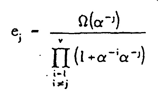
- the error values be e 1 , e 2 ..., e v
- the error presumption polynomial ⁇ (x) be ⁇ v + ( ⁇ v S 0 + ⁇ v-1 )x + ( ⁇ v S 1 + ⁇ v-1 S 0 + ⁇ v-2 )x 2 + ... + ( ⁇ v S v-1 + ⁇ v-1 S v-2 +...+1)x v
- the error values are produced in accordance with the following:
- Fig.6 is for explaining the step 502 shown in Fig.5.
- step 601 is for producing the number of erasures by counting the number of symbols having their corresponding demodulation flags set to "1" in a receiving polynomial.
- step 602 the number of erroneous symbols included in the receiving polynomial is produced in accordance with the syndromes.
- a matrix M is used, and is expressed where v is a variable of 2 t +1, 2 t , 2 t -1..., 1.
- the maximum value which causes the determinant value of matrix M not to equal "0" is the number of erroneous symbols in the receiving polynomial.
- the maximum value or the number of erroneous symbols is 2 t +1, error correction is not possible.
- Step 603 is for determining whether or not the number of erroneous symbols N is more than 2 t , provided that the Reed-Solomon code is capable of correcting t multiple errors. If the number of erroneous symbols N is more than 2 t , the error form is determined to be an "uncorrectable" error form in step 609. In step 604, the number of pure errors N error is produced by subtracting the number of erasures (N erasure ) from the number of erroneous symbols N.
- the pure error is an erroneous symbol whose location is not known.
- Step 605 is for determining whether or not the number of pure errors (N error ) is more than t , provided that the Reed-Solomon code is capable of correcting t multiple errors. If the number of pure errors N error is greater than t , the error form is determined to be the uncorrectable error form in step 609.
- Step 606 is for determining whether or not the number of erroneous symbols N is zero. If the number of erroneous symbols is zero, the error form is determined to be a "no error" form in step 610. In step 607, it is determined whether or not the number of pure errors N error is zero, and if so, the error form is determined to be a pure erasure form in step 611.
- step 608 it is determined whether the number of erasures N erasure is zero. If the number of erasures N erasure is zero, the error form is determined to be a "pure error” form in step 612, if not, the error form is determined to be a "composite” error form in step 613.
- the composite error form is for the receiving polynomial including at least one pure error and at least one erasure.
- Fig.7 is for explaining the step 503 shown in Fig.5, provided that the error form is pure error form in which the receiving polynomial includes only erroneous symbols whose locations are not known.
- step 701 is for producing the coefficients of a vth- order error location polynomial ⁇ (x).
- the order value v is equal to the number of erroneous symbols and, in more detail, equals the number of pure errors.
- Step 702 is for producing the error locations which are the roots of the error location polynomial of vth order.
- fifth- order equations and higher are, in many cases, unsolvable.
- the roots can be theoretically obtained, because the roots are the elements included in the Galois Field which includes a finite number of elements. That is, the roots are produced by substituting all elements included in the Galois Field for x in the error location polynomial and then seeking the element which satisfies the equation.
- the present invention aims to provide a method for efficiently producing the error locations of the error location polynomial, particularly for triple-error-corrections. This method will be explained in reference with Fig.11.
- Fig.8 is for explaining step 503 shown in Fig.5, provided that the error form is that for a pure erasure in which the receiving polynomial includes only erroneous symbols whose locations are known,
- step 801 the error locations are produced by the position of erasures being substituted for the error locations x j1 , x j2 ..., x jv , where "v" is the number of erroneous symbols or erasures.
- Step 802 is for producing the coefficients of the error location polynomial ⁇ (x), that is, ⁇ v + ⁇ v-1 x + ⁇ v-2 x 2 + ... + x v .
- x of the error location polynomial is substituted by the error locations x j1 -x jv , thereby v simultaneous equations are composed.
- the solutions of v simultaneous equations are coefficients of the error location polynomial. Accordingly, coefficients are produced in accordance with the error locations.
- Fig.9 is for explaining step 503 shown in Fig.5, provided that the error form is that for a composite error in which the receiving polynomial includes both pure errors and erasures.
- Step 901 is for producing coefficients of error location polynomial ⁇ (x), that is, x v + ⁇ 1 x v-1 + ... ⁇ v-1 x + ⁇ v where "v" is the number of erroneous symbols or the sum of N error and N erasure .
- the coefficients ⁇ 1 through ⁇ v are produced in accordance with the above Equation 2.
- step 902 N erasure error locations are substituted by the positions of erasures in the receiving polynomial.
- Step 903 is for producing N error error locations in accordance with the relationship of the error locations and the coefficients, or the relationship of the roots and the coefficients of an equation. A more detailed description related to step 903 is referenced in U.S.P 4,476,562 by Sony.
- Fig.10 is a flowchart for illustrating the multiple error correcting method according to another embodiment of the present invention.
- step 1001 the data made by sequentially encoding based on a second error correcting code and a first error correcting code and then modulating in accordance with a modulation code, is first demodulated based on the modulation code.
- This step is the same as step 401 of Fig.4.
- step 1002 the demodulation flags are produced, which signifies whether or not the demodulation of each symbol is possible.
- Step 1003 is for decoding a first receiving polynomial based on the first error correcting code such as Reed-Solomon code RS(24,20,5) which is capable of correcting double errors.
- the first receiving polynomial includes a plurality of demodulated symbols (e.g., 24 symbols), provided that the first Reed-Solomon code is RS(24,20,5).
- step 1003 is for producing error flags indicating whether or not each symbol has been corrected. (Decoding the first receiving polynomial in step 1003 can be explained by Fig.5 through Fig.9.)
- Step 1004. the decoded symbols is deinterleaved in accordance with a predetermined order which is the inverse of the interleaving order.
- Step 1005 is for decoding a second receiving polynomial based on the second error correcting code such as Reed-Solomon code RS(32,26,7) which is capable of correcting triple errors.
- the second receiving polynomial is composed of a plurality of decoded symbols (e.g., 32 symbols) of step 1003, provided that the second error correcting code is RS(32,26,7).
- Step 1005 can be also explained by Figs.5-9.
- Fig. 11 is for explaining the method of producing error locations according to an embodiment of the present invention.
- step 1101 is for producing an index ⁇ using coefficients of the error location polynomial.
- step 1102 virtual roots are read out from a specified memory related to the index ⁇ .
- Step 1103 is for transforming the virtual roots into error locations in accordance with a predetermined relationship.
- the roots thereof can be obtained because the roots are the elements of a finite field such as GF(2 8 ). That is, all elements included in the finite field are sequentially substituted for the x value, and thus the element satisfying the equation is detected. This method, however, requires too much time, so as to make it impractical.
- Another method for producing the roots is performed by a large LUT which stores the roots themselves.
- the roots included in the large LUT are calculated in a preprocessing state, and addresses of the large LUT have a one-to-one correspondence with the coefficients of the equation. Accordingly, the large LUT uses up too much memory, thereby rendering it also impractical.
- Fig.12 is for explaining the method of producing error locations of a third-order error location polynomial.
- e(x) ⁇ 3 x 5 + ⁇ 15 x 12 + ⁇ 21 x 17
- ⁇ 3 , ⁇ 15 and ⁇ 21 conform to the error values e 1 , e 2 , and e 3 , respectively
- x 5 , x 12 and x 17 conform to the error locations x j1 , x j2 and x j3 , respectively.
- the virtual roots are read out from a specified memory with reference to index ⁇ ( ⁇ 51 ).
- the error values are produced in accordance with the thus produced error locations, whereby the error polynomial is composed and the receiving polynomial is corrected.
- the present invention enables multiple erroneous symbols to be corrected and enables the realization of real-time processing of triple error correction with a memory of practical size.
Landscapes
- Physics & Mathematics (AREA)
- Engineering & Computer Science (AREA)
- Mathematical Physics (AREA)
- Theoretical Computer Science (AREA)
- Probability & Statistics with Applications (AREA)
- Signal Processing (AREA)
- Algebra (AREA)
- General Physics & Mathematics (AREA)
- Pure & Applied Mathematics (AREA)
- Multimedia (AREA)
- Error Detection And Correction (AREA)
- Detection And Prevention Of Errors In Transmission (AREA)
- Detection And Correction Of Errors (AREA)
Claims (25)
- Verfahren zur Mehrfehlerkorrektur zum Korrigieren fehlerhafter Symbole, die in Daten enthalten sind, die mittels eines Fehlerkorrekturkodes kodiert und dann nach einem Modulationskode moduliert wurden, umfassend die Schritte:Demodulieren der Daten nach dem Modulationskode und Produzieren von demodulierten Daten mit einer Demodulationsmarkierung, die angibt, ob Demodulation möglich ist;Produzieren von Syndromen unter Verwendung eines Empfangsworts, das aus einer Vielzahl der demodulierten Daten gebildet ist ausgehend vom Fehlerkorrekturkode; undErzeugen der Anzahl an fehlerhaften Symbolen, die in dem Empfangswort enthalten sind, ausgehend von den Syndromen, dadurch gekennzeichnet, dass die Anzahl der Löschungen, die in dem Empfangswort enthalten sind, ausgehend von der Demodulationsmarkierung erzeugt wird, und worin das Verfahren ferner umfasst:Bestimmen der Fehlerform des Empfangswortes ausgehend von der Anzahl an fehlerhaften Symbolen und der Anzahl an Löschungen, worin die Fehlerform eine aus einer reinen Fehlerform, einer reinen Löschungsform und einer zusammengesetzten Fehlerform aufweisen kann; undKorrigieren des Empfangswortes ausgehend vorn Fehlerkorrekturkode und der Fehlerform.
- Verfahren zur Mehrfehlerkorrektur nach Anspruch 1, worin der Fehlerkorrekturkode ein Reed-Solomon-Kode ist, der in der Lage ist, t-mehrfache fehlerhafte Symbole zu korrigieren.
- Verfahren zur Mehrfehlerkorrektur nach Anspruch 2, worin der Schritt zum Produzieren von Syndromen zum Produzieren der Syndrome (Sk) vorgesehen ist unter Verwendung der Gleichung
- Verfahren zur Mehrfehlerkorrektur nach Anspruch 2 oder 3, worin der Schritt zum Bestimmen der Fehlerform die Schritte umfasst:worin Nerror die Anzahl an fehlerhaften Symbolen angibt, deren Lagen nicht bekannt sind, und Nerasure die Anzahl an Löschungen angibt.Klassifizieren in eine unkorrigierbare Fehlerform, wenn Nerror größer ist als t oder wenn Nerror plus Nerasure größer ist als 2t;Klassifizieren in eine reine Fehlerform, wenn Nerasure gleich null ist und Nerror nicht gleich null ist, wobei die reine Fehlerform mindestens ein fehlerhaftes Symbol aufweist, dessen Lage nicht bekannt ist;Klassifizieren in eine reine Löschungsform, wenn Nerasure nicht gleich null ist und Nerror gleich null ist, wobei die reine Löschungsform mindestens eine Löschung aufweist; undKlassifizieren in eine zusammengesetzte Fehlerform, wenn Nerasure nicht gleich null ist und Nerror nicht gleich null ist, wobei die zusammengesetzte Fehlerform mindestens ein fehlerhaftes Symbol aufweist, dessen Lage nicht bekannt ist und mindestens eine Löschung,
- Verfahren zur Mehrfehlerkorrektur nach einem der Ansprüche 2 bis 4, worin der Schritt zum Korrigieren des Empfangswortes die Schritte umfasst:Produzieren von Koeffizienten eines Fehlerstellenpolynoms unter Verwendung der den Syndrome, wobei die Ordnung des Fehlerstellenpolynoms die Anzahl der fehlerhaften Symbole ist;Produzieren der Wurzeln des Fehlerstellenpolynoms unter Verwendung der Syndrome und/oder der.Lagen der Löschungen nach der Fehlerform, um Fehlerstellen zu produzieren;Produzieren von Fehlerwerten, die den Fehlerstellen zugeordnet sind unter Verwendung der Syndrome und der Fehlerstellen ausgehend. vom Reed-Solomon-Kode; undKonvertieren des Empfangswortes ausgehend von den Fehlerstellen und Fehlerwerten.
- Verfahren zur Mehrfehlerkorrektur nach Anspruch 5, worin der Schritt zum Produzieren der Wurzeln des Fehlerstellenpolynoms die Schritte umfasst:Produzieren eines Index unter Verwendung der Koeffizienten des Fehlerstellenpolynoms;Herauslesen der virtuellen Wurzeln des Fehlerstellenpolynoms aus einem spezifischen Speicher unter Verwendung des Index; undTransformieren der virtuellen Wurzeln in reale Wurzeln des Fehlerstellenpolynoms nach einer bestimmten Beziehung.
- Verfahren zur Mehrfehlerkorrektur nach einem der vorhergehenden Ansprüche, worin der Modulationskode ein acht-zu-vierzehn-Modulationskode ist.
- Verfahren zur Mehrfehlerkorrektur nach einem der Ansprüche 1 bis 6, worin der Modulationskode ein acht-zu-zehn-Modulationskode ist.
- Verfahren zur Mehrfehlerkorrektur nach Anspruch 1, bei dem die Daten sequentiell mittels eines zweiten Fehlerkorrekturkodes und eines ersten Fehlerkorrekturkodes kodiert werden, umfassend die Schritte:Produzieren ersten Syndrome unter Verwendung eines ersten Empfangswortes, das gebildet ist aus einer Vielzahl von demodulierten Symbolen nach dem ersten Fehlerkorrekturkode;Bestimmen der ersten Fehlerform des ersten Empfangsworts ausgehend von den ersten Syndromen und Demodulationsmarkierungen darin;erste Fehlerkorrektur zum Korrigieren des ersten Empfangswortes ausgehend vom ersten Fehlerkorrekturkode und der ersten Fehlerform, und dann Produzieren von dekodierten Daten mit einer Vielzahl von Fehlerkorrektursymbolen und Fehlermarkierungen, die angeben, ob das Symbol korrekt ist;Produzieren zweiter Syndrome unter Verwendung eines zweiten Empfangswortes mit einer Vielzahl der Fehlerkorrektursymbole nach dem zweiten Fehlerkorrekturkode;Bestimmen der zweiten Fehlerform des zweiten Empfangswortes ausgehend von den zweiten Syndromen und den Fehlermarkierungen darin; undzweite Fehlerkorrektur zum Korrigieren des zweiten Empfangswortes ausgehend vom zweiten Fehlerkorrekturkode und der zweiten Fehlerform.
- Verfahren zur Mehrfehlerkorrektur nach Anspruch 9, worin der Demodulationskode ein acht-zu-vierzehn Modulationskode ist.
- Verfahren zur Mehrfehlerkorrektur nach Anspruch 9, worin der Demodulationskode ein acht-zu-zehn Modulationskode ist.
- Verfahren zur Mehrfehlerkorrektur nach einem der Ansprüche 9 bis 11, worin der erste Fehlerkorrekturkode ein erster Reed-Solomon-Kode ist, der in der Lage ist, t1-mehrfache fehlerhafte Symbole zu korrigieren und der zweite Fehlerkorrekturkode ein zweiter Reed-Solomon-Kode ist, der in der Lage ist, t2-mehrfache fehlerhafte Symbole zu korrigieren.
- Verfahren zur Mehrfehlerkorrektur nach Anspruch 12, worin der Schritt zum Produzieren der ersten Syndrome zum Produzieren der Syndrome (Sk) vorgesehen ist unter Verwendung der Gleichung
- Verfahren zur Mehrfehlerkorrektur nach Anspruch 12 oder 13, worin der Schritt zum Produzieren der zweiten Syndrome zum Produzieren der Syndrome (Sk) vorgesehen ist unter Verwendung der Gleichung
- Verfahren zur Mehrfehlerkorrektur nach einem der Ansprüche 12 bis 14, worin der Schritt zum Bestimmen der ersten Fehlerform die Schritte umfasst:worin Nerror 1 die Anzahl der fehlerhaften Symbole angibt, deren Lagen nicht bekannt sind und die im ersten Empfangswort enthalten sind, und Nerasure 1 die Anzahl der Löschungen angibt, die im ersten Empfangswort enthalten sind.Klassifizieren in eine unkorrigierbare Fehlerform, wenn Nerror 1 größer ist als t1 oder wenn Nerror 1 plus Nerasure 1 größer ist als 2t1;Klassifizieren in eine reine Fehlerform, wenn Nerasure 1 gleich null ist und Nerror 1 nicht gleich null ist, wobei die reine Fehlerform mindestens ein fehlerhaftes Symbol aufweist, dessen Lage nicht bekannt ist;Klassifizieren in eine reine Löschungsform, wenn Nerasure_1 nicht gleich null ist und Nerror 1 gleich null ist, wobei die reine Löschungsform mindestens eine Löschung aufweist; undKlassifizieren in eine zusammengesetzte Fehlerform, wenn Nerasure 1 nicht gleich null ist und Nerror 1 nicht gleich null ist, wobei die zusammengesetzte Fehlerform mindestens ein fehlerhaftes Symbol aufweist, dessen Lage nicht bekannt ist und mindestens eine Löschung,
- Verfahren zur Mehrfehlerkorrektur nach einem der Ansprüche 12 bis 15, worin der Schritt zum Korrigieren des ersten Empfangswortes die Schritte umfasst:Produzieren von Koeffizienten eines ersten Fehlerstellenpolynoms unter Verwendung der ersten Syndrome, wobei die Ordnung des Fehlerstellenpolynoms die Anzahl der fehlerhaften Symbole ist, die im ersten Empfangswort enthalten sind;Produzieren erster Fehlerstellen unter Verwendung der ersten Syndrome und/oder der Lagen der Löschungen, die im ersten Empfangswort enthalten sind, nach der ersten Fehlerform;Produzieren der ersten Fehlerwerte unter Verwendung der ersten Syndrome und der ersten Fehlerstellen nach dem ersten Reed-Solomon-Kode; undKonvertieren des ersten Empfangswortes ausgehend von den ersten Fehlerstellen und den ersten Fehlerwerten.
- Verfahren zur Mehrfehlerkorrektur nach Anspruch 16, worin der Schritt zum Produzieren der ersten Fehlerstellen die Schritte umfasst:Produzieren eines ersten Index unter Verwendung der Koeffizienten des ersten Fehlerstellenpolynoms;Herauslesen virtueller Wurzeln des ersten Fehlerstellenpolynoms aus einem spezifischen Speicher unter Verwendung des ersten Index; undTransformieren der virtuellen Wurzeln in erste Fehlerstellen nach einer bestimmten Beziehung.
- Verfahren zur Mehrfehlerkorrektur nach einem der Ansprüche 12 bis 17, worin der Schritt zum Bestimmen der zweiten Fehlerform die Schritte umfasst:worin Nerror 2 die Anzahl der fehlerhaften Symbole angibt, deren Lagen nicht bekannt sind und die im zweiten Empfangswort enthalten sind, und Nerasure 2 die Anzahl der Löschungen angibt, die im zweiten. Empfangswort enthalten sind.Klassifizieren in eine unkorrigierbare Fehlerform, wenn Nerror 2 größer ist als t1 oder wenn Nerror 2 plus Nerasure 2 größer ist als 2t2 ;Klassifizieren in eine reine Fehlerform, wenn Nerasure 2 gleich null ist und Nerror 2 nicht gleich null ist, wobei die reine Fehlerform mindestens ein fehlerhaftes Symbol aufweist, dessen Lage nicht bekannt ist;Klassifizieren in eine reine Löschungsform, wenn Nerasure 2 nicht gleich null ist und Nerror 2 gleich null ist, wobei die reine Löschungsform mindestens eine Löschung aufweist; undKlassifizieren in eine zusammengesetzte Fehlerform, wenn Nerasure 2 nicht gleich null ist und Nerror 2 nicht gleich null ist, wobei die zusammengesetzte Fehlerform mindestens ein fehlerhaftes Symbol aufweist, dessen Lage nicht bekannt ist und mindestens eine Löschung,
- Verfahren zur Mehrfehlerkorrektur nach einem der Ansprüche 12 bis 18, worin der Schritt zum Korrigieren des zweiten Empfangswortes die Schritte umfasst:Produzieren von Koeffizienten eines zweiten Fehlerstellenpolynoms unter Verwendung der zweiten Syndrome, wobei die Ordnung des zweiten Fehlerstellenpolynoms die Anzahl der fehlerhaften Symbole ist, die im zweiten Empfangswort enthalten sind;Produzieren zweiter Fehlerstellen unter Verwendung der zweiten Syndrome und/oder der Lagen der Löschungen, die im zweiten Empfangswort enthalten sind, nach der zweiten Fehlerform;Produzieren zweiter Fehlerwerte unter Verwendung der zweiten Syndrome und der zweiten Fehlerstellen ausgehend vom zweiten Reed-Solomon-Kode; undKonvertieren des zweiten Empfangswortes ausgehend von den zweiten Fehlerstellen und zweiten Fehlerwerten.
- Verfahren zur Mehrfehlerkorrektur nach Anspruch 19, worin der Schritt zum Produzieren der zweiten Fehlerstellen die Schritte umfasst:Produzieren eines zweiten Index unter Verwendung der Koeffizienten des zweiten Fehlerstellenpolynoms;Herauslesen virtueller Wurzeln des zweiten Fehlerstellenpolynoms aus einem spezifischen Speicher unter Verwendung des zweiten Index; undTransformieren der virtuellen Wurzeln in zweite Fehlerstellen nach einer bestimmten Beziehung.
- Verfahren zur Mehrfehlerkorrektur nach Anspruch 1, bei dem Daten ausgehend von einem Reed-Solomon-Kode kodiert werden, der in der Lage ist, t-mehrfache fehlerhafte Symbole zu korrigieren, umfassend die Schritte:Produzieren von Syndromen (S0, S1, ... S2t-1) nach der GleichungErzeugen der Anzahl an fehlerhaften Symbolen, die in den Daten enthalten sind, ausgehend von dem Syndrom;Produzieren von Koeffizienten (σ1, σ2, ... σx) eines Fehlerstellenpolynoms (σv + σv-1x + σv-2x2 + ... + xv) nach der folgenden Gleichungvorausgesetzt die Anzahl der fehlerhaften Symbole (v) ist kleiner oder gleich t;
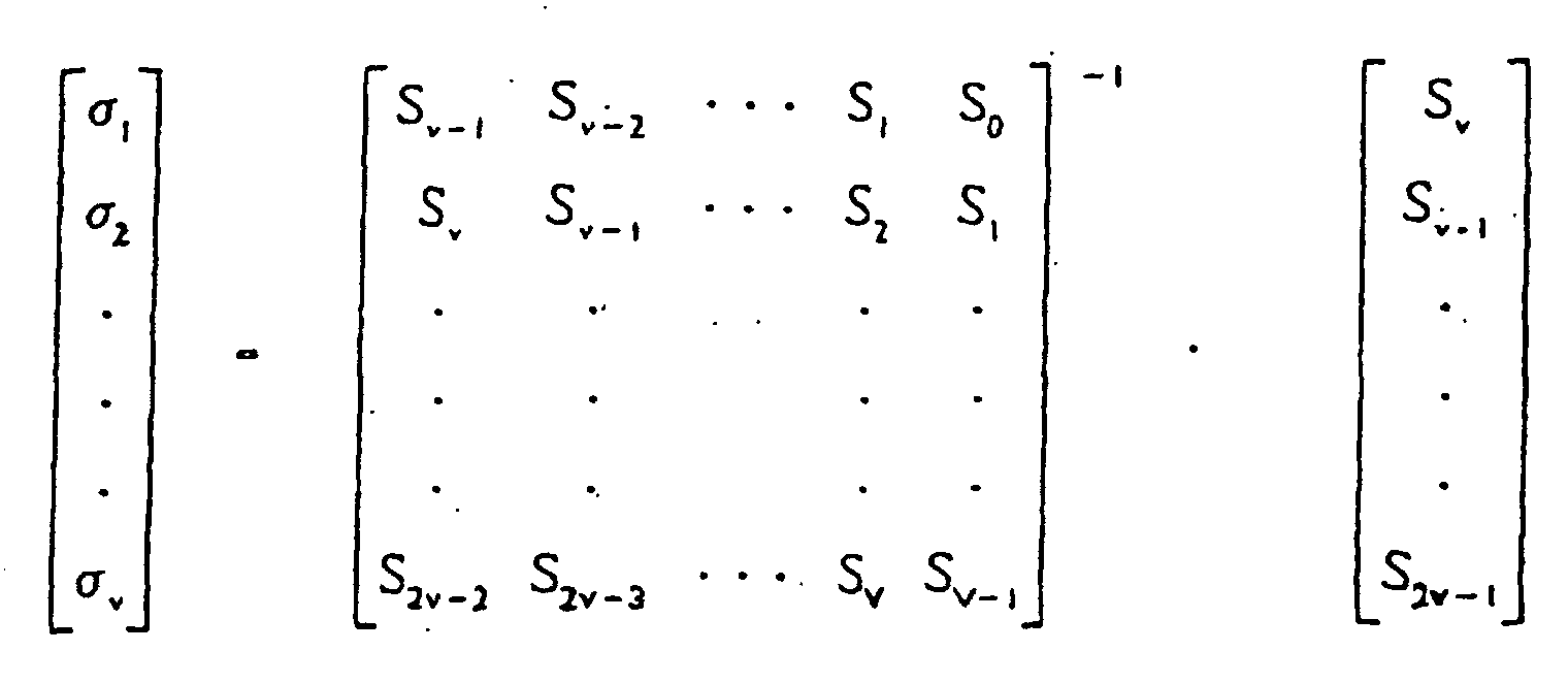 Produzieren eines Index ausgehend von den Koeffizienten (σ1, σ2, ... σx);Herauslesen virtueller Wurzeln von einem spezifischen Speicher unter Verwendung des Index;Transformieren der virtuellen Wurzetn in Fehlerstellen (xj1, xj2 ..., xjv) ausgehend von einer spezifischen Beziehung;Produzieren von Fehlerwerten nach der folgenden Gleichungworin j eine natürliche Zahl kleiner oder gleich v ist; der Wert Ω(x) die Gleichung erfüllt
 Transformieren der Daten in Fehlerkorrekturdaten ausgehend von den Fehlerstellen und Fehlerwerten.
 - Verfahren zur Mehrfehlerkorrektur nach Anspruch 21, worin der Wert t drei beträgt.
- Verfahren zur Mehrfehlerkorrektur nach Anspruch 22, worin der Schritt zum Produzieren eines Index vorgesehen ist zum Produzieren des Index
k1 σ1 2 + σ2 darstellt und k2σ1σ2 + σ3 darstellt. - Verfahren zur Mehrfehlerkorrektur nach einem der Ansprüche 21 bis 23, worin der Schritt zum Transformieren der virtuellen Wurzeln (Z1, Z2 und Z3) in Fehlerstellen (xj1, xj2 ..., xj3) durchgeführt wird gemäß
- Verfahren zur Mehrfehlerkorrektur nach einem der Ansprüche 21 bis 24, worin die in dem spezifischen Speicher gespeicherten virtuellen Wurzeln Wurzelwerte von
Applications Claiming Priority (2)
| Application Number | Priority Date | Filing Date | Title |
|---|---|---|---|
| KR9218409 | 1992-10-07 | ||
| KR1019920018409A KR950002304B1 (ko) | 1992-10-07 | 1992-10-07 | 다중 오류정정 방법 |
Publications (3)
| Publication Number | Publication Date |
|---|---|
| EP0592229A2 EP0592229A2 (de) | 1994-04-13 |
| EP0592229A3 EP0592229A3 (de) | 1995-06-14 |
| EP0592229B1 true EP0592229B1 (de) | 2002-12-11 |
Family
ID=19340772
Family Applications (1)
| Application Number | Title | Priority Date | Filing Date |
|---|---|---|---|
| EP93308005A Expired - Lifetime EP0592229B1 (de) | 1992-10-07 | 1993-10-07 | Verfahren zur Mehrfehlerkorrektur |
Country Status (5)
| Country | Link |
|---|---|
| US (1) | US5450421A (de) |
| EP (1) | EP0592229B1 (de) |
| JP (1) | JPH06208767A (de) |
| KR (1) | KR950002304B1 (de) |
| DE (1) | DE69332556T2 (de) |
Families Citing this family (21)
| Publication number | Priority date | Publication date | Assignee | Title |
|---|---|---|---|---|
| CA2190985C (en) * | 1995-04-12 | 2000-11-28 | Tadashi Kojima | Method and apparatus for generating, recording and transmitting an errorproduct code block having an improved check code arrangement |
| TW311189B (en) * | 1996-09-30 | 1997-07-21 | United Microelectronics Corp | The error-corrected decoding method and its apparatus for Reed-Soloman code |
| NL1006174C2 (nl) * | 1997-04-17 | 1998-12-01 | United Microelectronics Corp | Foutdecoderingswerkwijze alsmede apparaat voor het decoderen. |
| JP3502559B2 (ja) * | 1999-02-05 | 2004-03-02 | 松下電器産業株式会社 | 消失訂正方法、及び消失訂正回路 |
| US6625774B1 (en) * | 1999-10-29 | 2003-09-23 | Stmicroelectronics, Inc. | Redundancy system and method for locating errors in interleaved code words |
| KR100378181B1 (ko) * | 2000-06-09 | 2003-03-29 | 삼성전자주식회사 | Efm/efm+ 디코딩에 의해 검출된 에러위치를 이용한c1/pi 워드의 에러정정 방법 및 장치 |
| FR2817418B1 (fr) * | 2000-11-27 | 2003-02-21 | Matra Nortel Communications | Procede de decodage d'un bloc de symboles et dispositif mettant en oeuvre un tel procede |
| US6748567B1 (en) * | 2001-05-01 | 2004-06-08 | Zettacom, Inc. | Method and system for error correction over serial link |
| US7389463B2 (en) * | 2001-05-29 | 2008-06-17 | Thomson Licensing | Hierarchical block coding for a packet-based communications system |
| US20030061558A1 (en) * | 2001-09-25 | 2003-03-27 | Fackenthal Richard E. | Double error correcting code system |
| US7243296B2 (en) * | 2002-06-21 | 2007-07-10 | Thomson Licensing | Method of forward error correction |
| JP3850433B2 (ja) * | 2003-06-02 | 2006-11-29 | 松下電器産業株式会社 | インタリーブデータに対する誤り訂正方法および装置 |
| KR100519771B1 (ko) * | 2003-07-10 | 2005-10-07 | 삼성전자주식회사 | 에러 정정 디코딩 방법 및 그 장치 |
| FR2861517B1 (fr) * | 2003-10-23 | 2006-01-27 | Thomson Licensing Sa | Methode de reconstruction de paquets perdus et appareils implementant la methode |
| US7543218B2 (en) * | 2004-01-31 | 2009-06-02 | Samsung Electronics Co., Ltd. | DVD decoding method and apparatus using selective po-correction |
| US7328395B1 (en) | 2004-04-13 | 2008-02-05 | Marvell International Ltd. | Iterative Reed-Solomon error-correction decoding |
| US7454690B1 (en) * | 2004-10-27 | 2008-11-18 | Marvell International Ltd. | Architecture and control of reed-solomon list decoding |
| US7404133B2 (en) * | 2004-12-12 | 2008-07-22 | Hewlett-Packard Development Company, L.P. | Error detection and correction employing modulation symbols satisfying predetermined criteria |
| US20090106624A1 (en) * | 2005-09-01 | 2009-04-23 | Hiroaki Kondo | Error correction method |
| US8621321B2 (en) * | 2010-07-01 | 2013-12-31 | Densbits Technologies Ltd. | System and method for multi-dimensional encoding and decoding |
| US9312886B2 (en) * | 2013-09-20 | 2016-04-12 | Seagate Technology Llc | Storage device with multiple coding redundancies |
Family Cites Families (17)
| Publication number | Priority date | Publication date | Assignee | Title |
|---|---|---|---|---|
| CA1170776A (en) * | 1980-07-18 | 1984-07-10 | Yoichiro Sako | Method of error correction of blocks of data |
| JPS58111539A (ja) * | 1981-12-25 | 1983-07-02 | Sony Corp | エラ−訂正方法 |
| JPS5961332A (ja) * | 1982-09-30 | 1984-04-07 | Nec Corp | 誤り訂正回路 |
| JPS6055564A (ja) * | 1983-09-06 | 1985-03-30 | Toshiba Corp | エラ−訂正回路 |
| US4653051A (en) * | 1983-09-14 | 1987-03-24 | Matsushita Electric Industrial Co., Ltd. | Apparatus for detecting and correcting errors on product codes |
| JPH0812612B2 (ja) * | 1983-10-31 | 1996-02-07 | 株式会社日立製作所 | 誤り訂正方法及び装置 |
| NL8400629A (nl) * | 1984-02-29 | 1985-09-16 | Philips Nv | Snelle decodeur voor reed-solomon-codes, welke mede als encodeur te gebruiken is, alsmede opname/reproduktie-apparaat voorzien van zo een encodeur/decodeur. |
| NL8400630A (nl) * | 1984-02-29 | 1985-09-16 | Philips Nv | Decodeerinrichting voor een stroom van codesymbolen die woordsgewijze beschermd zijn door een dubbele reed-solomon-code met een minimum hamming-afstand van 5 over de codesymbolen en een verbladeringsmechanisme tussen de beide codes, alsmede speler voorzien van zo een decodeerinrichting. |
| JPS6116629A (ja) * | 1984-07-02 | 1986-01-24 | Nec Home Electronics Ltd | リ−ドソロモン符号・復号方式における訂正実行方式 |
| NL8403818A (nl) * | 1984-12-17 | 1986-07-16 | Philips Nv | Werkwijze en inrichting voor het decoderen van door een reed-solomon-code beschermde informatiestroom. |
| JPS62246180A (ja) * | 1986-04-18 | 1987-10-27 | Olympus Optical Co Ltd | 誤り訂正方式 |
| US4875211A (en) * | 1986-12-10 | 1989-10-17 | Matsushita Electric Industrial Co., Ltd. | Galois field arithmetic logic unit |
| JP2605269B2 (ja) * | 1987-02-06 | 1997-04-30 | ソニー株式会社 | エラー訂正方法 |
| JPS63193723A (ja) * | 1987-02-06 | 1988-08-11 | Sony Corp | リ−ドソロモン符号の復号方法 |
| AU622626B2 (en) * | 1987-06-03 | 1992-04-16 | Sony Corporation | Method of processing data |
| US4821268A (en) * | 1987-10-26 | 1989-04-11 | Cyclotomics, Inc. | Soft decision Reed-Solomon decoder |
| US4890286A (en) * | 1987-12-11 | 1989-12-26 | Sanyo Electric Co., Ltd. | Method and apparatus for decoding error correcting code |
-
1992
- 1992-10-07 KR KR1019920018409A patent/KR950002304B1/ko not_active Expired - Fee Related
-
1993
- 1993-10-07 JP JP5251988A patent/JPH06208767A/ja active Pending
- 1993-10-07 DE DE69332556T patent/DE69332556T2/de not_active Expired - Fee Related
- 1993-10-07 EP EP93308005A patent/EP0592229B1/de not_active Expired - Lifetime
- 1993-10-07 US US08/133,230 patent/US5450421A/en not_active Expired - Lifetime
Also Published As
| Publication number | Publication date |
|---|---|
| KR940010545A (ko) | 1994-05-26 |
| DE69332556D1 (de) | 2003-01-23 |
| EP0592229A2 (de) | 1994-04-13 |
| EP0592229A3 (de) | 1995-06-14 |
| DE69332556T2 (de) | 2003-11-20 |
| KR950002304B1 (ko) | 1995-03-16 |
| JPH06208767A (ja) | 1994-07-26 |
| US5450421A (en) | 1995-09-12 |
Similar Documents
| Publication | Publication Date | Title |
|---|---|---|
| EP0592229B1 (de) | Verfahren zur Mehrfehlerkorrektur | |
| JP4194850B2 (ja) | 部分的に演繹的に分かる情報の符号化及び復号 | |
| US6963296B2 (en) | Recording method, recording apparatus, transmitting apparatus, reproducing method, reproducing apparatus, receiving apparatus, recording medium, and transmission medium | |
| JPH10256921A (ja) | ディジタルデータの変調及び復調方法並びにディジタルデータの変調及び復調装置 | |
| JPH0152940B2 (de) | ||
| US5408477A (en) | Error correction method | |
| EP1182785A2 (de) | Datenverarbeitungsverfahren und Gerät, Datenaufzeichnungsmedium, Wiedergabeverfahren und Gerät welcher dieses Verfahren anwendet | |
| JP3071828B2 (ja) | 誤り訂正積符号ブロックを生成するためのデータ処理方法と該データを記録媒体に記録するためのデータ処理方法及び該データの処理装置 | |
| JP4290881B2 (ja) | エラー訂正コードを含む磁気媒体上へのデータの格納のための方法及び装置 | |
| WO2003017499A2 (en) | Enhanced coding for informed decoders | |
| JP3764453B2 (ja) | エラー訂正のための符号化装置及び方法と復号化装置及び方法 | |
| JP2004507030A (ja) | ビットストリームを記憶又は復号化する方法 | |
| JP2004532571A (ja) | 情報ワードを符号化する方法と装置、情報ワードを復号する方法と装置、記憶媒体および信号 | |
| EP0354065A2 (de) | Schaltkreis und Methode zum Modulieren digitaler Daten und Schaltkreis zum Demodulieren digitaler Daten | |
| US5574448A (en) | Method and apparatus for encoding data with variable block lengths | |
| JP3768149B2 (ja) | 光記録媒体、データ記録装置及びデータ記録方法 | |
| US7159165B2 (en) | Optical recording medium, data recording or reproducing apparatus and data recording or reproducing method used by the data recording or reproducing apparatus | |
| US20060218464A1 (en) | Optical information recording medium and data recording apparatus thereon | |
| JP2000187948A (ja) | 誤り訂正符号化/復号化方式及び誤り訂正符号化/復号化装置 | |
| EP1251510B1 (de) | Optisches Informationsaufzeichnungsmedium und Datenaufzeichnungsgerät | |
| JP2003242720A (ja) | ディジタルデータ記録再生方法 | |
| JPS63298776A (ja) | エラ−訂正処理方式 | |
| Hu et al. | A New Data Format and a New Error Control Scheme for Optical-Storage Systems | |
| JP2009064554A (ja) | エラー訂正コードを含む磁気媒体上へのデータの格納のための方法及び装置 | |
| JPH06120844A (ja) | 誤り信号訂正装置 |
Legal Events
| Date | Code | Title | Description |
|---|---|---|---|
| PUAI | Public reference made under article 153(3) epc to a published international application that has entered the european phase |
Free format text: ORIGINAL CODE: 0009012 |
|
| AK | Designated contracting states |
Kind code of ref document: A2 Designated state(s): DE FR GB NL |
|
| PUAL | Search report despatched |
Free format text: ORIGINAL CODE: 0009013 |
|
| AK | Designated contracting states |
Kind code of ref document: A3 Designated state(s): DE FR GB NL |
|
| 17P | Request for examination filed |
Effective date: 19951130 |
|
| 17Q | First examination report despatched |
Effective date: 19970616 |
|
| GRAG | Despatch of communication of intention to grant |
Free format text: ORIGINAL CODE: EPIDOS AGRA |
|
| GRAG | Despatch of communication of intention to grant |
Free format text: ORIGINAL CODE: EPIDOS AGRA |
|
| GRAH | Despatch of communication of intention to grant a patent |
Free format text: ORIGINAL CODE: EPIDOS IGRA |
|
| GRAH | Despatch of communication of intention to grant a patent |
Free format text: ORIGINAL CODE: EPIDOS IGRA |
|
| GRAA | (expected) grant |
Free format text: ORIGINAL CODE: 0009210 |
|
| AK | Designated contracting states |
Kind code of ref document: B1 Designated state(s): DE FR GB NL |
|
| REG | Reference to a national code |
Ref country code: GB Ref legal event code: FG4D |
|
| REF | Corresponds to: |
Ref document number: 69332556 Country of ref document: DE Date of ref document: 20030123 |
|
| ET | Fr: translation filed | ||
| PLBE | No opposition filed within time limit |
Free format text: ORIGINAL CODE: 0009261 |
|
| 26N | No opposition filed |
Effective date: 20030912 |
|
| PGFP | Annual fee paid to national office [announced via postgrant information from national office to epo] |
Ref country code: NL Payment date: 20071003 Year of fee payment: 15 Ref country code: DE Payment date: 20071004 Year of fee payment: 15 |
|
| PGFP | Annual fee paid to national office [announced via postgrant information from national office to epo] |
Ref country code: GB Payment date: 20071003 Year of fee payment: 15 Ref country code: FR Payment date: 20071009 Year of fee payment: 15 |
|
| GBPC | Gb: european patent ceased through non-payment of renewal fee |
Effective date: 20081007 |
|
| NLV4 | Nl: lapsed or anulled due to non-payment of the annual fee |
Effective date: 20090501 |
|
| REG | Reference to a national code |
Ref country code: FR Ref legal event code: ST Effective date: 20090630 |
|
| PG25 | Lapsed in a contracting state [announced via postgrant information from national office to epo] |
Ref country code: NL Free format text: LAPSE BECAUSE OF NON-PAYMENT OF DUE FEES Effective date: 20090501 |
|
| PG25 | Lapsed in a contracting state [announced via postgrant information from national office to epo] |
Ref country code: DE Free format text: LAPSE BECAUSE OF NON-PAYMENT OF DUE FEES Effective date: 20090501 |
|
| PG25 | Lapsed in a contracting state [announced via postgrant information from national office to epo] |
Ref country code: FR Free format text: LAPSE BECAUSE OF NON-PAYMENT OF DUE FEES Effective date: 20081031 |
|
| PG25 | Lapsed in a contracting state [announced via postgrant information from national office to epo] |
Ref country code: GB Free format text: LAPSE BECAUSE OF NON-PAYMENT OF DUE FEES Effective date: 20081007 |