EP0592234A1 - Véhicule de manutention - Google Patents
Véhicule de manutention Download PDFInfo
- Publication number
- EP0592234A1 EP0592234A1 EP93308015A EP93308015A EP0592234A1 EP 0592234 A1 EP0592234 A1 EP 0592234A1 EP 93308015 A EP93308015 A EP 93308015A EP 93308015 A EP93308015 A EP 93308015A EP 0592234 A1 EP0592234 A1 EP 0592234A1
- Authority
- EP
- European Patent Office
- Prior art keywords
- load
- vehicle
- carriage
- handling
- mast
- Prior art date
- Legal status (The legal status is an assumption and is not a legal conclusion. Google has not performed a legal analysis and makes no representation as to the accuracy of the status listed.)
- Granted
Links
Images


Classifications
-
- B—PERFORMING OPERATIONS; TRANSPORTING
- B66—HOISTING; LIFTING; HAULING
- B66F—HOISTING, LIFTING, HAULING OR PUSHING, NOT OTHERWISE PROVIDED FOR, e.g. DEVICES WHICH APPLY A LIFTING OR PUSHING FORCE DIRECTLY TO THE SURFACE OF A LOAD
- B66F9/00—Devices for lifting or lowering bulky or heavy goods for loading or unloading purposes
- B66F9/06—Devices for lifting or lowering bulky or heavy goods for loading or unloading purposes movable, with their loads, on wheels or the like, e.g. fork-lift trucks
- B66F9/075—Constructional features or details
- B66F9/08—Masts; Guides; Chains
- B66F9/082—Masts; Guides; Chains inclinable
-
- B—PERFORMING OPERATIONS; TRANSPORTING
- B66—HOISTING; LIFTING; HAULING
- B66F—HOISTING, LIFTING, HAULING OR PUSHING, NOT OTHERWISE PROVIDED FOR, e.g. DEVICES WHICH APPLY A LIFTING OR PUSHING FORCE DIRECTLY TO THE SURFACE OF A LOAD
- B66F9/00—Devices for lifting or lowering bulky or heavy goods for loading or unloading purposes
- B66F9/06—Devices for lifting or lowering bulky or heavy goods for loading or unloading purposes movable, with their loads, on wheels or the like, e.g. fork-lift trucks
- B66F9/075—Constructional features or details
- B66F9/12—Platforms; Forks; Other load supporting or gripping members
- B66F9/18—Load gripping or retaining means
- B66F9/186—Container lifting frames
Definitions
- This invention relates to load handling vehicles of the kind comprising a lifting mast and a lifting carriage moveable up and down the mast, the lifting carriage having mounted thereon load-engaging means.
- Load handling vehicles of this kind especially those which are designed to pick up and carry a load in front of the vehicle (so-called “front loaders”), generally have the lifting mast located close to but in front of the front axle of the vehicle.
- the mast usually comprises two or more telescopic sections to increase the lifting height.
- One common vehicle of this kind is a container-handling vehicle in which the load-engaging means mounted on the carriage comprises a frame having locks for engaging the uppermost corner fittings of a freight container.
- Locating the mast in front of and below the front axle line is necessary to simplify mounting of the carriage and to enable the load-engaging means to pick up loads from ground level.
- the load is carried in front of the vertical plane containing the front axle line, creating a moment about the front wheels which must be compensated by the vehicle's counter-weight.
- One advantage of such an arrangement is that lateral stability of the vehicle is improved by carrying the load in front of the front axle, and while this is important for a lift truck with a narrow track, this is not such an important factor with large trucks with wide front tracks, such as container-handling vehicles, which are quite stable laterally. With these vehicles, fore-and-aft stability is more important, especially in the travelling position with a load at the top of the extended mast. It will be appreciated that fore-and-aft stability is adversely affected where the load is carried in front of the front axle.
- the present invention provides a load-handling vehicle having means for suspending a load in which the mast is located in a more rearward position than previously by providing means for shifting the suspended load rearwardly once it has been lifted to clear the front wheels, to a point where it is suspended over the wheels.
- a load handling vehicle of the kind comprising a chassis, front and rear wheels, a load lifting mast mounted in the chassis with its axis substantially coincident with or behind the plane containing the front axle of the vehicle, a carriage moveable up and down the mast, and a load engaging means adapted to suspend a load therefrom connected to the carriage; wherein the load engaging means is moveable relative to the carriage and drive means are provided operable to move the load engaging means longitudinally of the chassis between a load pick-up and set down position in which the load engaging means is disposed forwardly of the front wheels and a retracted travelling position in which the load engaging means is disposed rearwardly of the load pick-up and set down position and extends at least partially over the front wheels.
- the preferred mechanism for the drive means comprises one or more hydraulic jacks mounted between the load-engaging means and the carriage.
- the carriage incorporates a gantry and the load engaging means comprises a lifting frame freely suspended from the gantry by rods or chains, and the hydraulic jacks are mounted to move the lifting frame outwardly or inwardly relative to the gantry between the handling position and the travelling position on operation thereof.
- the hydraulic jacks are mounted to move the lifting frame outwardly or inwardly relative to the gantry between the handling position and the travelling position on operation thereof.
- other forms of load-engaging frames and drive means can be employed.
- Suitable mechanical, electrical or hydraulic sensing means are provided to prevent the carriage being moved downwardly of the mast when a load is being carried in the travelling position into a position in which the load fouls the front wheels. These ensure that the load can be dropped to a point below the level of the front tyres only when the hydraulic jacks have been operated to move the lifting frame forwardly of the gantry out of the travelling position and into the handling position. Similar sensing means are provided to prevent retraction of the jacks on pick-up of a load until the carriage has been lifted such that the load clears the front wheels. These sensing means can be interlocks or warning devices.
- Fig. 1 shows a known arrangement in which a lifting mast 50 is mounted at its lower end to the chassis 51 of the vehicle by means of a bracket 52 and pin 53.
- Pin 53 is aligned with the front axle 54 which supports wheel 55, but as will be seen in the drawing, the vertical axis 56 of the mast 50 is spaced by a distance x from the front axle line 57. Since the weight of the mast assembly can be substantial, e.g. 12-16 tons, this in itself creates a substantial moment about the front wheel 55. This moment is increased by the presence of a load on the lifting carriage.
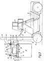
- Fig. 2 shows the mounting arrangement according to the invention.
- mast 60 is mounted on pin 61 disposed immediately above and in the vertical plane containing the front axle line 62.
- Wheel 63 thus carries the weight of the mast 60 directly and no counterbalancing is necessary to compensate for the weight of the mast.
- Fig. 3 shows a front-loading container handling vehicle having a chassis 10, front wheels 11, rear wheels 12, and operators cab 13.
- a lifting mast assembly 14 is disposed substantially over the front axle line 15 of the vehicle.
- This mast assembly 14 is of conventional construction, being telescopic to provide maximum lifting height and being extended by a pair of hydraulic lift jacks which are not shown in the drawing.
- the mast assembly 14 is pivotally mounted at its lower end to the chassis e.g. as shown in Fig. 2 and can be tilted through a small angle by a pair of hydraulic tilt jacks, one shown 17, connected between the mast assembly 14 and the support 18 for the operator's cab 13.
- a carriage 20 is adapted to move up and down the mast, on extension and retraction of the lift jacks by means of reeving chains, also in conventional manner.
- Carriage 20 has mounted thereon gantry 21.
- Gantry 21 is provided with channel section supports 22,23 at each corner thereof within which are mounted spherical bearings 24,25. These bearings receive matching spherical fittings provided on upper ends of suspension rods 26,27, which are suspended from each corner of the gantry.
- the lower ends of suspension rods 26,27 are provided with identical spherical fittings received in matching spherical bearings 28,29 mounted in upper frame member 32 of load-engaging lifting frame 30.
- the lifting frame -30 is thereby suspended by the suspension rods 26,27 from the gantry 21 and the spherical bearings permit free swinging movement of the frame relative to the gantry. Chains or cables may be used to suspend frame 30 as an alternative to the suspension rods.
- Load-engaging lifting frame 30 comprises a lower frame member 34, upper frame member 32 mounted on the lower frame member, and housing 35 mounted on the upper frame member.
- the frame is designed to be engageable with a standard container 31 by means of twistlocks 33 located at each corner of lower frame member 34.
- twistlocks 33 located at each corner of lower frame member 34.
- the vehicle is driven up to a container 31 and the carriage and mast assembly lowered such that the lifting frame 30 rests on top of the container 31 with the twistlocks 33 disposed within the corner fittings of the container.
- the twistlock 33 are then operated to engage the container, and the container can then be lifted by causing carriage 20 to move up the mast by operation of the lift cylinders.
- the vehicle can be driven to its new position where the container 31 is lowered in the reverse of the lifting sequence.
- a fully loaded container imposes substantial loads on the lifting mechanism of a front loading vehicle and since the load is carried in front of the vehicle at all times, usually in a fully raised position to improve visibility for the driver, a loaded vehicle may have a reduced safety factor. This imposes certain limitations on the size of the load and the maneouverability of the truck when it is carrying a container.
- the invention provides for repositioning of the load after lifting into a more stable position permitted by the location of the mast above the front axle.
- a pair of hydraulic jacks are provided to perform a significant outward and inward reaching movement of the lifting frame.
- Jacks 40 each have one end 41 pivotally mounted to the gantry 21, and the other end connected to an attachment point 43 on housing 35 of lifting frame 30. Jacks 40 can be retracted and extended in order to shift the position of lifting frame 30 relative to the mast outwardly and inwardly about rods 26,27 in a direction longitudinally of the vehicle. The extent of this movement is shown by the broken lines in the drawing which represent the limits of angular displacement of the suspension rods 26,27. This enables a container 31 to be picked up from a rest position in the normal way, and then by retraction of the jacks 40, moved rearwardly into a travelling mode in which the container is suspended over the front wheels 11. This brings the load centre closer to the vertical centre of gravity of the truck and improves stability while travelling.
- the mast 16 can be located in the desired position in the chassis since the truck can be made to "reach" for containers in the normal lift position.
- positions 'A' containers can be picked up and lowered and during these operations a standard freight container 31 will clear the front wheels 11.
- the hydraulic jacks 40 are retracted to pull the load 31 inwardly, such that the load and the rear part of frame 30 are disposed substantially over the front wheels 11.
- This position, position 'B' provides much greater stability for travelling than the unretracted position A equivalent to the travelling position of conventional front-loading lift trucks, and substantially reduces the axle load.
- an interlock mechanism is provided to prevent the carriage from being lowered beyond a point at which the container fouls the front wheels.
- This interlock mechanism comprises a mechanical, electrical, hydraulic or similar sensor which is connected to the lifting mechanism.
- a sensor may also be provided to prevent retraction of the jacks 40 when a container has been picked up until the carriage 20 has been raised sufficiently to enable the container to clear the front wheels of the vehicle.
- a warning device such as a bell or a light may be provided for the driver so that this function can be performed manually.
- jacks 40 may be operable independently to cause an angular movement (slew) of the lifting frame 30 relative to the vehicle.
- Fig. 4 shows a "piggy-back" and container handling vehicle 70 fitted with a telescopic mast assembly 71 with its vertical axis disposed directly over the front wheels 72.
- the carriage 73 supports inverted forks 74 on which is slidably mounted a "piggy-back" and intermodal attachment 75 for loads such as swap bodies and semi-trailers.
- Attachment 75 is slidable outwardly along forks 74 from the position shown in the drawings by means of a pair of hydraulic cylinders (one shown in broken lines at 76) into a load pick-up position, and can be retracted into the travelling position shown in the drawing by the same cylinders.
- Fig. 5 shows diagramatically the effect of this arrangement on the vertical centre of gravity of the truck.
- the load pick-up position of a container is shown in full lines 80, the load centre of the container being shown at a .
- the vertical centre of gravity of the truck is located at a '.
- the load centre lies at b and the vertical centre of gravity of the truck moves rearwardly to b '.
- the front axle line of the truck is shown at 81, coinciding with the vertical axis 82 of mast 83.
- the front and rear wheels are denoted by 84 and 85 respectively.
Landscapes
- Engineering & Computer Science (AREA)
- Transportation (AREA)
- Structural Engineering (AREA)
- Civil Engineering (AREA)
- Life Sciences & Earth Sciences (AREA)
- Geology (AREA)
- Mechanical Engineering (AREA)
- Forklifts And Lifting Vehicles (AREA)
- Loading Or Unloading Of Vehicles (AREA)
Applications Claiming Priority (2)
| Application Number | Priority Date | Filing Date | Title |
|---|---|---|---|
| GB9221262 | 1992-10-09 | ||
| GB9221262A GB2271335B (en) | 1992-10-09 | 1992-10-09 | Improvements in load handling vehicles |
Publications (2)
| Publication Number | Publication Date |
|---|---|
| EP0592234A1 true EP0592234A1 (fr) | 1994-04-13 |
| EP0592234B1 EP0592234B1 (fr) | 1998-07-01 |
Family
ID=10723221
Family Applications (1)
| Application Number | Title | Priority Date | Filing Date |
|---|---|---|---|
| EP19930308015 Expired - Lifetime EP0592234B1 (fr) | 1992-10-09 | 1993-10-08 | Véhicule de manutention |
Country Status (4)
| Country | Link |
|---|---|
| EP (1) | EP0592234B1 (fr) |
| DE (1) | DE69319398T2 (fr) |
| ES (1) | ES2118905T3 (fr) |
| GB (1) | GB2271335B (fr) |
Cited By (2)
| Publication number | Priority date | Publication date | Assignee | Title |
|---|---|---|---|---|
| EP1129982A3 (fr) * | 2000-03-03 | 2003-12-03 | SMV Lifttrucks AB | Dispositif à des chariots élévateurs à contrepoids |
| WO2012114166A3 (fr) * | 2011-02-25 | 2012-11-08 | B-P Battioni E Pagani S.P.A. | Équipement de mise en prise et de libération d'une charge |
Families Citing this family (3)
| Publication number | Priority date | Publication date | Assignee | Title |
|---|---|---|---|---|
| AU2003202458B2 (en) * | 2003-03-26 | 2005-11-24 | Philip Lloyd Truswell | Waste Bin Transportation Aid |
| CN110589691A (zh) * | 2019-10-11 | 2019-12-20 | 徐州市凯诺机械有限公司 | 一种港口灵活移动的起吊车 |
| CN112338800A (zh) * | 2020-11-07 | 2021-02-09 | 台州聚合科技有限公司 | 一种用于橡胶轮胎生产的机械夹具 |
Citations (7)
| Publication number | Priority date | Publication date | Assignee | Title |
|---|---|---|---|---|
| US2220450A (en) * | 1938-11-22 | 1940-11-05 | Roy C Howell | Industrial truck |
| DE2044410A1 (de) * | 1969-09-02 | 1971-04-29 | Lancer Boss Ltd , Leighton Buzzard, Bedfordshire (Großbritannien) | Hebevorrichtung |
| US3633777A (en) * | 1970-10-26 | 1972-01-11 | Taylor Machine Works | Cargo container handling assembly |
| GB1423513A (en) * | 1972-02-02 | 1976-02-04 | Lancer Boss Group Ltd | Load lifting attachments |
| DE3300018A1 (de) * | 1983-01-03 | 1984-07-12 | Hans Ing.(grad.) 8761 Weilbach Rieschel | Frontstapler |
| WO1985001995A1 (fr) * | 1983-11-04 | 1985-05-09 | Towmotor Corporation | Systeme actionne par fluide |
| DE8005631U1 (de) * | 1980-03-01 | 1989-12-28 | Kaup GmbH & Co KG Gesellschaft für Maschinenbau, 8750 Aschaffenburg | Containertraggerät für einen Hublader |
Family Cites Families (6)
| Publication number | Priority date | Publication date | Assignee | Title |
|---|---|---|---|---|
| US2975923A (en) * | 1958-10-13 | 1961-03-21 | Yale & Towne Mfg Co | Swinging and extending forks |
| GB966227A (en) * | 1960-11-28 | 1964-08-06 | Raymond Corp | Load handling truck |
| US4395190A (en) * | 1981-03-03 | 1983-06-26 | Spyder Sales & Service, Inc. | Power operated extensions for forks of a fork lift truck |
| US4983094A (en) * | 1986-07-18 | 1991-01-08 | Caterpillar Industrial Inc. | Load lifting attachment |
| SE458856B (sv) * | 1987-02-24 | 1989-05-16 | Semax Truck Ab | Anordning vid gaffeltruck med bakom foerarhytten anordnad lyftmast |
| US5026245A (en) * | 1989-06-29 | 1991-06-25 | Caterpillar Industrial Inc. | Clamping arrangement for a lift mast |
-
1992
- 1992-10-09 GB GB9221262A patent/GB2271335B/en not_active Expired - Fee Related
-
1993
- 1993-10-08 EP EP19930308015 patent/EP0592234B1/fr not_active Expired - Lifetime
- 1993-10-08 ES ES93308015T patent/ES2118905T3/es not_active Expired - Lifetime
- 1993-10-08 DE DE1993619398 patent/DE69319398T2/de not_active Expired - Fee Related
Patent Citations (7)
| Publication number | Priority date | Publication date | Assignee | Title |
|---|---|---|---|---|
| US2220450A (en) * | 1938-11-22 | 1940-11-05 | Roy C Howell | Industrial truck |
| DE2044410A1 (de) * | 1969-09-02 | 1971-04-29 | Lancer Boss Ltd , Leighton Buzzard, Bedfordshire (Großbritannien) | Hebevorrichtung |
| US3633777A (en) * | 1970-10-26 | 1972-01-11 | Taylor Machine Works | Cargo container handling assembly |
| GB1423513A (en) * | 1972-02-02 | 1976-02-04 | Lancer Boss Group Ltd | Load lifting attachments |
| DE8005631U1 (de) * | 1980-03-01 | 1989-12-28 | Kaup GmbH & Co KG Gesellschaft für Maschinenbau, 8750 Aschaffenburg | Containertraggerät für einen Hublader |
| DE3300018A1 (de) * | 1983-01-03 | 1984-07-12 | Hans Ing.(grad.) 8761 Weilbach Rieschel | Frontstapler |
| WO1985001995A1 (fr) * | 1983-11-04 | 1985-05-09 | Towmotor Corporation | Systeme actionne par fluide |
Cited By (2)
| Publication number | Priority date | Publication date | Assignee | Title |
|---|---|---|---|---|
| EP1129982A3 (fr) * | 2000-03-03 | 2003-12-03 | SMV Lifttrucks AB | Dispositif à des chariots élévateurs à contrepoids |
| WO2012114166A3 (fr) * | 2011-02-25 | 2012-11-08 | B-P Battioni E Pagani S.P.A. | Équipement de mise en prise et de libération d'une charge |
Also Published As
| Publication number | Publication date |
|---|---|
| ES2118905T3 (es) | 1998-10-01 |
| GB2271335B (en) | 1996-06-26 |
| DE69319398T2 (de) | 1999-04-22 |
| GB2271335A (en) | 1994-04-13 |
| GB9221262D0 (en) | 1992-11-25 |
| DE69319398D1 (de) | 1998-08-06 |
| EP0592234B1 (fr) | 1998-07-01 |
Similar Documents
| Publication | Publication Date | Title |
|---|---|---|
| US3747789A (en) | Load handling vehicle | |
| US4948326A (en) | Load lifting attachment mounted on a truck frame | |
| US4943203A (en) | Retriever truck | |
| AU730199B2 (en) | Container handling systems | |
| US3441158A (en) | Vehicle with fifth wheel and load lifting and carrying apparatus | |
| US6669433B1 (en) | Device for handling containers for road transport | |
| WO1996031430B1 (fr) | Mecanisme pour le chargement et le dechargement de conteneurs transportes par camion | |
| US4274795A (en) | Load carrying vehicles | |
| US4327945A (en) | High lift, side dumping vehicle | |
| EP0592234B1 (fr) | Véhicule de manutention | |
| US3543957A (en) | Fork lift trucks | |
| EP0027811B1 (fr) | Camion pour le levage et le transport d'un container | |
| US4286915A (en) | Straddle carrier | |
| GB2153339A (en) | Fork lift agricultural trailer | |
| GB2033871A (en) | Improvements in or relating to lifting trucks | |
| US3874528A (en) | Vehicle mounted loader for handling concrete castings | |
| US4576390A (en) | Combination outrigger stabilizer and lift axle for vehicles | |
| US4613276A (en) | Vehicle with load handling apparatus | |
| EP0761589A1 (fr) | Mécanisme de levage pour véhicule routier | |
| GB2206097A (en) | Loading and unloading vehicles | |
| GB2345048A (en) | Lift truck | |
| GB2202497A (en) | Tipping vehicles, and their stabilisation | |
| GB2077697A (en) | Breakdown recovery vehicle | |
| GB1582754A (en) | Loadcarrying vehicles | |
| CN220723406U (zh) | 一种防倾斜随车吊车架 |
Legal Events
| Date | Code | Title | Description |
|---|---|---|---|
| PUAI | Public reference made under article 153(3) epc to a published international application that has entered the european phase |
Free format text: ORIGINAL CODE: 0009012 |
|
| AK | Designated contracting states |
Kind code of ref document: A1 Designated state(s): DE ES FR GB IT NL SE |
|
| 17P | Request for examination filed |
Effective date: 19941011 |
|
| RAP1 | Party data changed (applicant data changed or rights of an application transferred) |
Owner name: BOSS GROUP LIMITED |
|
| RAP3 | Party data changed (applicant data changed or rights of an application transferred) |
Owner name: BOSS GROUP LIMITED |
|
| 17Q | First examination report despatched |
Effective date: 19960604 |
|
| GRAG | Despatch of communication of intention to grant |
Free format text: ORIGINAL CODE: EPIDOS AGRA |
|
| GRAG | Despatch of communication of intention to grant |
Free format text: ORIGINAL CODE: EPIDOS AGRA |
|
| GRAH | Despatch of communication of intention to grant a patent |
Free format text: ORIGINAL CODE: EPIDOS IGRA |
|
| GRAH | Despatch of communication of intention to grant a patent |
Free format text: ORIGINAL CODE: EPIDOS IGRA |
|
| GRAA | (expected) grant |
Free format text: ORIGINAL CODE: 0009210 |
|
| ITF | It: translation for a ep patent filed | ||
| RAP1 | Party data changed (applicant data changed or rights of an application transferred) |
Owner name: BOSS GROUP LIMITED |
|
| AK | Designated contracting states |
Kind code of ref document: B1 Designated state(s): DE ES FR GB IT NL SE |
|
| REF | Corresponds to: |
Ref document number: 69319398 Country of ref document: DE Date of ref document: 19980806 |
|
| ET | Fr: translation filed | ||
| REG | Reference to a national code |
Ref country code: ES Ref legal event code: FG2A Ref document number: 2118905 Country of ref document: ES Kind code of ref document: T3 |
|
| PGFP | Annual fee paid to national office [announced via postgrant information from national office to epo] |
Ref country code: GB Payment date: 19981005 Year of fee payment: 6 |
|
| PLBE | No opposition filed within time limit |
Free format text: ORIGINAL CODE: 0009261 |
|
| 26N | No opposition filed | ||
| PG25 | Lapsed in a contracting state [announced via postgrant information from national office to epo] |
Ref country code: GB Free format text: LAPSE BECAUSE OF NON-PAYMENT OF DUE FEES Effective date: 19991008 |
|
| GBPC | Gb: european patent ceased through non-payment of renewal fee |
Effective date: 19991008 |
|
| PGFP | Annual fee paid to national office [announced via postgrant information from national office to epo] |
Ref country code: ES Payment date: 20011016 Year of fee payment: 9 |
|
| PGFP | Annual fee paid to national office [announced via postgrant information from national office to epo] |
Ref country code: FR Payment date: 20011017 Year of fee payment: 9 |
|
| PGFP | Annual fee paid to national office [announced via postgrant information from national office to epo] |
Ref country code: SE Payment date: 20011019 Year of fee payment: 9 |
|
| PGFP | Annual fee paid to national office [announced via postgrant information from national office to epo] |
Ref country code: NL Payment date: 20011031 Year of fee payment: 9 |
|
| PGFP | Annual fee paid to national office [announced via postgrant information from national office to epo] |
Ref country code: DE Payment date: 20011124 Year of fee payment: 9 |
|
| NLS | Nl: assignments of ep-patents |
Owner name: BOSS UK HOLDING COMPANY LIMITED |
|
| NLT1 | Nl: modifications of names registered in virtue of documents presented to the patent office pursuant to art. 16 a, paragraph 1 |
Owner name: BOSS MANUFACTURING LIMITED |
|
| PG25 | Lapsed in a contracting state [announced via postgrant information from national office to epo] |
Ref country code: SE Free format text: LAPSE BECAUSE OF NON-PAYMENT OF DUE FEES Effective date: 20021009 Ref country code: ES Free format text: LAPSE BECAUSE OF NON-PAYMENT OF DUE FEES Effective date: 20021009 |
|
| PG25 | Lapsed in a contracting state [announced via postgrant information from national office to epo] |
Ref country code: NL Free format text: LAPSE BECAUSE OF NON-PAYMENT OF DUE FEES Effective date: 20030501 Ref country code: DE Free format text: LAPSE BECAUSE OF NON-PAYMENT OF DUE FEES Effective date: 20030501 |
|
| EUG | Se: european patent has lapsed | ||
| PG25 | Lapsed in a contracting state [announced via postgrant information from national office to epo] |
Ref country code: FR Free format text: LAPSE BECAUSE OF NON-PAYMENT OF DUE FEES Effective date: 20030630 |
|
| NLV4 | Nl: lapsed or anulled due to non-payment of the annual fee |
Effective date: 20030501 |
|
| REG | Reference to a national code |
Ref country code: FR Ref legal event code: ST |
|
| REG | Reference to a national code |
Ref country code: ES Ref legal event code: FD2A Effective date: 20031112 |
|
| PG25 | Lapsed in a contracting state [announced via postgrant information from national office to epo] |
Ref country code: IT Free format text: LAPSE BECAUSE OF NON-PAYMENT OF DUE FEES;WARNING: LAPSES OF ITALIAN PATENTS WITH EFFECTIVE DATE BEFORE 2007 MAY HAVE OCCURRED AT ANY TIME BEFORE 2007. THE CORRECT EFFECTIVE DATE MAY BE DIFFERENT FROM THE ONE RECORDED. Effective date: 20051008 |