EP0592266A1 - Stabbefestigungsvorrichtung, insbesondere für Osteosynthese oder Arthrodese - Google Patents
Stabbefestigungsvorrichtung, insbesondere für Osteosynthese oder Arthrodese Download PDFInfo
- Publication number
- EP0592266A1 EP0592266A1 EP93402297A EP93402297A EP0592266A1 EP 0592266 A1 EP0592266 A1 EP 0592266A1 EP 93402297 A EP93402297 A EP 93402297A EP 93402297 A EP93402297 A EP 93402297A EP 0592266 A1 EP0592266 A1 EP 0592266A1
- Authority
- EP
- European Patent Office
- Prior art keywords
- head
- bar
- rod
- connecting element
- jumper
- Prior art date
- Legal status (The legal status is an assumption and is not a legal conclusion. Google has not performed a legal analysis and makes no representation as to the accuracy of the status listed.)
- Ceased
Links
- 208000037873 arthrodesis Diseases 0.000 title claims abstract description 13
- 210000000988 bone and bone Anatomy 0.000 claims description 13
- 230000003100 immobilizing effect Effects 0.000 claims description 9
- 230000000295 complement effect Effects 0.000 claims description 5
- 240000007817 Olea europaea Species 0.000 claims description 2
- 239000013013 elastic material Substances 0.000 claims description 2
- 230000000284 resting effect Effects 0.000 claims 1
- 239000000470 constituent Substances 0.000 description 3
- 240000008042 Zea mays Species 0.000 description 1
- 238000006243 chemical reaction Methods 0.000 description 1
- 230000008878 coupling Effects 0.000 description 1
- 238000010168 coupling process Methods 0.000 description 1
- 238000005859 coupling reaction Methods 0.000 description 1
- 238000010586 diagram Methods 0.000 description 1
- 238000000034 method Methods 0.000 description 1
Images
Classifications
-
- A—HUMAN NECESSITIES
- A61—MEDICAL OR VETERINARY SCIENCE; HYGIENE
- A61B—DIAGNOSIS; SURGERY; IDENTIFICATION
- A61B17/00—Surgical instruments, devices or methods
- A61B17/56—Surgical instruments or methods for treatment of bones or joints; Devices specially adapted therefor
- A61B17/58—Surgical instruments or methods for treatment of bones or joints; Devices specially adapted therefor for osteosynthesis, e.g. bone plates, screws or setting implements
- A61B17/68—Internal fixation devices, including fasteners and spinal fixators, even if a part thereof projects from the skin
- A61B17/70—Spinal positioners or stabilisers, e.g. stabilisers comprising fluid filler in an implant
- A61B17/7001—Screws or hooks combined with longitudinal elements which do not contact vertebrae
- A61B17/7035—Screws or hooks, wherein a rod-clamping part and a bone-anchoring part can pivot relative to each other
- A61B17/704—Screws or hooks, wherein a rod-clamping part and a bone-anchoring part can pivot relative to each other the longitudinal element passing through a ball-joint in the screw head
-
- A—HUMAN NECESSITIES
- A61—MEDICAL OR VETERINARY SCIENCE; HYGIENE
- A61B—DIAGNOSIS; SURGERY; IDENTIFICATION
- A61B17/00—Surgical instruments, devices or methods
- A61B17/56—Surgical instruments or methods for treatment of bones or joints; Devices specially adapted therefor
- A61B17/58—Surgical instruments or methods for treatment of bones or joints; Devices specially adapted therefor for osteosynthesis, e.g. bone plates, screws or setting implements
- A61B17/68—Internal fixation devices, including fasteners and spinal fixators, even if a part thereof projects from the skin
- A61B17/84—Fasteners therefor or fasteners being internal fixation devices
- A61B17/86—Pins or screws or threaded wires; nuts therefor
- A61B17/8695—Washers
-
- A—HUMAN NECESSITIES
- A61—MEDICAL OR VETERINARY SCIENCE; HYGIENE
- A61F—FILTERS IMPLANTABLE INTO BLOOD VESSELS; PROSTHESES; DEVICES PROVIDING PATENCY TO, OR PREVENTING COLLAPSING OF, TUBULAR STRUCTURES OF THE BODY, e.g. STENTS; ORTHOPAEDIC, NURSING OR CONTRACEPTIVE DEVICES; FOMENTATION; TREATMENT OR PROTECTION OF EYES OR EARS; BANDAGES, DRESSINGS OR ABSORBENT PADS; FIRST-AID KITS
- A61F2/00—Filters implantable into blood vessels; Prostheses, i.e. artificial substitutes or replacements for parts of the body; Appliances for connecting them with the body; Devices providing patency to, or preventing collapsing of, tubular structures of the body, e.g. stents
- A61F2/02—Prostheses implantable into the body
- A61F2/30—Joints
- A61F2002/30001—Additional features of subject-matter classified in A61F2/28, A61F2/30 and subgroups thereof
- A61F2002/30316—The prosthesis having different structural features at different locations within the same prosthesis; Connections between prosthetic parts; Special structural features of bone or joint prostheses not otherwise provided for
- A61F2002/30329—Connections or couplings between prosthetic parts, e.g. between modular parts; Connecting elements
- A61F2002/30383—Connections or couplings between prosthetic parts, e.g. between modular parts; Connecting elements made by laterally inserting a protrusion, e.g. a rib into a complementarily-shaped groove
- A61F2002/30387—Dovetail connection
-
- A—HUMAN NECESSITIES
- A61—MEDICAL OR VETERINARY SCIENCE; HYGIENE
- A61F—FILTERS IMPLANTABLE INTO BLOOD VESSELS; PROSTHESES; DEVICES PROVIDING PATENCY TO, OR PREVENTING COLLAPSING OF, TUBULAR STRUCTURES OF THE BODY, e.g. STENTS; ORTHOPAEDIC, NURSING OR CONTRACEPTIVE DEVICES; FOMENTATION; TREATMENT OR PROTECTION OF EYES OR EARS; BANDAGES, DRESSINGS OR ABSORBENT PADS; FIRST-AID KITS
- A61F2220/00—Fixations or connections for prostheses classified in groups A61F2/00 - A61F2/26 or A61F2/82 or A61F9/00 or A61F11/00 or subgroups thereof
- A61F2220/0025—Connections or couplings between prosthetic parts, e.g. between modular parts; Connecting elements
Definitions
- the present invention relates to devices for immobilizing a bar relative to a bone part with a view, for example, to carrying out an osteosynthesis or an arthrodesis, in particular spinal, that is to say the devices which allow, by means at least one bar and fixing means, to make a connection between two bones such as, for example, two vertebrae of a spine.
- Such a device is for example described in Patent DE-A-4,107,480. It essentially comprises a rod and a head with two opposite faces, a rider in the shape of a substantially "U” comprising at least one base and two integral lateral branches from the base at one of their ends, two hooks mounted respectively on the free end of the two lateral branches, laterally to these branches, towards the inside of the "U” and substantially facing one another, and means for exerting a couple of opposite forces between the rider and the head via the bar so as to join together the rider, the head and the bar.
- This known device makes it possible to fix a bar to obtain a spinal arthrodesis, but has the disadvantage of making it very difficult sometimes to align the connecting bar with respect to the vertebrae.
- the present invention thus aims to achieve a device for immobilizing a bar relative to a bone part in order, for example, to perform an osteosynthesis or arthrodesis, in particular spinal, which obviates the drawbacks mentioned above.
- the subject of the present invention is a device for immobilizing a bar with respect to a bone part with a view, for example, to carrying out an osteosynthesis or an arthrodesis, in particular spinal, comprising fixing means, these means comprising a rod and a head with two substantially opposite faces, said rod being integral with one of the two faces of said head and capable of being linked directly or indirectly to said bone part, a rider in the shape of a substantially "U” comprising at least a base and two lateral branches integral with said base, two hooks mounted respectively on the free end of the two lateral branches, said hooks being mounted laterally at the free ends of the two said branches, towards the inside of said "U” and substantially in looking at each other, and means for exerting a couple of opposite forces between said rider and said head by means of said bar so as to join together said rider, said head and said bar, characterized by the fact that the distance separating the two said hooks is less than the width of at least part of said head and greater than the section of said rod and said fixing means
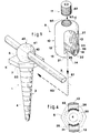
- Figures 1 and 2 show an embodiment of a device 1 for immobilizing a bar 2 for, in particular, osteosynthesis or spinal arthrodesis.
- This device comprises fixing means 3 on a bone part 8, these means comprising a rod 4 and a head 5 with two faces 6, 7 substantially opposite, the section of the head being greater than the section of the rod, the rod 4 is integral with one 7 of the two faces of the head and it is capable of being linked directly or indirectly to the bone part 8, for example by screwing when it is threaded or by any other suitable means.
- the device also comprises means 9 for securing the bar 2 with the head 5.
- These means 9 for securing the bar 2 with the head 5 comprise a jumper 10 substantially in the shape of a "U" comprising at least one base 11 and at least two lateral branches 12, 13 integral with this base 11, hooking means 14 the free end 15, 16 of the two lateral branches 12, 13 of the jumper 10 not secured to the base 11, with the head 5, and means 17 for exerting a couple of opposite forces between the jumper 10 and the head 5 by through the bar 2 so as to secure the jumper 10 together, the head 5 and bar 2.
- the hooking means 14 of the free end 15, 16 of the two lateral branches 12, 13 of the jumper 10 not secured to the base 11, with the head 5, comprise two hooks 21, 22 mounted respectively on the free end 15, 16 of the two lateral branches 12, 13.
- These hooks 21, 22 are mounted laterally at the free ends 15, 16 towards the inside 23 of the "U” and substantially facing one of the other, the distance separating them being less than the width of at least part of the head 5 and greater than the cross section of the rod 4 and of the bar 2, the distance internally separating the two lateral branches 12, 13 and the depth 23 of the "U” being greater than the section of the bar 2, this section being constituted by the diameter of the bar in the most advantageous case where this bar is cylindrical of revolution.
- the head 5 can be introduced between the two branches of the rider before being secured with their free end and so that the rider 10 and the head 5 can at least slightly pivot with respect to each other substantially around the axis of the rod 4, at least part of the head, if not all, has a width, taken in a direction perpendicular to the axis of the rod 4, less than the distance internally separating the two branches side of the rider.
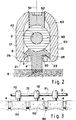
- the hooking means 14 of the free end 15, 16 of the two lateral branches 12, 13 of the jumper 10, with the head 5, further comprise a projecting part 25, 26 on each of the hooks 21, 22, these parts 25, 26 projecting towards the bottom 27 of the "U".
- this head advantageously comprises a hollow groove 30 produced on its face 7 secured to the rod 4 and of a section substantially complementary to that of the projecting parts 25, 26.
- this groove 30 and the projecting parts 25, 26 are defined on two substantially circular lines of the same radius, as shown in FIG. 4, so as to obtain perfect engagement of the projecting parts 25, 26 in the groove 30 whatever the relative angular positions of the head 5 and the jumper 10.
- section of the groove 30 and the projecting parts 25, 26 is advantageously triangular or of a shape which can be assimilated to a triangular shape or the like, in order to obtain an engagement of the conical type. and promote strong coupling and rigid between head 5 and jumper 10.
- the example of the jumper 10 illustrated in particular in FIG. 1 is a preferred embodiment for most cases of use of the device.
- the jumper can be made so that its two lateral branches 12, 13 are interconnected on one of the two faces of the "U” by a wall near the ends 15, 16 not integral with the base 11. It is only necessary that, in this wall, an opening is defined which allows the passage of the bar 2 and the translation of the jumper 10 along its axis 51 so that the hooking means 14 can cooperate with the head 5.
- the means 17 for exerting a couple of opposite forces between the jumper 10 and the head 5 by means of the bar 2 so as to secure the jumper 10 together , the head 5 and the bar 2 comprise a connecting element 40 at least partially surrounding the bar 2 and advantageously deformable.
- this connecting element 40 is located between the two lateral branches 12, 13 of the jumper 10 and rests on the face 6 of the head 5 opposite to the face 7 secured to the rod 4.
- this connecting element 40 has, by its external surface 41, a substantially spherical shape with a diameter slightly less than the distance internally separating the two lateral branches 12, 13 and comprises a diametrical breakthrough 42 of a substantially equal section or slightly larger than the cross section of the bar 2. It can be made, for example, by a split olive and / or made of an elastic material.
- the face 6 of the head opposite to the face 7 secured to the rod 4 comprises a hollow housing 53 complementary to at least a portion of the surface outer 41 substantially spherical of the connecting element 40.
- the means 14 for exerting a couple of opposite forces between the jumper 10 and the head 5 by means of the bar 2 further comprise, for example as illustrated, a threaded orifice 50 passing through the base 11 of the jumper 10 along an axis 51 substantially parallel to the two lateral branches 12, 13 and a threaded nut 52 at the same pitch as the threaded orifice 50, the nut being able to be screwed into this orifice 50 so as to come towards the bar 2 when it is placed between the two branches 12, 13 of the rider and coming into contact with the connecting element 40.
- the face 63 of the nut 52 which comes into contact is spherical concave, complementary to the external surface of the element 40, so that the pressing force exerted by the nut 52 on the connecting element is perfectly distributed over the largest possible surface.
- the rod 4 can be a threaded rod capable of being placed directly by screwing into a part of bone, but that it can also be an indirect connecting rod between two bone parts by means, for example, of two bars which are themselves fixed to these bone parts by any means, in particular by devices according to the invention.
- the rider may have only one base and two lateral branches 12, 13 for immobilizing a bar 2. But it may also have, on the same base 11, three branches making it possible to define two "U" juxtaposed, for example to immobilize two bars together 2.
- the device for immobilizing a bar for osteosynthesis or arthrodesis described above is used in the following manner, described in the case of a spinal arthrodesis schematically represented, FIG. 3, on a vertebral column 60.
- the surgeon begins by placing several rods 4 in the vertebrae 70 by screwing them until their limit sinking defined, for example, by a stop on each rod 4.
- On the bar 2 he puts on as many connecting elements 40 as 'there are heads 5 which emerge from the vertebrae 70 and give the bar the desired shape so that it passes through all the heads 5 and so that the connecting elements 40 can rest in the housings 53 provided for this purpose on their face 6.
- the bar and the connecting elements are then in the position shown on the left-hand side of FIG. 1.
- the surgeon then takes as many jumpers 10 as there are visible heads and places them in cooperation with these heads, as described below. after.
- Each rider is slid over the bar, for example in the space 71 between two heads, so that its two lateral branches frame the bar "on horseback", the latter being positioned in the hollow 23 of the "U” and advantageously pressed against the bottom 27.
- This first movement of each jumper is illustrated by the right-hand portion in dashed lines 61 in FIG. 1. From this position, the jumper is translated along the path illustrated, in FIG. 1, by the right portion in broken lines 62, until the projecting portions 25, 26 engage in the groove 30 of the head with which this rider must be associated.
- the surgeon can then place the nut 52 by screwing it into the threaded orifice 50, until its end 63 comes into contact with the connecting element 40 and presses strongly on it so that, by reaction, it s 'exerts a couple of forces between the rider and the head capable of holding the rider 10, the head 5 and the bar 2 perfectly integral by the connecting element 40.
Landscapes
- Health & Medical Sciences (AREA)
- Orthopedic Medicine & Surgery (AREA)
- Life Sciences & Earth Sciences (AREA)
- Neurology (AREA)
- Surgery (AREA)
- Heart & Thoracic Surgery (AREA)
- Engineering & Computer Science (AREA)
- Biomedical Technology (AREA)
- Nuclear Medicine, Radiotherapy & Molecular Imaging (AREA)
- Medical Informatics (AREA)
- Molecular Biology (AREA)
- Animal Behavior & Ethology (AREA)
- General Health & Medical Sciences (AREA)
- Public Health (AREA)
- Veterinary Medicine (AREA)
- Surgical Instruments (AREA)
Applications Claiming Priority (2)
| Application Number | Priority Date | Filing Date | Title |
|---|---|---|---|
| FR9212312 | 1992-10-07 | ||
| FR9212312A FR2696335B1 (fr) | 1992-10-07 | 1992-10-07 | Dispositif d'immobilisation d'une barre pour, notamment, ostéosynthèse ou arthrodèse. |
Publications (1)
| Publication Number | Publication Date |
|---|---|
| EP0592266A1 true EP0592266A1 (de) | 1994-04-13 |
Family
ID=9434548
Family Applications (1)
| Application Number | Title | Priority Date | Filing Date |
|---|---|---|---|
| EP93402297A Ceased EP0592266A1 (de) | 1992-10-07 | 1993-09-21 | Stabbefestigungsvorrichtung, insbesondere für Osteosynthese oder Arthrodese |
Country Status (2)
| Country | Link |
|---|---|
| EP (1) | EP0592266A1 (de) |
| FR (1) | FR2696335B1 (de) |
Cited By (11)
| Publication number | Priority date | Publication date | Assignee | Title |
|---|---|---|---|---|
| WO2006096306A2 (en) | 2005-03-04 | 2006-09-14 | Depuy Spine Sarl | Constrained motion bone screw assembly |
| US7951175B2 (en) | 2005-03-04 | 2011-05-31 | Depuy Spine, Inc. | Instruments and methods for manipulating a vertebra |
| US7951174B2 (en) | 2005-10-21 | 2011-05-31 | Depuy Spine, Inc. | Adjustable bone screw assembly |
| US8348952B2 (en) | 2006-01-26 | 2013-01-08 | Depuy International Ltd. | System and method for cooling a spinal correction device comprising a shape memory material for corrective spinal surgery |
| US8608746B2 (en) | 2008-03-10 | 2013-12-17 | DePuy Synthes Products, LLC | Derotation instrument with reduction functionality |
| US8709015B2 (en) | 2008-03-10 | 2014-04-29 | DePuy Synthes Products, LLC | Bilateral vertebral body derotation system |
| CN104799931A (zh) * | 2015-04-13 | 2015-07-29 | 李贵涛 | 窝臼轨链式复位固定动态椎弓根螺钉系统 |
| US9101416B2 (en) | 2003-01-24 | 2015-08-11 | DePuy Synthes Products, Inc. | Spinal rod approximator |
| US10973556B2 (en) | 2008-06-17 | 2021-04-13 | DePuy Synthes Products, Inc. | Adjustable implant assembly |
| FR3148900A1 (fr) * | 2023-05-26 | 2024-11-29 | I.Ceram | Cavalier pour broche d’osteosynthese |
| CN120837177A (zh) * | 2025-07-29 | 2025-10-28 | 航天中心医院 | 一种多维外向固定装置 |
Citations (7)
| Publication number | Priority date | Publication date | Assignee | Title |
|---|---|---|---|---|
| US4805602A (en) * | 1986-11-03 | 1989-02-21 | Danninger Medical Technology | Transpedicular screw and rod system |
| EP0330881A1 (de) * | 1988-03-02 | 1989-09-06 | Synthes Ag Chur | Pedikelschraube mit offenem Joch |
| EP0436885A2 (de) * | 1989-12-21 | 1991-07-17 | Anton Prof. Dr. Härle | Schraube als Osteosynthesehilfsmittel |
| EP0441729A1 (de) * | 1990-02-08 | 1991-08-14 | STRYKER CORPORATION (a Michigan corporation) | Schwenkbare Befestigungsvorrichtung für Rückgratostheosynthesestangen |
| US5085660A (en) * | 1990-11-19 | 1992-02-04 | Lin Kwan C | Innovative locking plate system |
| EP0487895A1 (de) * | 1990-11-26 | 1992-06-03 | Synthes AG, Chur | Verankerungseinrichtung |
| DE4107480A1 (de) * | 1991-03-08 | 1992-09-10 | Heinrich Ulrich | Pedikelschraube fuer implantate zur korrektur und stabilisierung der wirbelsaeule |
Family Cites Families (1)
| Publication number | Priority date | Publication date | Assignee | Title |
|---|---|---|---|---|
| DE3800052A1 (de) * | 1987-07-08 | 1989-07-13 | Harms Juergen | Positionierungsschraube |
-
1992
- 1992-10-07 FR FR9212312A patent/FR2696335B1/fr not_active Expired - Fee Related
-
1993
- 1993-09-21 EP EP93402297A patent/EP0592266A1/de not_active Ceased
Patent Citations (7)
| Publication number | Priority date | Publication date | Assignee | Title |
|---|---|---|---|---|
| US4805602A (en) * | 1986-11-03 | 1989-02-21 | Danninger Medical Technology | Transpedicular screw and rod system |
| EP0330881A1 (de) * | 1988-03-02 | 1989-09-06 | Synthes Ag Chur | Pedikelschraube mit offenem Joch |
| EP0436885A2 (de) * | 1989-12-21 | 1991-07-17 | Anton Prof. Dr. Härle | Schraube als Osteosynthesehilfsmittel |
| EP0441729A1 (de) * | 1990-02-08 | 1991-08-14 | STRYKER CORPORATION (a Michigan corporation) | Schwenkbare Befestigungsvorrichtung für Rückgratostheosynthesestangen |
| US5085660A (en) * | 1990-11-19 | 1992-02-04 | Lin Kwan C | Innovative locking plate system |
| EP0487895A1 (de) * | 1990-11-26 | 1992-06-03 | Synthes AG, Chur | Verankerungseinrichtung |
| DE4107480A1 (de) * | 1991-03-08 | 1992-09-10 | Heinrich Ulrich | Pedikelschraube fuer implantate zur korrektur und stabilisierung der wirbelsaeule |
Cited By (27)
| Publication number | Priority date | Publication date | Assignee | Title |
|---|---|---|---|---|
| US9101416B2 (en) | 2003-01-24 | 2015-08-11 | DePuy Synthes Products, Inc. | Spinal rod approximator |
| US10172648B2 (en) | 2005-03-04 | 2019-01-08 | Medos International Sarl | Constrained motion bone screw assembly |
| US11000315B2 (en) | 2005-03-04 | 2021-05-11 | Medos International Sarl | Constrained motion bone screw assembly |
| US7951172B2 (en) | 2005-03-04 | 2011-05-31 | Depuy Spine Sarl | Constrained motion bone screw assembly |
| US9095379B2 (en) | 2005-03-04 | 2015-08-04 | Medos International Sarl | Constrained motion bone screw assembly |
| US7951168B2 (en) | 2005-03-04 | 2011-05-31 | Depuy Spine, Inc. | Instruments and methods for manipulating vertebra |
| US8007516B2 (en) | 2005-03-04 | 2011-08-30 | Depuy Spine, Inc. | Instruments and methods for manipulating vertebra |
| US11446066B2 (en) | 2005-03-04 | 2022-09-20 | DePuy Synthes Products, Inc. | Instruments and methods for manipulating vertebra |
| US10314624B2 (en) | 2005-03-04 | 2019-06-11 | DePuy Synthes Products, Inc. | Instruments and methods for manipulating vertebra |
| EP1853200A4 (de) * | 2005-03-04 | 2010-05-12 | Depuy Spine Sarl | Knochenschraubenanordnung mit beschränkter beweglichkeit |
| WO2006096306A2 (en) | 2005-03-04 | 2006-09-14 | Depuy Spine Sarl | Constrained motion bone screw assembly |
| US8709044B2 (en) | 2005-03-04 | 2014-04-29 | DePuy Synthes Products, LLC | Instruments and methods for manipulating vertebra |
| US9795416B2 (en) | 2005-03-04 | 2017-10-24 | Medos International Sárl | Constrained motion bone screw assembly |
| US7951175B2 (en) | 2005-03-04 | 2011-05-31 | Depuy Spine, Inc. | Instruments and methods for manipulating a vertebra |
| US11849978B2 (en) | 2005-03-04 | 2023-12-26 | Medos International Sarl | Constrained motion bone screw assembly |
| US8603144B2 (en) | 2005-10-21 | 2013-12-10 | DePuy Synthes Products, LLC | Adjustable bone screw assembly |
| US8845700B2 (en) | 2005-10-21 | 2014-09-30 | DePuy Synthes Products, LLC. | Adjustable bone screw assembly |
| US7951174B2 (en) | 2005-10-21 | 2011-05-31 | Depuy Spine, Inc. | Adjustable bone screw assembly |
| US8348952B2 (en) | 2006-01-26 | 2013-01-08 | Depuy International Ltd. | System and method for cooling a spinal correction device comprising a shape memory material for corrective spinal surgery |
| US9326798B2 (en) | 2008-03-10 | 2016-05-03 | DePuy Synthes Products, Inc. | Derotation instrument with reduction functionality |
| US8709015B2 (en) | 2008-03-10 | 2014-04-29 | DePuy Synthes Products, LLC | Bilateral vertebral body derotation system |
| US8608746B2 (en) | 2008-03-10 | 2013-12-17 | DePuy Synthes Products, LLC | Derotation instrument with reduction functionality |
| US10973556B2 (en) | 2008-06-17 | 2021-04-13 | DePuy Synthes Products, Inc. | Adjustable implant assembly |
| US11992245B2 (en) | 2008-06-17 | 2024-05-28 | DePuy Synthes Products, Inc. | Adjustable implant assembly |
| CN104799931A (zh) * | 2015-04-13 | 2015-07-29 | 李贵涛 | 窝臼轨链式复位固定动态椎弓根螺钉系统 |
| FR3148900A1 (fr) * | 2023-05-26 | 2024-11-29 | I.Ceram | Cavalier pour broche d’osteosynthese |
| CN120837177A (zh) * | 2025-07-29 | 2025-10-28 | 航天中心医院 | 一种多维外向固定装置 |
Also Published As
| Publication number | Publication date |
|---|---|
| FR2696335A1 (fr) | 1994-04-08 |
| FR2696335B1 (fr) | 1994-12-02 |
Similar Documents
| Publication | Publication Date | Title |
|---|---|---|
| EP2440144B1 (de) | Vorrichtung für den schutz von angrenzenden ebenen eines spinalen segments | |
| EP0802772B1 (de) | Haltevorrichtung für die wirbelsäule | |
| EP1339337B1 (de) | Vorrichtung zur befestigung einer stange und eines kugelsymmetrischen schraubenkopfs | |
| EP1467666B1 (de) | Verbindungsstück für ein wirbelverankerungssystem | |
| EP0756472B1 (de) | Stabilisierungsvorrichtung für orthopädische verankerungsvorrichtung | |
| WO2007036657A1 (fr) | Systeme de fixation vertebrale | |
| FR2780269A1 (fr) | Implant rachidien | |
| CH678485A5 (de) | ||
| FR2683446A1 (fr) | Fixateur externe modulaire pour immobilisation d'un foyer de fracture. | |
| FR2804314A1 (fr) | Dispositif de liaison intervertebrale avec une barre de connexion pour la fixation d'une tige de liaison | |
| CA2377028A1 (fr) | Organe d'ancrage avec une bague de securite | |
| FR2761256A1 (fr) | Instrumentation d'osteosynthese rachidienne a connecteur de liaison entre une tige vertebrale et des organes d'ancrage osseux | |
| FR2796545A1 (fr) | Liaison poly-axiale pour systeme d'osteosynthese, notamment pour le rachis | |
| EP1575433A2 (de) | Fixierungssystem für knochenplatte | |
| FR2659225A1 (fr) | Dispositif de fixation transverse pour assurer une liaison transversale rigide entre deux tiges d'un systeme d'osteosynthese rachidienne. | |
| WO2009106733A2 (fr) | Dispositif de connexion pivotant pour vis d'osteosynthese rachidienne | |
| WO2003026521A1 (fr) | Dispositif de fixation vertebrale | |
| EP0592266A1 (de) | Stabbefestigungsvorrichtung, insbesondere für Osteosynthese oder Arthrodese | |
| FR2499400A1 (fr) | Fixateur perfectionne pour fractures complexes, et notamment du type epiphysaire | |
| FR2795622A1 (fr) | Connecteur pour systeme d'osteosynthese destine a assurer une liaison rigide entre deux tiges d'un systeme d'osteosynthese rachidienne, systeme d'osteosynthese utilisant un tel connecteur | |
| WO1988008691A1 (fr) | Fixateur externe pour chirurgie osseuse | |
| FR2682280A1 (fr) | Dispositif de fixation pour tige d'osteosynthese rachidienne. | |
| FR2665353A1 (fr) | Fixateur externe pour la reduction des fractures du poignet. | |
| WO2016062963A1 (fr) | Dispositif d'ancrage vertebral multiaxial pour le redressement d'une vertebre | |
| FR2810873A1 (fr) | Dispositif de liaison intervertebral |
Legal Events
| Date | Code | Title | Description |
|---|---|---|---|
| PUAI | Public reference made under article 153(3) epc to a published international application that has entered the european phase |
Free format text: ORIGINAL CODE: 0009012 |
|
| AK | Designated contracting states |
Kind code of ref document: A1 Designated state(s): CH DE ES FR GB IT LI |
|
| 17P | Request for examination filed |
Effective date: 19941007 |
|
| 17Q | First examination report despatched |
Effective date: 19961212 |
|
| STAA | Information on the status of an ep patent application or granted ep patent |
Free format text: STATUS: THE APPLICATION HAS BEEN REFUSED |
|
| 18R | Application refused |
Effective date: 20001102 |