EP0592271A1 - Schalldämmungsvorrichtung, insbesondere für Automobil-Vorderschürze - Google Patents
Schalldämmungsvorrichtung, insbesondere für Automobil-Vorderschürze Download PDFInfo
- Publication number
- EP0592271A1 EP0592271A1 EP93402341A EP93402341A EP0592271A1 EP 0592271 A1 EP0592271 A1 EP 0592271A1 EP 93402341 A EP93402341 A EP 93402341A EP 93402341 A EP93402341 A EP 93402341A EP 0592271 A1 EP0592271 A1 EP 0592271A1
- Authority
- EP
- European Patent Office
- Prior art keywords
- heavy mass
- face
- foam
- covering
- sheet
- Prior art date
- Legal status (The legal status is an assumption and is not a legal conclusion. Google has not performed a legal analysis and makes no representation as to the accuracy of the status listed.)
- Granted
Links
- 238000009413 insulation Methods 0.000 title claims abstract description 12
- 239000006260 foam Substances 0.000 claims abstract description 31
- 230000000903 blocking effect Effects 0.000 claims description 2
- 239000011248 coating agent Substances 0.000 description 8
- 238000000576 coating method Methods 0.000 description 8
- 239000000463 material Substances 0.000 description 7
- 239000010410 layer Substances 0.000 description 5
- 238000004064 recycling Methods 0.000 description 4
- 229920001971 elastomer Polymers 0.000 description 3
- 238000005192 partition Methods 0.000 description 3
- 229920002635 polyurethane Polymers 0.000 description 3
- 239000004814 polyurethane Substances 0.000 description 3
- 238000005187 foaming Methods 0.000 description 2
- 239000002184 metal Substances 0.000 description 2
- 238000000926 separation method Methods 0.000 description 2
- 230000005540 biological transmission Effects 0.000 description 1
- 239000011247 coating layer Substances 0.000 description 1
- 230000006835 compression Effects 0.000 description 1
- 238000007906 compression Methods 0.000 description 1
- 230000000694 effects Effects 0.000 description 1
- 238000002347 injection Methods 0.000 description 1
- 239000007924 injection Substances 0.000 description 1
- 238000002955 isolation Methods 0.000 description 1
- 238000000465 moulding Methods 0.000 description 1
- 239000004033 plastic Substances 0.000 description 1
- 229920003023 plastic Polymers 0.000 description 1
- 239000000243 solution Substances 0.000 description 1
- 238000009423 ventilation Methods 0.000 description 1
Images
Classifications
-
- B—PERFORMING OPERATIONS; TRANSPORTING
- B62—LAND VEHICLES FOR TRAVELLING OTHERWISE THAN ON RAILS
- B62D—MOTOR VEHICLES; TRAILERS
- B62D29/00—Superstructures, understructures, or sub-units thereof, characterised by the material thereof
- B62D29/04—Superstructures, understructures, or sub-units thereof, characterised by the material thereof predominantly of synthetic material
- B62D29/048—Connections therefor, e.g. joints
-
- B—PERFORMING OPERATIONS; TRANSPORTING
- B60—VEHICLES IN GENERAL
- B60R—VEHICLES, VEHICLE FITTINGS, OR VEHICLE PARTS, NOT OTHERWISE PROVIDED FOR
- B60R13/00—Elements for body-finishing, identifying, or decorating; Arrangements or adaptations for advertising purposes
- B60R13/08—Insulating elements, e.g. for sound insulation
- B60R13/0815—Acoustic or thermal insulation of passenger compartments
- B60R13/083—Acoustic or thermal insulation of passenger compartments for fire walls or floors
-
- B—PERFORMING OPERATIONS; TRANSPORTING
- B60—VEHICLES IN GENERAL
- B60R—VEHICLES, VEHICLE FITTINGS, OR VEHICLE PARTS, NOT OTHERWISE PROVIDED FOR
- B60R13/00—Elements for body-finishing, identifying, or decorating; Arrangements or adaptations for advertising purposes
- B60R13/08—Insulating elements, e.g. for sound insulation
- B60R13/0846—Insulating elements, e.g. for sound insulation for duct, cable or rod passages, e.g. between engine and passenger compartments
- B60R13/0853—Insulating elements, e.g. for sound insulation for duct, cable or rod passages, e.g. between engine and passenger compartments specially adapted for movable parts, e.g. gears levers, pedals
-
- B—PERFORMING OPERATIONS; TRANSPORTING
- B60—VEHICLES IN GENERAL
- B60R—VEHICLES, VEHICLE FITTINGS, OR VEHICLE PARTS, NOT OTHERWISE PROVIDED FOR
- B60R13/00—Elements for body-finishing, identifying, or decorating; Arrangements or adaptations for advertising purposes
- B60R13/08—Insulating elements, e.g. for sound insulation
- B60R2013/0807—Arrangements of fasteners or clips specially adapted therefore
Definitions
- the present invention relates to an acoustic insulation device, in particular for a motor vehicle.
- acoustic insulation devices comprising a layer of insulating foam, interposed between a partition or structure to be insulated and an inert part called "heavy mass", to which the layer of insulating foam adheres. It is with such devices that the interior of current vehicles is insulated against the noise generated by their engines.
- the heavy mass is constituted by a thermoformed shell made of PVC, rubber or the like, and the shape of which corresponds substantially to that of the interior of the passenger compartment, near an apron separating the latter from the engine compartment of the vehicle.
- the coating layer is obtained by injection of a foaming plastic material such as polyurethane, on the face of the heavy mass disposed opposite the vehicle body.
- the present invention aims in particular to propose an acoustic insulation device of the type explained above, which improves the insulation at the cutouts. crossing, and which facilitates the recycling of the materials of which it is composed, compared to the devices of the prior art.
- the subject of the invention is an acoustic insulation device, for example for the passenger compartment of a motor vehicle, of the type comprising a heavy mass and a foam covering, characterized in that the foam covering is in simple contact with the heavy mass, and is fixed to the latter by removable means of attachment.
- the securing means positively connect certain predetermined areas only of the heavy mass and the foam covering.
- the above-mentioned coating consists of foam plates.
- the securing means comprise one or more deformations of the heavy mass, respectively capable of enclosing at least one of the foam plates.
- the heavy mass can comprise at least one cavity which widens towards the bottom and is delimited by one or more of the abovementioned deformations, while a foam plate is housed in the cavity with a face in contact with the bottom of the latter, this face having an area substantially equal to that of the bottom, so as to entirely occupy the cavity.
- the invention is also characterized in that the securing means comprise at least one element integral with the foam covering and projecting from one face of the latter facing the heavy mass, this element being capable of stapling directly or elastically on the heavy mass.
- the securing means may further comprise a through opening formed in the heavy mass, while the aforementioned projecting element is constituted by a body integrally formed with the covering and the free end of which forms a blocking head having a cross section greater than that of the through opening, the element being able to pass through the opening so that the head is pressed against a face of the heavy mass opposite the aforementioned face of the foam covering, at the periphery of the opening.
- the invention is also characterized in that, if a cutout is formed through the device opposite an orifice of corresponding section opening out from a sheet, the securing means comprise a system capable of biasing the device against sheet metal, near the cut.
- the aforementioned stressing system comprises a flange capable of being brought into contact with a face of the device opposite its face in contact with the sheet, as well as at least one clamping member making it possible to stress the flange against sheet metal.
- the tightening member comprises a nut as well as a screw, one end of which is fixed to the sheet, this screw passing through the device as well as the flange by holes made therein, and being received by its other. end in the nut, itself pressing against the flange.
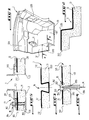
- Figure 1 is a half perspective view of an acoustic insulation device for a motor vehicle.
- Figure 2 is a partial section along line II-II of Figure 1.
- Figure 3 is a view similar to Figure 2, which shows an embodiment of means for securing the foam covering and the heavy mass of the device.
- Figure 4 is a view similar to Figure 3, which shows another embodiment of securing means.
- Figure 5 is a view similar to Figure 4, which shows yet another embodiment of securing means.
- the reference numeral 1 designates an acoustic insulation device.
- the device 1 is provided for any motor vehicle.
- FIG. 5 only a sheet of a front apron 2 of this vehicle is seen, that is to say the partition or structure which separates the engine compartment and the passenger compartment.
- the device 1 comprises in particular a piece of inert material 12, commonly called “heavy mass”, as well as a layer or foam coating 13, interposed between the heavy mass 12 and the structure to be insulated, namely the passenger compartment of the vehicle.
- the foam covering 13 is in simple contact with the heavy mass 12.
- the covering 13 is here constituted by at least one insert, which is fixed to the heavy mass 12 using removable means of attachment, including several embodiments will be described later.
- the heavy mass 12 is a thermoformed shell of PVC, rubber or the like, the shape of which corresponds, as can be seen in FIG. 1, substantially inside the passenger compartment of the vehicle equipped with the device. 1, near its front apron 2.
- the shell 12 comprises a front part 12A corresponding to the apron 2, as well as two side parts 12B, approximately vertical and only one of which is illustrated.
- a part 12C of the shell 12 extends substantially horizontally so as to cover the floor of the vehicle, and comprises a central boss 12D which covers a transmission tunnel of this vehicle.
- the covering 13 is constituted by a layer or by a plurality of approximately adjoining plates, produced in a foaming material such as polyurethane.
- the covering 13, the shape of which corresponds substantially to the external face 122 of the shell 12, that is to say its face facing the structure to be insulated, will be manufactured separately from the shell 12, using with appropriate tools, such as for example a mold.
- the securing means positively connect certain predetermined areas only of the heavy mass 12 and the coating 13, so that their separation for recycling is here quick and easy.
- the device 1 comprises securing means 15. These means 15 allow to fix the coating 13 on the shell 12 by direct or elastic stapling, commonly called “clipping".
- the means 15 include in particular an element 153, integral with the covering 13 and projecting from a face 132 of the latter.
- the face 132 is arranged opposite the shell 12, and more precisely opposite a through opening 152 which crosses the heavy mass.
- the element 153 came integrally with the coating 13.
- the latter may be constituted by an insert such as a clip.
- the element 153 comprises a body 151 of roughly cylindrical shape, the cross section of which has an area substantially equal to that of the opening 152, and comprises at its free end a locking head 154.
- the locking head 154 whose cross-sectional area is greater than that of the opening 152, is pressed elastically against a face 125 of the heavy mass.
- the face 125 is opposite to the face 122, and therefore to the coating 13.
- the means 15 are put in place by placing the head 154 opposite the opening 152, then by introducing into the covering 13, a tool 156 in the form of a conical finger. Then, the finger 156 is moved in the direction of the arrow M (FIG. 4), until the head 154 is elastically deformed to pass through the opening 152 and comes to rest against the face 125, in the fixing position.
- the disassembly of the connection thus obtained is carried out by applying to the head 154, in a direction opposite to M, a tool of section smaller than that of the opening 152, until the element 153 escapes from this one, or even by pulling from the other face.
- removable means of attachment 16 will now be described.
- These means 16 which preferably apply to the case where the covering 13 is constituted by separate foam plates, comprise at least one deformation 162 formed in the heavy mass 12 and projecting from the face 122.
- the height of the deformation 162 is here substantially equal to the thickness of the corresponding plate 13, in order to enclose a rim thereof, and to make the covering 13 integral with the shell 12.
- the deformations 162 can also be reported on the shell 12.
- these could be constituted by angles fixed on the shell 12 so that a shoulder of this angle comes to bear elastically on the face 133 of the covering 13, in order to press it against the face 122 of the hull.
- each deformation 162 (or several deformations jointly) can delimit a cavity which widens towards the bottom and inside which a plate of the covering 13 can be mounted.
- the bottom of such a cavity is the plane of the heavy mass 12 parallel to the face 133, which is surrounded by deformations 162 and against which the face 132 of the corresponding plate 13 comes to bear.
- the area of the bottom of each cavity is equal, if not slightly less, than that of the face 132 of the corresponding plate.
- the walls of each cavity projecting from the bottom are inclined towards the inside of this cavity.
- each cavity is entirely occupied by a covering plate 13.
- the dimensions of the cavities are chosen so that the corresponding plates 13 are housed there with their deformed external edges elastically in compression.
- the sheet 2 has an orifice 22, such as a steering column passage for example.
- a cutout 11 is formed in the covering 13, and another cutout 112, of larger section, is formed in the shell 12.
- the means for securing the heavy mass 12 and the covering 13 are designated at 17, and include a system 18 for biasing the device 1 against the sheet 2.
- the means 17 proper comprise a jacket 172, integrally formed with the covering 13 and extending from the face 132, inside the cutout 112.
- the end of the jacket 172 forms a collar 173 which extends towards the outside of the cutout 11, along the face 125 of the shell 12, in the manner of a flap.
- the system 18 comprises a flange 181, which can be pressed against the face 125 of the device 1, as well as at least one clamping member, which makes it possible to urge the flange 181 towards the sheet 2.
- the members tightening devices consist of a plurality of screws 182 distributed around the cutout 11, on each of which a nut 184 can be mounted.
- One end of each screw 182 is made integral with the sheet 2, while its other end projects from a hole formed in the flange 181.
- the screw 182 therefore passes through the flange 181, as well as a hole 183 extending from starting from the device 1, from the face 133 of the layer 13 to the face 125 of the mass 12.
- each device 1 can be equipped with one or more securing means 15, 16 or 17.
Landscapes
- Engineering & Computer Science (AREA)
- Mechanical Engineering (AREA)
- Architecture (AREA)
- Structural Engineering (AREA)
- Chemical & Material Sciences (AREA)
- Combustion & Propulsion (AREA)
- Transportation (AREA)
- Physics & Mathematics (AREA)
- Acoustics & Sound (AREA)
- Vehicle Interior And Exterior Ornaments, Soundproofing, And Insulation (AREA)
- Body Structure For Vehicles (AREA)
Applications Claiming Priority (2)
| Application Number | Priority Date | Filing Date | Title |
|---|---|---|---|
| FR9211780 | 1992-10-05 | ||
| FR9211780A FR2696407B1 (fr) | 1992-10-05 | 1992-10-05 | Dispositif d'isolation acoustique, notamment pour tablier avant de véhicule automobile. |
Publications (2)
| Publication Number | Publication Date |
|---|---|
| EP0592271A1 true EP0592271A1 (de) | 1994-04-13 |
| EP0592271B1 EP0592271B1 (de) | 1998-06-24 |
Family
ID=9434149
Family Applications (1)
| Application Number | Title | Priority Date | Filing Date |
|---|---|---|---|
| EP93402341A Expired - Lifetime EP0592271B1 (de) | 1992-10-05 | 1993-09-24 | Schalldämmungsvorrichtung, insbesondere für Automobil-Vorderschürze |
Country Status (3)
| Country | Link |
|---|---|
| EP (1) | EP0592271B1 (de) |
| DE (1) | DE69319293D1 (de) |
| FR (1) | FR2696407B1 (de) |
Cited By (2)
| Publication number | Priority date | Publication date | Assignee | Title |
|---|---|---|---|---|
| DE19530088A1 (de) * | 1995-08-16 | 1997-02-20 | Abb Patent Gmbh | Wandisolierung für Fahrzeuge |
| CN102317118A (zh) * | 2008-12-23 | 2012-01-11 | 3M创新有限公司 | 交通工具隔音方法和设备 |
Citations (3)
| Publication number | Priority date | Publication date | Assignee | Title |
|---|---|---|---|---|
| DE3809185A1 (de) * | 1987-03-20 | 1988-10-06 | Honda Motor Co Ltd | Bodengruppenkonstruktion eines kraftfahrzeugs |
| DE9107484U1 (de) * | 1991-06-18 | 1991-08-29 | Diedrichs, Helmut W., 6100 Darmstadt | Hitzeschild |
| EP0486427A1 (de) * | 1990-11-12 | 1992-05-20 | Rieter Automotive (International) Ag | Entsorgbarer Hitzeschild |
Family Cites Families (1)
| Publication number | Priority date | Publication date | Assignee | Title |
|---|---|---|---|---|
| US4045076A (en) * | 1976-03-29 | 1977-08-30 | Portland Wire & Iron Works | System for removably securing sound-proofing material to a construction vehicle |
-
1992
- 1992-10-05 FR FR9211780A patent/FR2696407B1/fr not_active Expired - Fee Related
-
1993
- 1993-09-24 EP EP93402341A patent/EP0592271B1/de not_active Expired - Lifetime
- 1993-09-24 DE DE69319293T patent/DE69319293D1/de not_active Expired - Lifetime
Patent Citations (3)
| Publication number | Priority date | Publication date | Assignee | Title |
|---|---|---|---|---|
| DE3809185A1 (de) * | 1987-03-20 | 1988-10-06 | Honda Motor Co Ltd | Bodengruppenkonstruktion eines kraftfahrzeugs |
| EP0486427A1 (de) * | 1990-11-12 | 1992-05-20 | Rieter Automotive (International) Ag | Entsorgbarer Hitzeschild |
| DE9107484U1 (de) * | 1991-06-18 | 1991-08-29 | Diedrichs, Helmut W., 6100 Darmstadt | Hitzeschild |
Cited By (3)
| Publication number | Priority date | Publication date | Assignee | Title |
|---|---|---|---|---|
| DE19530088A1 (de) * | 1995-08-16 | 1997-02-20 | Abb Patent Gmbh | Wandisolierung für Fahrzeuge |
| CN102317118A (zh) * | 2008-12-23 | 2012-01-11 | 3M创新有限公司 | 交通工具隔音方法和设备 |
| CN102317118B (zh) * | 2008-12-23 | 2014-03-12 | 3M创新有限公司 | 交通工具隔音方法和设备 |
Also Published As
| Publication number | Publication date |
|---|---|
| FR2696407B1 (fr) | 1994-12-02 |
| DE69319293D1 (de) | 1998-07-30 |
| FR2696407A1 (fr) | 1994-04-08 |
| EP0592271B1 (de) | 1998-06-24 |
Similar Documents
| Publication | Publication Date | Title |
|---|---|---|
| FR2861353A1 (fr) | Tableau de bord comportant un ensemble de porte de coussin gonflable de securite modulaire | |
| FR2482020A1 (fr) | Structure de glace pour carrosserie de vehicule | |
| FR2896842A1 (fr) | Support antivibratoire hydraulique et son procede de fabrication | |
| EP0970853B1 (de) | Dichte Durchlassvorrichtung eines elektrischen Kabelbaumes durch die Durchführungsöffunug einer Fahrzeugspritzwand und Montageverfahren des elektrischen Kabelbaumes | |
| EP0592271A1 (de) | Schalldämmungsvorrichtung, insbesondere für Automobil-Vorderschürze | |
| FR2729913A1 (fr) | Procede de fabrication d'une piece d'equipement notamment d'un vehicule automobile et planche de bord fabriquee selon ce procede | |
| EP2870056B1 (de) | Unterer querträger zur öffnung einer schalldichten windschutzscheibe | |
| FR2744781A1 (fr) | Dispositif d'obturation d'une ouverture et en particulier d'une ouverture traversant une paroi d'un vehicule automobile | |
| EP0657325B1 (de) | Vorgeformte Abdichtungstrennwand für Kraftfahrzeuge mit einer Aufnahme für Lautsprecher | |
| EP1520772A1 (de) | Unterbauabweiser mit Lärmschutzeigenschaften | |
| EP1095762A1 (de) | Verfahren zur Herstellung einer Verbundplatte, insbesondere ein Fahrzeugdach oder Fussboden eines industriellen Fahrzeugs sowie nach diesem Verfahren hergestellte Platte | |
| WO2022069285A1 (fr) | Véhicule doté d'un élément d'absorption acoustique entre un plancher et une batterie électrique | |
| EP0800132B1 (de) | Bekleidung eines Bedienungshebels in einem Fahrzeug | |
| EP0897508B1 (de) | Luftzufuhrleitung, insbesondere für kraftfahrzeuge, und montageverfahren dafür | |
| FR3014791A1 (fr) | Systeme de securite pour vehicule | |
| WO2000017031A2 (fr) | Structure de support creuse de forme allongee comportant un bouchon anti-effondrement et bouchon anti-effondrement pour une telle structure | |
| FR2868371A1 (fr) | Ensemble de montage d'une barre de toit longitudinale sur un toit d'un vehicule automobile | |
| FR2908365A1 (fr) | Support de haut-parleur pour vehicule | |
| EP4031416B1 (de) | Kraftfahrzeugverkleidungsteil aus expandiertem polymermaterial | |
| FR3128413A1 (fr) | Panneau d'étanchéité pour porte de véhicule automobile | |
| FR2796017A1 (fr) | Appui-tete a entraxe modulable et siege comportant un tel appui-tete | |
| FR2934547A1 (fr) | Dispositif de freinage pour vehicule automobile comportant un moyen de commande traversant un tablier | |
| FR3083168A1 (fr) | Porte laterale de vehicule a caisson integrant une chambre acoustique pour haut-parleur isolee dudit caisson | |
| FR2934548A1 (fr) | Dispositif de freinage pour vehicule automobile comportant un moyen de commande traversant un tablier | |
| FR2851971A1 (fr) | Panneau insonorisant pourvu d'un dispositif de fixation a plusieurs logements |
Legal Events
| Date | Code | Title | Description |
|---|---|---|---|
| PUAI | Public reference made under article 153(3) epc to a published international application that has entered the european phase |
Free format text: ORIGINAL CODE: 0009012 |
|
| AK | Designated contracting states |
Kind code of ref document: A1 Designated state(s): DE GB IT |
|
| 17P | Request for examination filed |
Effective date: 19941012 |
|
| 17Q | First examination report despatched |
Effective date: 19960124 |
|
| GRAG | Despatch of communication of intention to grant |
Free format text: ORIGINAL CODE: EPIDOS AGRA |
|
| GRAG | Despatch of communication of intention to grant |
Free format text: ORIGINAL CODE: EPIDOS AGRA |
|
| GRAG | Despatch of communication of intention to grant |
Free format text: ORIGINAL CODE: EPIDOS AGRA |
|
| GRAH | Despatch of communication of intention to grant a patent |
Free format text: ORIGINAL CODE: EPIDOS IGRA |
|
| GRAH | Despatch of communication of intention to grant a patent |
Free format text: ORIGINAL CODE: EPIDOS IGRA |
|
| GRAA | (expected) grant |
Free format text: ORIGINAL CODE: 0009210 |
|
| AK | Designated contracting states |
Kind code of ref document: B1 Designated state(s): DE GB IT |
|
| PG25 | Lapsed in a contracting state [announced via postgrant information from national office to epo] |
Ref country code: IT Free format text: LAPSE BECAUSE OF FAILURE TO SUBMIT A TRANSLATION OF THE DESCRIPTION OR TO PAY THE FEE WITHIN THE PRE;WARNING: LAPSES OF ITALIAN PATENTS WITH EFFECTIVE DATE BEFORE 2007 MAY HAVE OCCURRED AT ANY TIME BEFORE 2007. THE CORRECT EFFECTIVE DATE MAY BE DIFFERENT FROM THE ONE RECORDED.SCRIBED TIME-LIMIT Effective date: 19980624 Ref country code: GB Free format text: LAPSE BECAUSE OF FAILURE TO SUBMIT A TRANSLATION OF THE DESCRIPTION OR TO PAY THE FEE WITHIN THE PRESCRIBED TIME-LIMIT Effective date: 19980624 |
|
| REF | Corresponds to: |
Ref document number: 69319293 Country of ref document: DE Date of ref document: 19980730 |
|
| PG25 | Lapsed in a contracting state [announced via postgrant information from national office to epo] |
Ref country code: DE Free format text: LAPSE BECAUSE OF FAILURE TO SUBMIT A TRANSLATION OF THE DESCRIPTION OR TO PAY THE FEE WITHIN THE PRESCRIBED TIME-LIMIT Effective date: 19980925 |
|
| GBV | Gb: ep patent (uk) treated as always having been void in accordance with gb section 77(7)/1977 [no translation filed] |
Effective date: 19980624 |
|
| PLBE | No opposition filed within time limit |
Free format text: ORIGINAL CODE: 0009261 |
|
| STAA | Information on the status of an ep patent application or granted ep patent |
Free format text: STATUS: NO OPPOSITION FILED WITHIN TIME LIMIT |
|
| 26N | No opposition filed |