EP0592296A1 - Kernreaktoreinbauten mit Steuerstabführungen - Google Patents
Kernreaktoreinbauten mit Steuerstabführungen Download PDFInfo
- Publication number
- EP0592296A1 EP0592296A1 EP93402431A EP93402431A EP0592296A1 EP 0592296 A1 EP0592296 A1 EP 0592296A1 EP 93402431 A EP93402431 A EP 93402431A EP 93402431 A EP93402431 A EP 93402431A EP 0592296 A1 EP0592296 A1 EP 0592296A1
- Authority
- EP
- European Patent Office
- Prior art keywords
- plate
- lower section
- equipment according
- blades
- section
- Prior art date
- Legal status (The legal status is an assumption and is not a legal conclusion. Google has not performed a legal analysis and makes no representation as to the accuracy of the status listed.)
- Granted
Links
- 239000002826 coolant Substances 0.000 claims abstract description 5
- 125000006850 spacer group Chemical group 0.000 claims description 13
- 230000007704 transition Effects 0.000 claims description 9
- 238000010276 construction Methods 0.000 claims description 2
- 230000000712 assembly Effects 0.000 description 6
- 238000000429 assembly Methods 0.000 description 6
- XLYOFNOQVPJJNP-UHFFFAOYSA-N water Substances O XLYOFNOQVPJJNP-UHFFFAOYSA-N 0.000 description 5
- 230000002745 absorbent Effects 0.000 description 2
- 239000002250 absorbent Substances 0.000 description 2
- 239000000446 fuel Substances 0.000 description 2
- 238000009434 installation Methods 0.000 description 2
- 230000007246 mechanism Effects 0.000 description 2
- 238000006073 displacement reaction Methods 0.000 description 1
- 230000000694 effects Effects 0.000 description 1
- 238000003780 insertion Methods 0.000 description 1
- 230000037431 insertion Effects 0.000 description 1
- 239000003507 refrigerant Substances 0.000 description 1
- 230000035939 shock Effects 0.000 description 1
- 238000001228 spectrum Methods 0.000 description 1
- 238000003466 welding Methods 0.000 description 1
Images


Classifications
-
- G—PHYSICS
- G21—NUCLEAR PHYSICS; NUCLEAR ENGINEERING
- G21C—NUCLEAR REACTORS
- G21C7/00—Control of nuclear reaction
- G21C7/06—Control of nuclear reaction by application of neutron-absorbing material, i.e. material with absorption cross-section very much in excess of reflection cross-section
- G21C7/08—Control of nuclear reaction by application of neutron-absorbing material, i.e. material with absorption cross-section very much in excess of reflection cross-section by displacement of solid control elements, e.g. control rods
- G21C7/10—Construction of control elements
- G21C7/117—Clusters of control rods; Spider construction
-
- G—PHYSICS
- G21—NUCLEAR PHYSICS; NUCLEAR ENGINEERING
- G21C—NUCLEAR REACTORS
- G21C5/00—Moderator or core structure; Selection of materials for use as moderator
- G21C5/02—Details
-
- G—PHYSICS
- G21—NUCLEAR PHYSICS; NUCLEAR ENGINEERING
- G21C—NUCLEAR REACTORS
- G21C7/00—Control of nuclear reaction
- G21C7/06—Control of nuclear reaction by application of neutron-absorbing material, i.e. material with absorption cross-section very much in excess of reflection cross-section
- G21C7/08—Control of nuclear reaction by application of neutron-absorbing material, i.e. material with absorption cross-section very much in excess of reflection cross-section by displacement of solid control elements, e.g. control rods
-
- Y—GENERAL TAGGING OF NEW TECHNOLOGICAL DEVELOPMENTS; GENERAL TAGGING OF CROSS-SECTIONAL TECHNOLOGIES SPANNING OVER SEVERAL SECTIONS OF THE IPC; TECHNICAL SUBJECTS COVERED BY FORMER USPC CROSS-REFERENCE ART COLLECTIONS [XRACs] AND DIGESTS
- Y02—TECHNOLOGIES OR APPLICATIONS FOR MITIGATION OR ADAPTATION AGAINST CLIMATE CHANGE
- Y02E—REDUCTION OF GREENHOUSE GAS [GHG] EMISSIONS, RELATED TO ENERGY GENERATION, TRANSMISSION OR DISTRIBUTION
- Y02E30/00—Energy generation of nuclear origin
- Y02E30/30—Nuclear fission reactors
Definitions
- the present invention relates to upper internal equipment for nuclear reactors and it finds a particularly important application in reactors cooled and moderated by water.
- It relates more particularly to internal equipment surmounting the core of a nuclear reactor, having a bottom plate pierced with coolant outlet openings outside the core, an upper plate, spacer columns connecting the plates, and cluster guides intended for control clusters movable vertically between a position where they are inserted into the core and a position where they are extracted from the latter, at least some of these guides each having an upper section protruding above the upper plate and a section lower extending between the plates and placed in a respective spacer column.
- the cluster guides generally include, at the top, a tube along which are distributed transverse plates individually guiding the rods and, at the bottom, split tubes each assigned to one pencil and sleeves each assigned to two pencils .
- Equipment of this kind is described, for example, in document EP-A-0 456 562 or patent FR 90 05729.
- the present invention aims in particular to provide equipment allowing a simple installation and replacement of the cluster guides placed in columns.
- each of said guides constitutes a cartridge insertable in a column, provided with a flange for fixing to the upper plate provided at its lower part with elastic centering means. in the column.
- the lower section of the guide will include generally several vertical beams connecting the fixing flange to transverse guide plates for the rods, split tubes and rod guide sleeves in the lower part of the lower section.
- the elastic means can then be constituted by longitudinal elastic blades arranged vertically regularly distributed angularly; these blades can for example constitute the terminal part of at least some of the side members, be arranged between them, be arranged in their extension if they end before the bottom. These means can even be elastic blades embedded in a base of the guide and projecting upwards.
- the upper section of the guide has a constitution similar to that of the lower section and the upper equipment comprises, above the columns, covers fixed to the upper plate and each enclosing one of said upper sections.
- the upper section constitutes such a cover.
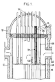
- FIG. 1 a pressurized water reactor of the type shown in FIG. 1, which comprises a tank 10 for resistance to the pressure of the water constituting the coolant and moderator.
- the tank is closed by a cover 12 which carries the mechanisms 14 for moving the control clusters of which only one 16 is shown.
- the tank 10 contains the core 18, formed by juxtaposition of assemblies each having a skeleton and a bundle of fuel rods distributed in a regular, square or triangular network.
- the skeleton of the assemblies includes guide tubes (not shown) in which absorbent rods belonging to the control clusters (or possibly to clusters for varying the energy spectrum of the neutrons) can slide.
- the core is surmounted by an assembly, generally mechanically welded, which is designated by the term of superior internal equipment.
- This set fulfills several functions. It collects the flow of water at high temperature leaving the core upwards and deflects it towards the tubing or tubing 22 leaving the tank 10. It retains the fuel assemblies of the core 18. Finally, it guides the control clusters 16 equipping at least some of the assemblies, during their vertical displacement.
- the upper internal equipment shown in FIG. 1 comprises a lower plate 24, which receives the thrust from the assemblies subjected to the flow of water under pressure, and an upper plate 26 which transfers the result of the forces applied to all of the equipment.
- the plates 24 and 26 are connected by tubular spacer columns 28.
- Cluster guides are provided vertically for each mechanism 14.
- Each cluster guide can be considered to comprise an upper section 30 and a lower section 32.
- the lower sections 32 are contained in corresponding spacer columns 28.
- the upper sections protrude above the upper plate 26, which can be viewed as a support plate for the cluster guides.
- the two low transverse plates 44 and the base 40 are connected by split tubes and sleeves 52 for guiding the rods of the cluster, protecting these rods against the flow of the coolant and replacing the side members between the lowest plate 44c and the base 40.
- These sheaths and split tubes continuously guide the cluster rods over the length 1 (FIG. 2).
- the pencil guide is on the contrary discontinuous in the part of the lower section devoid of sheath and split tube, and in the upper section.
- each of the support columns 28 arranged around a lower section 32 ends in flanges, one of which is fixed to the face facing downward from the upper plate. 26 and the other is fixed to the lower plate 24, for example by screws.
- the reactor is designed so that the refrigerant leaving the assemblies passes through passages 48 drilled in the plate 24, each aligned with an assembly, and the bases 40, openings 54 or openings are formed in the lower part of the columns.
- Each lower section 32 of the cluster guide according to the invention is connected to the respective column by elastic means for centering the lower part of the section (and in certain cases for centering an intermediate part) and by means of orientation. .
- the orientation means form a sliding keying of the base 40 on the column 28 and consist of a pin 34 which engages in a vertical groove of the base 40.
- the elastic centering means can have very diverse constitutions.
- they comprise longitudinal elastic blades arranged vertically and regularly distributed angularly, extending between the lowest transverse plate 44c and the base 40.
- the blades shown are arranged in the extension of the side members 38 and are radially in alignment with the sleeves intended to guide two rods at the same time. But this provision is not the only possible one.
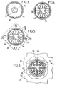
- the means illustrated in FIGS. 2, 7, 8 and 9 comprise four elastic blades 56 fixed to the lower section and respective support pads 58 mounted on the spacer column 28.
- the ends of each blade 56 have a mounting connection l one with the lowest transverse plate 44c, the other with the base 40.
- these blades can be welded at their ends in notches.
- FIG. 7 it can be seen in FIG. 7 that the blade 56, under the effect of a horizontal force, can deform, until it comes into contact and bears in its central part with the sheath 52, which constitutes a stop and limit lateral movement of the cartridge.
- each blade 56 In its deformable part, each blade 56 has two bosses 60 for bearing on a respective pad 58.
- the pads can be mounted in slots or grooves in the spacer column 28 and have a rear edge 62 for welding against the external wall of the spacer column 28.
- the flexible blade 56a is still embedded at its two ends in the lower plate 44c and in the base 40 but its section is different, in the form of a very flat triangle having a terminal flat 64 bearing on the shoe 58.
- the elastic blades 56b are embedded only in the base 40 and mounted in cantilever.
- the elastic means comprise two sets of blades.
- the blades 56c of one of the sets have a mounting link with the base 40.
- the blades 56d of the other set have an installation link with the lowest transverse guide plate 44c.
- the blades 56c and 56d can be arranged symmetrically and each be provided with a single bearing boss on the pad 58.
- Elastic guide means of the same kind as those shown in FIGS. 7 to 12 can also be placed on other transverse plates 44, so as to have a guide distributed along the lower section.
- FIGS. 4 and 6 can therefore be considered both as sections at levels IV-IV and VI-VI in FIG. 14 as at the corresponding levels in FIG. 2.
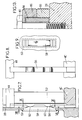
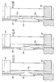
- the upper section is connected to the lower section so as to constitute a monolithic assembly by a transition flange 66 intended to be applied against the upper face of the upper plate 26.
- Longers 68 are arranged in the extension of the side members 38 and also connect plates 44c together and with a high plate 70 provided with a centering device 72.
- This centering device is intended to engage in a housing plate 74 belonging to a cover 76 fixed to the flange of transition 66 and to the top plate 26.
- the means for fixing the cover and the transition flange can have various arrangements.
- the cover is centered on the flange 66 by one or more orientation pins 78 and screws 80 simultaneously fix the transition flange and the cover flange on the plate 26. It may however be more advantageous to secure the flanges before fitting a integrated cluster-hood guide assembly.
- the screws 80 for fixing in the plate 26 then pass through a smooth hole provided in the socket 84.
- the cover 76a is integrated into the cluster guide.
- the side members 38 stop at a transverse plate 44a which replaces the transition flange.
- the transverse guide plates 44b provided in the upper section are directly fixed to the side wall of the cover 76a, for example by screws or fitted pins 88, as shown in FIGS. 14 and 15.
- the assembly of the cluster guide can be fixed using the flange 86a of the cover, using screws 80a which engage directly in the plate 26 ( Figures 14 and 16).
Landscapes
- Physics & Mathematics (AREA)
- Engineering & Computer Science (AREA)
- Plasma & Fusion (AREA)
- General Engineering & Computer Science (AREA)
- High Energy & Nuclear Physics (AREA)
- Chemical & Material Sciences (AREA)
- Chemical Kinetics & Catalysis (AREA)
- Monitoring And Testing Of Nuclear Reactors (AREA)
- Physical Or Chemical Processes And Apparatus (AREA)
- Investigating Or Analyzing Materials By The Use Of Magnetic Means (AREA)
- Organic Low-Molecular-Weight Compounds And Preparation Thereof (AREA)
Applications Claiming Priority (2)
| Application Number | Priority Date | Filing Date | Title |
|---|---|---|---|
| FR9211764A FR2696577B1 (fr) | 1992-10-05 | 1992-10-05 | Equipements internes de réacteur nucléaire à guides de grappe de commande. |
| FR9211764 | 1992-10-05 |
Publications (2)
| Publication Number | Publication Date |
|---|---|
| EP0592296A1 true EP0592296A1 (de) | 1994-04-13 |
| EP0592296B1 EP0592296B1 (de) | 1996-05-15 |
Family
ID=9434137
Family Applications (1)
| Application Number | Title | Priority Date | Filing Date |
|---|---|---|---|
| EP93402431A Expired - Lifetime EP0592296B1 (de) | 1992-10-05 | 1993-10-04 | Kernreaktoreinbauten mit Steuerstabführungen |
Country Status (8)
| Country | Link |
|---|---|
| US (1) | US5416810A (de) |
| EP (1) | EP0592296B1 (de) |
| CN (1) | CN1056703C (de) |
| AT (1) | ATE138219T1 (de) |
| DE (1) | DE69302654T2 (de) |
| ES (1) | ES2086906T3 (de) |
| FR (1) | FR2696577B1 (de) |
| ZA (1) | ZA937373B (de) |
Families Citing this family (3)
| Publication number | Priority date | Publication date | Assignee | Title |
|---|---|---|---|---|
| DE19703226C1 (de) * | 1997-01-29 | 1998-06-18 | Siemens Ag | Halterung für Brennelemente und Verfahren zur Instandsetzung einer solchen Halterung |
| CN102097136B (zh) * | 2010-11-02 | 2012-11-28 | 中国原子能科学研究院 | 核反应堆控制棒导管固定装置 |
| CN103456374B (zh) * | 2013-09-03 | 2015-09-30 | 清华大学 | 球床高温气冷堆反应性控制方法及套叠式控制棒 |
Citations (5)
| Publication number | Priority date | Publication date | Assignee | Title |
|---|---|---|---|---|
| EP0188163A1 (de) * | 1984-12-27 | 1986-07-23 | Framatome | Verstellungs- und Haltevorrichtung für Kontrollstabbündel eines Kernreaktors |
| FR2591018A1 (fr) * | 1985-11-29 | 1987-06-05 | Framatome Sa | Guide de grappe a dispositif de centrage et de positionnement antivibratoire pour reacteur nucleaire |
| EP0266593A2 (de) * | 1986-11-03 | 1988-05-11 | Westinghouse Electric Corporation | Reibungskraftschlüssiges Auflager für das obere Ende eines einseitig eingespannten Regelstabführungsrohres eines Druckwasserreaktors |
| EP0456562A1 (de) * | 1990-05-07 | 1991-11-13 | Framatome | Innere Anlage eines Stabbündelführungskernreaktors |
| EP0467093A1 (de) * | 1990-07-16 | 1992-01-22 | Westinghouse Electric Corporation | Führungsrohreinsatz für Kernreaktor |
Family Cites Families (6)
| Publication number | Priority date | Publication date | Assignee | Title |
|---|---|---|---|---|
| US3977939A (en) * | 1973-10-15 | 1976-08-31 | Westinghouse Electric Corporation | Nuclear reactor internals arrangement |
| US4427621A (en) * | 1981-07-02 | 1984-01-24 | Westinghouse Electric Corp. | Jacking mechanism for upper internals structure of a liquid metal nuclear reactor |
| FR2547100B1 (fr) * | 1983-06-03 | 1985-08-30 | Framatome Sa | Dispositif de guidage des grappes de controle de reacteurs nucleaires |
| FR2576705B1 (fr) * | 1985-01-28 | 1990-06-08 | Framatome Sa | Dispositif d'accouplement de barre de commande et de mecanisme d'entrainement |
| FR2637410B1 (fr) * | 1988-10-04 | 1990-11-02 | Framatome Sa | Dispositif de centrage et de fixation d'une bride de guide de grappe sur une plaque de coeur d'un reacteur nucleaire |
| FR2654545B1 (fr) * | 1989-11-15 | 1993-10-15 | Framatome | Dispositif de calage de la plaque superieure de support des guides de grappes par rapport a la cuve d'un reacteur nucleaire. |
-
1992
- 1992-10-05 FR FR9211764A patent/FR2696577B1/fr not_active Expired - Fee Related
-
1993
- 1993-10-04 DE DE69302654T patent/DE69302654T2/de not_active Expired - Lifetime
- 1993-10-04 CN CN93114157A patent/CN1056703C/zh not_active Expired - Fee Related
- 1993-10-04 EP EP93402431A patent/EP0592296B1/de not_active Expired - Lifetime
- 1993-10-04 ES ES93402431T patent/ES2086906T3/es not_active Expired - Lifetime
- 1993-10-04 AT AT93402431T patent/ATE138219T1/de not_active IP Right Cessation
- 1993-10-05 US US08/131,629 patent/US5416810A/en not_active Expired - Lifetime
- 1993-10-05 ZA ZA937373A patent/ZA937373B/xx unknown
Patent Citations (5)
| Publication number | Priority date | Publication date | Assignee | Title |
|---|---|---|---|---|
| EP0188163A1 (de) * | 1984-12-27 | 1986-07-23 | Framatome | Verstellungs- und Haltevorrichtung für Kontrollstabbündel eines Kernreaktors |
| FR2591018A1 (fr) * | 1985-11-29 | 1987-06-05 | Framatome Sa | Guide de grappe a dispositif de centrage et de positionnement antivibratoire pour reacteur nucleaire |
| EP0266593A2 (de) * | 1986-11-03 | 1988-05-11 | Westinghouse Electric Corporation | Reibungskraftschlüssiges Auflager für das obere Ende eines einseitig eingespannten Regelstabführungsrohres eines Druckwasserreaktors |
| EP0456562A1 (de) * | 1990-05-07 | 1991-11-13 | Framatome | Innere Anlage eines Stabbündelführungskernreaktors |
| EP0467093A1 (de) * | 1990-07-16 | 1992-01-22 | Westinghouse Electric Corporation | Führungsrohreinsatz für Kernreaktor |
Also Published As
| Publication number | Publication date |
|---|---|
| ZA937373B (en) | 1995-04-05 |
| ATE138219T1 (de) | 1996-06-15 |
| ES2086906T3 (es) | 1996-07-01 |
| DE69302654T2 (de) | 1996-10-02 |
| US5416810A (en) | 1995-05-16 |
| DE69302654D1 (de) | 1996-06-20 |
| CN1093195A (zh) | 1994-10-05 |
| CN1056703C (zh) | 2000-09-20 |
| FR2696577B1 (fr) | 1994-12-02 |
| EP0592296B1 (de) | 1996-05-15 |
| FR2696577A1 (fr) | 1994-04-08 |
Similar Documents
| Publication | Publication Date | Title |
|---|---|---|
| CA1171561A (fr) | Assemblage combustible de reacteur nucleaire | |
| EP0456562B1 (de) | Innere Anlage eines Stabbündelführungskernreaktors | |
| FR2574579A1 (fr) | Assemblage de combustible pour reacteur nucleaire | |
| EP0133712A1 (de) | Abstandshalter für Brennstoffbündel eines Kernreaktors | |
| FR2496316A1 (fr) | Assemblage combustible pour reacteurs nucleaires | |
| EP0592296B1 (de) | Kernreaktoreinbauten mit Steuerstabführungen | |
| EP0773554B1 (de) | Einrichtung und Verfahren zum gemeinsamen Lagern von Kernbrennstabbündeln und Steuerstäben | |
| FR2848717A1 (fr) | Procede et dispositif de manutention d'un tube-guide des equipements internes superieurs d'un reacteur nucleaire | |
| EP0025392A1 (de) | Vorrichtung zum Vermeiden des Herausschleuderns einer Kernreaktorbrennstoffanordnung | |
| EP0118355B1 (de) | Brennstoffbündel für einen Kernreaktor | |
| FR2627321A1 (fr) | Equipements internes superieurs de reacteur nucleaire muni d'un dispositif de separation des debits | |
| FR2533350A1 (fr) | Assemblage de combustible nucleaire a crayons remplacables | |
| EP0088675B1 (de) | Brennelementbündel für einen Kernreaktor | |
| EP0329541B1 (de) | Obere Kernreaktoreinbauten mit Bündelführungseinrichtung | |
| EP0229548B1 (de) | Stabbündelführung mit vibrationsarmer Zentrierungs- und Positionierungsvorrichtung für einen Kernreaktor | |
| EP0161170A1 (de) | Kopfstück für Kernbrennstoffbündel | |
| EP0592289B1 (de) | Kernreaktoreinbauten mit Stützsäulen und Steuerstabbündelführungen | |
| EP0021912B1 (de) | Verfahren und Vorrichtung zur Befestigung eines im Kernbrennelementbündel anwesenden Führungsrohres mit den Endplatten dieses Bündels | |
| EP0189718B1 (de) | Aufhängungsanordnung und Verfahren für den Manipulationsstab eines Kontrollbündels im Kernreaktor | |
| EP0262997B1 (de) | Kernbrennstabbündel mit beweglichem End-Abstandshaltergitter | |
| FR2725298A1 (fr) | Coeur d'un reacteur nucleaire a eau sous pression et embout superieur d'un assemblage de combustible du coeur | |
| FR2636766A1 (fr) | Dispositif et procede d'extraction d'un manchon de blocage d'un tube-guide demontable d'un assemblage combustible d'un reacteur nucleaire | |
| FR2915020A1 (fr) | Dispositif et procede de connexion automatique et a distance des conduits de guidage d'un thermocouple des equipements internes superieurs d'un reacteur nucleaire | |
| FR2693825A1 (fr) | Assemblage combustible nucléaire et ensemble grappe-assemblage en comportant application. | |
| EP0493259A1 (de) | Verfahren und Vorrichtung zur Reparatur eines Abstandhalters in einem Kernreaktorbrennstabbündel |
Legal Events
| Date | Code | Title | Description |
|---|---|---|---|
| PUAI | Public reference made under article 153(3) epc to a published international application that has entered the european phase |
Free format text: ORIGINAL CODE: 0009012 |
|
| AK | Designated contracting states |
Kind code of ref document: A1 Designated state(s): AT BE DE ES SE |
|
| 17P | Request for examination filed |
Effective date: 19940616 |
|
| 17Q | First examination report despatched |
Effective date: 19950908 |
|
| GRAH | Despatch of communication of intention to grant a patent |
Free format text: ORIGINAL CODE: EPIDOS IGRA |
|
| GRAA | (expected) grant |
Free format text: ORIGINAL CODE: 0009210 |
|
| AK | Designated contracting states |
Kind code of ref document: B1 Designated state(s): AT BE DE ES SE |
|
| REF | Corresponds to: |
Ref document number: 138219 Country of ref document: AT Date of ref document: 19960615 Kind code of ref document: T |
|
| REF | Corresponds to: |
Ref document number: 69302654 Country of ref document: DE Date of ref document: 19960620 |
|
| REG | Reference to a national code |
Ref country code: ES Ref legal event code: FG2A Ref document number: 2086906 Country of ref document: ES Kind code of ref document: T3 |
|
| PG25 | Lapsed in a contracting state [announced via postgrant information from national office to epo] |
Ref country code: SE Effective date: 19960815 |
|
| PGFP | Annual fee paid to national office [announced via postgrant information from national office to epo] |
Ref country code: AT Payment date: 19961002 Year of fee payment: 4 |
|
| PLBE | No opposition filed within time limit |
Free format text: ORIGINAL CODE: 0009261 |
|
| STAA | Information on the status of an ep patent application or granted ep patent |
Free format text: STATUS: NO OPPOSITION FILED WITHIN TIME LIMIT |
|
| 26N | No opposition filed | ||
| PG25 | Lapsed in a contracting state [announced via postgrant information from national office to epo] |
Ref country code: AT Free format text: LAPSE BECAUSE OF NON-PAYMENT OF DUE FEES Effective date: 19971004 |
|
| BECA | Be: change of holder's address |
Owner name: *AREVA NP1, PLACE DE LA COUPOLE, TOUR AREVA, F-924 Effective date: 20070525 |
|
| BECN | Be: change of holder's name |
Owner name: *AREVA NP Effective date: 20070525 |
|
| PGFP | Annual fee paid to national office [announced via postgrant information from national office to epo] |
Ref country code: DE Payment date: 20101027 Year of fee payment: 18 |
|
| PGFP | Annual fee paid to national office [announced via postgrant information from national office to epo] |
Ref country code: BE Payment date: 20101026 Year of fee payment: 18 |
|
| PGFP | Annual fee paid to national office [announced via postgrant information from national office to epo] |
Ref country code: ES Payment date: 20101026 Year of fee payment: 18 |
|
| BERE | Be: lapsed |
Owner name: *AREVA NP Effective date: 20111031 |
|
| PG25 | Lapsed in a contracting state [announced via postgrant information from national office to epo] |
Ref country code: DE Free format text: LAPSE BECAUSE OF NON-PAYMENT OF DUE FEES Effective date: 20120501 Ref country code: BE Free format text: LAPSE BECAUSE OF NON-PAYMENT OF DUE FEES Effective date: 20111031 |
|
| REG | Reference to a national code |
Ref country code: DE Ref legal event code: R119 Ref document number: 69302654 Country of ref document: DE Effective date: 20120501 |
|
| REG | Reference to a national code |
Ref country code: ES Ref legal event code: FD2A Effective date: 20130417 |
|
| PG25 | Lapsed in a contracting state [announced via postgrant information from national office to epo] |
Ref country code: ES Free format text: LAPSE BECAUSE OF NON-PAYMENT OF DUE FEES Effective date: 20111005 |