EP0592298B1 - Procédé et dispositif de fabrication d'une plaque de gel à membrane microporeuse pour la séparation et le transfert de macromolécules par électrophorèse - Google Patents
Procédé et dispositif de fabrication d'une plaque de gel à membrane microporeuse pour la séparation et le transfert de macromolécules par électrophorèse Download PDFInfo
- Publication number
- EP0592298B1 EP0592298B1 EP93402437A EP93402437A EP0592298B1 EP 0592298 B1 EP0592298 B1 EP 0592298B1 EP 93402437 A EP93402437 A EP 93402437A EP 93402437 A EP93402437 A EP 93402437A EP 0592298 B1 EP0592298 B1 EP 0592298B1
- Authority
- EP
- European Patent Office
- Prior art keywords
- membrane
- gel
- frame
- cassette
- pushers
- Prior art date
- Legal status (The legal status is an assumption and is not a legal conclusion. Google has not performed a legal analysis and makes no representation as to the accuracy of the status listed.)
- Expired - Lifetime
Links
- 239000012982 microporous membrane Substances 0.000 title claims abstract description 22
- 238000000034 method Methods 0.000 title claims abstract description 19
- 229920002521 macromolecule Polymers 0.000 title claims abstract description 12
- 238000004519 manufacturing process Methods 0.000 title claims abstract description 11
- 238000001962 electrophoresis Methods 0.000 title claims abstract description 9
- 230000001131 transforming effect Effects 0.000 title 1
- 239000012528 membrane Substances 0.000 claims abstract description 82
- 239000007788 liquid Substances 0.000 claims abstract description 21
- 238000000926 separation method Methods 0.000 claims abstract description 6
- 238000004891 communication Methods 0.000 claims description 3
- 238000007711 solidification Methods 0.000 claims description 2
- 230000008023 solidification Effects 0.000 claims description 2
- 239000000853 adhesive Substances 0.000 claims 1
- 230000001070 adhesive effect Effects 0.000 claims 1
- 238000005266 casting Methods 0.000 abstract description 12
- 239000000499 gel Substances 0.000 description 70
- 238000004026 adhesive bonding Methods 0.000 description 3
- 238000005470 impregnation Methods 0.000 description 3
- 230000015572 biosynthetic process Effects 0.000 description 2
- 238000000151 deposition Methods 0.000 description 2
- 229920002401 polyacrylamide Polymers 0.000 description 2
- 238000003466 welding Methods 0.000 description 2
- 229920000936 Agarose Polymers 0.000 description 1
- 239000000020 Nitrocellulose Substances 0.000 description 1
- 239000004677 Nylon Substances 0.000 description 1
- 238000009825 accumulation Methods 0.000 description 1
- 230000001464 adherent effect Effects 0.000 description 1
- 239000011543 agarose gel Substances 0.000 description 1
- 230000003749 cleanliness Effects 0.000 description 1
- 238000001816 cooling Methods 0.000 description 1
- 238000007872 degassing Methods 0.000 description 1
- 238000007710 freezing Methods 0.000 description 1
- 230000008014 freezing Effects 0.000 description 1
- 238000009434 installation Methods 0.000 description 1
- 239000000463 material Substances 0.000 description 1
- 229920001220 nitrocellulos Polymers 0.000 description 1
- 229920001778 nylon Polymers 0.000 description 1
- 229920003023 plastic Polymers 0.000 description 1
- 239000004033 plastic Substances 0.000 description 1
- 238000006116 polymerization reaction Methods 0.000 description 1
- 230000001846 repelling effect Effects 0.000 description 1
- 239000010409 thin film Substances 0.000 description 1
Images

Classifications
-
- G—PHYSICS
- G01—MEASURING; TESTING
- G01N—INVESTIGATING OR ANALYSING MATERIALS BY DETERMINING THEIR CHEMICAL OR PHYSICAL PROPERTIES
- G01N27/00—Investigating or analysing materials by the use of electric, electrochemical, or magnetic means
- G01N27/26—Investigating or analysing materials by the use of electric, electrochemical, or magnetic means by investigating electrochemical variables; by using electrolysis or electrophoresis
- G01N27/416—Systems
- G01N27/447—Systems using electrophoresis
- G01N27/44704—Details; Accessories
-
- B—PERFORMING OPERATIONS; TRANSPORTING
- B01—PHYSICAL OR CHEMICAL PROCESSES OR APPARATUS IN GENERAL
- B01D—SEPARATION
- B01D57/00—Separation, other than separation of solids, not fully covered by a single other group or subclass, e.g. B03C
- B01D57/02—Separation, other than separation of solids, not fully covered by a single other group or subclass, e.g. B03C by electrophoresis
Definitions
- the invention relates to a method and a device for manufacturing a place of membrane gel microporous for the separation and transfer of macromolecules by electrophoresis, the process and the device using a cassette comprising a frame rectangular and a removable bottom plate, in which the gel is poured in liquid form.
- This process and this device make it possible to manufacture gel sheets with one side covered an adherent microporous membrane, generally nitrocellulose or "nylon", and which meet a certain number of criteria such as gel homogeneity, consistency of its thickness, the absence of air bubbles between the gel and the membrane, the flatness of the membrane and the cleanliness of the free face thereof.
- This method and this device also allow to avoid certain disadvantages of the technique anterior, such as gel overflow on the face free from the membrane, or the formation of folds on the membrane resulting from its elongation during its gel impregnation.
- the subject of the present invention is improvements to the methods and devices described in the aforementioned prior documents, these improvements to simplify and make even easier making a gel plate with microporous membrane.
- the invention therefore provides a manufacturing process a microporous membrane gel plate for separation and transfer of macromolecules by electrophoresis, the gel being poured in liquid form in a cassette comprising a rectangular frame and a removable bottom plate to fill the space delimited in the frame between the bottom plate and a microporous membrane previously fixed on the frame, characterized in that it consists in putting the membrane in substantially uniform tension by exerting tensile forces on its edges before the gel is poured and keep the membrane under tension during the solidification of the gel, the tensile forces being permanently exercised on two opposite edges of the membrane, in radiating directions from a fixed point located on a median axis of the membrane, by example in the vicinity of a transverse edge thereof.
- the method according to the invention presents the advantage that the microporous membrane is laid on the rectangular frame and energized before casting liquid gel, which is much simpler and easier to realize that gradually depositing a membrane microporous on a layer of liquid gel
- the method also consists in casting the gel in the cassette by one end of it, this end being opposite to that comprising a comb carried by the bottom plate to form in the plate freezing of the wells for receiving macromolecule samples.
- the end of the cassette used for pouring the gel is slightly raised, which gradually expels the air between the bottom plate and the membrane as you go pouring the gel, to guarantee the absence of bubbles air between the gel and the membrane.
- the method according to the invention consists beforehand to fix, for example by gluing, two bars longitudinally extendable on the two aforementioned edges of the membrane, and to exert the aforementioned tensile forces on the membrane by means of pushers which are engaged in orifices of said bars and elastically stressed outwards by springs, the pushers and the springs being housed in guide grooves formed in the sides framework correspondents.
- the traction permanently exerted on the edges of the membrane allows in particular to absorb elongation of the membrane resulting from its impregnation by the liquid gel when it is poured, and guarantees the flatness of the membrane.
- the invention also provides a device for manufacturing a microporous membrane gel plate for separation and transfer of macromolecules by electrophoresis, comprising a cassette formed by a frame rectangular and a bottom plate, means of fixation of a microporous membrane on the frame and means for pouring liquid gel inside the frame on the bottom plate, the casting means being mounted at one end of the cassette and comprising a channel passage of gel opening into the cassette between the bottom plate and no membrane attached to the frame, characterized in that two opposite longitudinal uprights of the frame include cooperating traction means with two opposite longitudinal edges of the membrane for tension it in a substantially uniform fashion before pouring the gel and in that the pouring means gel include a reservoir carried by a plate support intended to be introduced as a seal in a open end of the frame, the tank having a cylindrical base rotatably mounted in a housing cylindrical of the support plate and formed with a channel gel outlet intended to be brought, by rotation, in communication with a conduit of the support plate whose the ends open respectively into the housing cylindrical and inside the frame between the
- This tank makes it possible to dose the amount of gel needed to make a plate of gel then, by rotation on the support plate, allow this quantity to flow into the cassette dosed with gel.
- the structure of these casting means makes it possible to more than automatically degassing the gel and an evacuation of the air contained in the outlet channel of the tank, before pouring the gel.
- the aforementioned traction means include pushers guided in grooves on the aforementioned sides of the frame and stressed outwards by springs, these pushers comprising means for hooking the edges of the membrane.
- the device comprises also means acting on the pushers for the move inward of the frame in the opposite direction to the action of the springs, in a position allowing the laying an untensioned membrane on the cassette and the attachment of this membrane on the pushers.
- the device includes a support shelf and cassette positioning, and two movable arms mounted on the shelf on either side of the cassette and wearing fingers intended to be engaged in guide grooves for the pushers, these arms being movable between an active position where the fingers are engaged in the guide grooves of the pushers and push these towards the inside of the frame, and a inactive position where the fingers are separated from the grooves for guiding the pushers.
- the method and the device according to the invention greatly facilitate the manufacture a plate of microporous membrane gel, so that this production can be carried out at a high rate by non-specialized personnel, the gel plates as well manufactured with homogeneous and reproducible qualities.
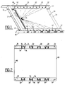
- Figures 1 and 2 respectively represent a manufactured gel plate in a cassette according to the invention, and the microporous membrane associated with this gel plate.
- the cassette of Figure 1 includes, like the cassette of the above-mentioned International Application WO93 / 01491 the content of which is incorporated here by reference, a framework rectangular 10 formed by two longitudinal uprights 12 interconnected at their ends by crossbars 14, and a removable bottom plate 16 (shown schematically in Figure 6) which is guided in grooves 18 of the internal faces of the longitudinal uprights 12 and which is provided at one of its ends a comb 20 carrying a row of teeth 22 intended for form wells 24 in the gel plate 26 produced at by means of the cassette, the bottom plate 16 being removed of the cassette when using the gel plate 26 for separation and transfer of macromolecules by electrophoresis.
- the microporous membrane 28 associated with the gel plate 26 is shown in Figure 2 and is formed a very thin film having for example a thickness of the order of 0.15 mm, a width of 170 mm and a length 225 mm in a particular embodiment, on the two longitudinal sides of which are fixed, by example by gluing or by welding, two bars 30 of plastic material having for example a thickness of in the order of a millimeter and a width of about 15 mm in a particular embodiment, and which include on the one hand, elongated orifices 32 for hooking on means of tensioning the membrane and on the other hand transverse slots 34 opening alternately on a edge and on the other of the bar 30 to allow a longitudinal extension thereof.
- the tensioning means of the membrane 28 are provided in the longitudinal uprights 12 of the frame 10 and understand, as best seen in the enlarged view in section of FIG. 3, pushers 36 guided in grooves 38 of the uprights 12 and the springs 40 housed in the grooves between the bottom of these and the pushers 36 to elastically urge the latter towards outside the frame 10.
- the pushers 36 include each, on their upper face, a pin 42 passing to through an elongated lumen 44 of the upper face of the amount 12 corresponding and intended to be engaged in a orifice 32 of a strip 30 of the membrane, for the attachment of the membrane to the tensioning means.
- the grooves 38 and the elongated lights 44 uprights 12 are radially oriented by relative to a fixed point 46 which is located on the longitudinal axis median of gel plate 26 and membrane 28, in the immediate vicinity of the edge of the gel plate with sinks 24.
- the grooves 38 for guiding the pushers 36 open to the outside of the uprights 12 in holes formed in two side bars 48 which are fixed on the outside faces of the uprights 12.
- the upper faces of the uprights 12 are inclined transversely outwards and downwards, as well as the grooves 38 for guiding the pushers 36, so that the membrane 28 can be properly applied on the edges formed by the internal longitudinal edges 50 of the amounts 12.
- the membrane thus prepared is then laid on the upper face of the frame 10 provided with the plate bottom 16.
- the pins 42 of the pushers 36 are engaged in the orifices 32 of the strips 30 of the membrane, which is then substantially uniform tensioning by the springs 40 elastically pushing the pushers 36 towards outside.
- the elongation of the membrane is around percent.
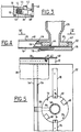
- the membrane delimits with the frame 10 and the bottom plate 16 a corresponding space exactly to the gel plate 26 to be manufactured and which is open only at the end of the frame 10 opposite to that closed by the comb 20 carried by the plate bottom 16. It is through this open end that the gel goes be poured in liquid form in this space, until the completely fill, using the device shown in Figures 4 and 5.
- This pouring device essentially comprises a support plate 52 intended to come to engage substantially sealed in the open end of the frame 10 between the bottom plate 16 and the membrane 28, the transverse front edge 54 of this support plate comprising an upper rib 56 forming an edge on which the membrane 28 applies.
- the casting device further comprises a vertical reservoir 58 substantially funnel-shaped, having a cylindrical base 60 engaged with very little play in a cylindrical housing 62 with the closed bottom of the support plate, such so that the base 60 of the tank can rotate in this housing around a vertical axis.
- a radial groove 64 is formed in the underside of the cylindrical base 60 of the tank, to communicate the interior of this tank with the cylindrical housing 62 formed in the support plate 52.
- a longitudinal duct 66 is formed in the support plate 52 to establish a communication between the cylindrical housing 62 and the front transverse edge 54 of the support plate.
- the base 60 of the reservoir 58 is held in the cylindrical housing 62 of the support plate by a bayonet mounting, by means of two diametrically 68 notches opposites formed in the periphery of the base 60 of the reservoir, and of two fingers 70 fixed in alignment on the upper face of the support plate 52, on the and on the other side of the axis of the cylindrical housing 62, the ends opposite the fingers 70 extending above and inward of cylindrical housing 62 over distances smaller than the dimensions of the notches 68 of the tank base.
- This pouring device is used in the way next :
- the reservoir 58 is first mounted on the support plate 52, its cylindrical base 60 being brought in the cylindrical housing 62 with the notches 68 aligned on the ends of fingers 70, then we do turn the base 60 of the tank in the cylindrical housing 62 so that the ends of the fingers 70 apply elastically to the upper face of the base 60 of the tank and keep it firmly in the cylindrical housing 62.
- Notches 72, 74 are advantageously formed on the upper face of the base 60, to receive a projection of corresponding shape provided at the end of the fingers 70 and determine precisely two angular positions of the reservoir 58 around its axis, the first angular position defined by the notches 72 being such that the groove 64 is not aligned with conduit 66 and is closed by the wall of the housing cylindrical 62, the second defined angular position by the notches 74 being such that the groove 64 is aligned with conduit 66 to allow liquid gel contained in the tank 58 to flow to inside the cassette.
- the support plate 52 is mounted in the end open the cassette as shown in the figures 4 and 5.
- a plate 76 comprising elastically deformable longitudinal fingers 78, can be fixed under the support plate 52 so that fingers 78 rest elastically on the underside of the bottom plate 16 to hold the device casting in place on the cassette.
- the membrane 28 can be mounted on the frame 10 before or after mounting the casting device on the frame.
- the end of the cassette containing the casting is slightly higher than its opposite end comprising the comb 20, due to the presence of the fixing plate 76, which creates a slight slope descending towards the comb 20.
- a dosed amount of liquid gel (for example agarose or polyacrylamide) is poured into the tank 58 and comes to fill the groove 64, expelling the air contained in this groove by the slight clearance between the periphery of base 60 and the cylindrical wall of the housing 62, this game having for example a value of the order 0.01 mm allowing air to escape while prohibiting the passage of liquid gel.
- liquid gel for example agarose or polyacrylamide
- the liquid gel thus gradually fills the space defined in box 10 between the plate bottom 16 and the tensioned membrane 28.
- the air contained in this space is gradually evacuated between the membrane 28 and the rib 56 of the support plate 52.
- the membrane 28 has tends to elongate, and this elongation is automatically gradually taken up by the tensioning means constituted by pushers 36 and associated springs 40.
- the pouring device When the gel is solidified, the pouring device from the end of the cassette into which he was engaged.
- This tool includes a support shelf 76 comprising positioning means (not shown) of the frame 10 provided with the bottom plate 16.
- This shelf 76 is equipped with means for repelling towards the inside of the frame the means of tensioning the membrane, so that it is sufficient to lay the membrane 28 provided with its two bars 30 on the top of the frame, so that the pins 42 of the tensioning means engage in the holes 32 of the bars.
- the means shown on the right side of Figure 6 which include movable fingers 86 guided in translation in the extension of the grooves 38 receiving the pushers 36, these fingers 86 comprising at their outer end a stud 88 engaged in a guide groove 90 of a zipper 92 extending along an upright 12 of the frame 8.
- the orientations of the grooves 90 of the pull tab 92 are such that when the zipper is moved in one direction the along the upright 12 of the frame, the fingers 86 are introduced in the guide grooves 38 of the pushers 36 and move these to the inside of the frame and, when the pull tab 92 is moved in the other direction, the fingers 86 have come out of the grooves 38 for guiding the pushers 36.
Landscapes
- Health & Medical Sciences (AREA)
- Life Sciences & Earth Sciences (AREA)
- Chemical & Material Sciences (AREA)
- Molecular Biology (AREA)
- Chemical Kinetics & Catalysis (AREA)
- Electrochemistry (AREA)
- Biochemistry (AREA)
- Analytical Chemistry (AREA)
- Physics & Mathematics (AREA)
- General Health & Medical Sciences (AREA)
- General Physics & Mathematics (AREA)
- Immunology (AREA)
- Pathology (AREA)
- Engineering & Computer Science (AREA)
- Environmental & Geological Engineering (AREA)
- Separation Using Semi-Permeable Membranes (AREA)
Description
- la figure 1 est une vue schématique en perspective d'une plaque de gel fabriquée dans une cassette selon l'invention, la membrane microporeuse étant retirée pour plus de clarté ;
- la figure 2 est une vue schématique en plan de la membrane microporeuse ;
- la figure 3 est une vue partielle en coupe, à plus grande échelle, d'un moyen de traction d'une membrane microporeuse ;
- la figure 4 est une vue partielle en coupe longitudinale des moyens de coulée de gel ;
- la figure 5 est une vue schématique partielle en coupe selon la ligne V-V de la figure 4 ;
- la figure 6 représente schématiquement deux formes de réalisation des moyens utilisés pour la pose d'une membrane sur une cassette.
Claims (9)
- Procédé de fabrication d'une plaque de gel à membrane microporeuse pour la séparation et le transfert de macromolécules par électrophorèse, le gel étant coulé sous forme liquide dans une cassette comprenant un cadre rectangulaire (10) et une plaque de fond (16) amovible et venant remplir l'espace délimité dans le cadre (10) entre la plaque de fond et une membrane microporeuse (28) préalablement fixée sur le cadre (10), caractérisé en ce qu'il consiste à mettre la membrane (28) en tension de façon sensiblement uniforme en exerçant des forces de traction sur ses bords avant la coulée du gel et à maintenir la membrane (28) sous tension pendant la solidification du gel, les forces de traction étant exercées en permanence sur deux bords opposés de la membrane (28), dans des directions rayonnantes à partir d'un point fixe (46) situé sur un axe médian de la membrane, par exemple au voisinage d'un bord transversal de celle-ci.
- Procédé selon la revendication 1, caractérisé en ce qu'il consiste à couler le gel dans la cassette par une extrémité de celle-ci, cette extrémité étant opposée à celle comprenant un peigne (20) porté par la plaque de fond (16) pour former dans la plaque de gel des puits (24) de réception d'échantillons de macromolécules.
- Procédé selon la revendication 1 ou 2, caractérisé en ce qu'il consiste préalablement à fixer, par exemple par collage, deux barrettes (30) longitudinalement extensibles sur les deux bords précités de la membrane (28), et à exercer les forces de traction sur la membrane au moyen de poussoirs (36, 42) engagés dans des orifices (32) desdites barrettes et sollicités élastiquement vers l'extérieur par des ressorts (40), les poussoirs et les ressorts étant logés dans des rainures de guidage (38) formées dans les montants correspondants (12) du cadre.
- Dispositif de fabrication d'une plaque de gel à membrane microporeuse pour la séparation et le transfert de macromolécules par électrophorèse, comprenant une cassette formée d'un cadre rectangulaire (10) et d'une plaque de fond (16), des moyens de fixation d'une membrane microporeuse (28) sur le cadre (10) et des moyens de coulée de gel liquide à l'intérieur du cadre sur la plaque de fond, les moyens de coulée (52, 58) étant montés à une extrémité de la cassette et comprenant un canal (64, 66) de passage de gel débouchant dans la cassette entre la plaque de fond (16) et une membrane (28) fixée sur le cadre, caractérisé en ce que deux montants longitudinaux opposés (12) du cadre comprennent des moyens de traction (36, 40, 42) coopérant avec deux bords longitudinaux opposés de la membrane (28) pour mettre celle-ci en tension de façon sensiblement uniforme avant la coulée du gel et en ce que les moyens de coulée du gel comprennent un réservoir (58) porté par une plaque support (52) destinée à être introduite à étanchéité dans une extrémité ouverte du cadre (10), le réservoir comportant une base cylindrique (60) montée à rotation dans un logement cylindrique (62) de la plaque support et formée avec un canal (64) de sortie de gel destiné à être amené, par rotation, en communication avec un conduit (66) de la plaque support dont les extrémités débouchent respectivement dans le logement cylindrique (62) et à l'intérieur du cadre entre la plaque de fond (16) et la membrane (28) tendue.
- Dispositif selon la revendication 4, caractérisé en ce que les moyens de traction comprennent des poussoirs (36) guidés dans des rainures (38) des montants précités du cadre et sollicités vers l'extérieur par des ressorts (40), les poussoirs comportant des moyens (42) d'accrochage des bords de la membrane (28).
- Dispositif selon la revendication 5, caractérisé en ce que les poussoirs (36) comportent des pions (42) destinés à être introduits dans des orifices (32) formés dans des barrettes (30) longitudinalement extensibles, qui sont fixées sur les bords précités de la membrane (28).
- Dispositif selon la revendication 5 ou 6, caractérisé en ce qu'il comprend des moyens (78, 82 ; 84, 86-92) agissant sur les poussoirs (36) pour les déplacer vers l'intérieur du cadre, dans le sens opposé à l'action des ressorts (40), dans une position permettant la pose sur la cassette d'une membrane (28) non tendue, et l'accrochage de cette membrane sur les poussoirs.
- Dispositif selon la revendication 7, caractérisé en ce qu'il comprend une tablette (76) de support et de positionnement de la cassette, et deux bras (78, 92) mobiles montés sur la tablette de part et d'autre de la cassette et portant des doigts (84, 86) destinés à être engagés dans les rainures (38) de guidage des poussoirs, ces bras étant déplaçables entre une position active où les doigts sont engagés dans les rainures de guidage des poussoirs et repoussent ces derniers vers l'intérieur du cadre, et une position inactive où les doigts sont écartés des rainures de guidage des poussoirs.
- Dispositif selon l'une des revendications 4 à 8, caractérisé en ce que la plaque de fond amovible (16) de la cassette comprend, à l'une de ses extrémités, un peigne (20) de formation de puits (24) dans la plaque de gel, ce peigne obturant à étanchéité l'extrémité du cadre (10) opposée à celle recevant les moyens de coulée.
Applications Claiming Priority (2)
| Application Number | Priority Date | Filing Date | Title |
|---|---|---|---|
| FR9212004 | 1992-10-09 | ||
| FR9212004A FR2696657B1 (fr) | 1992-10-09 | 1992-10-09 | Procédé et dispositif de fabrication d'une plaque de gel à membrane microporeuse pour la séparation et le transfert de macromolécules par électrophorèse. |
Publications (2)
| Publication Number | Publication Date |
|---|---|
| EP0592298A1 EP0592298A1 (fr) | 1994-04-13 |
| EP0592298B1 true EP0592298B1 (fr) | 1998-01-21 |
Family
ID=9434319
Family Applications (1)
| Application Number | Title | Priority Date | Filing Date |
|---|---|---|---|
| EP93402437A Expired - Lifetime EP0592298B1 (fr) | 1992-10-09 | 1993-10-05 | Procédé et dispositif de fabrication d'une plaque de gel à membrane microporeuse pour la séparation et le transfert de macromolécules par électrophorèse |
Country Status (9)
| Country | Link |
|---|---|
| US (1) | US5482613A (fr) |
| EP (1) | EP0592298B1 (fr) |
| JP (1) | JPH07502124A (fr) |
| AT (1) | ATE162422T1 (fr) |
| AU (1) | AU5115993A (fr) |
| CA (1) | CA2124959A1 (fr) |
| DE (1) | DE69316506D1 (fr) |
| FR (1) | FR2696657B1 (fr) |
| WO (1) | WO1994008701A1 (fr) |
Families Citing this family (12)
| Publication number | Priority date | Publication date | Assignee | Title |
|---|---|---|---|---|
| EP0783691B1 (fr) * | 1994-09-19 | 2004-12-01 | Invitrogen Corporation | Moule en plastique pour gel d'electrophorese |
| DE19949462A1 (de) * | 1999-10-14 | 2001-04-19 | Universitaetsklinikum Freiburg | Vorrichtung zum Formen von Elektrophorese-Gelen |
| DE10063096C1 (de) * | 2000-12-18 | 2002-09-12 | Gerhard Weber | Elektrophoresevorrichtung, Elektrophoreseverfahren unter Verwendung einer Elektrophoresevorrichtung und Verwendung der Elektrophoresevorrichtung |
| US20040079641A1 (en) * | 2002-10-02 | 2004-04-29 | Qi-Feng Ma | Curved-film mold for preparation of electrophoresis gels |
| US8173002B2 (en) | 2005-02-24 | 2012-05-08 | Life Technologies Corporation | Electro-blotting devices, systems, and kits, and methods for their use |
| US20100044229A1 (en) * | 2008-07-11 | 2010-02-25 | Life Technologies Corporation | Electrophoretically Enhanced Detection of Analytes on a Solid Support |
| US8715476B2 (en) | 2009-12-11 | 2014-05-06 | Bio-Rad Laboratories, Inc. | Instrument for independent electrotransfer in multiple cassettes |
| EP2856132A4 (fr) * | 2012-05-31 | 2016-05-18 | Ge Healthcare Bio Sciences Ab | Cassette de gel d'électrophorèse et procédé de remplissage d'une cassette de gel d'électrophorèse |
| WO2014018721A1 (fr) | 2012-07-25 | 2014-01-30 | Bio-Rad Laboratories, Inc. | Administration ciblée de réactifs par l'intermédiaire de feuilles de transfert à motifs |
| EP2909613B1 (fr) | 2012-10-17 | 2020-09-02 | Bio-rad Laboratories, Inc. | Capture d'image pour grands réseaux d'analytes |
| US9291596B2 (en) | 2013-02-12 | 2016-03-22 | Pierce Biotechnology, Inc. | Electroblot transfer buffer |
| USD738527S1 (en) | 2013-05-28 | 2015-09-08 | Life Technologies Corporation | Electroblotting apparatus |
Family Cites Families (2)
| Publication number | Priority date | Publication date | Assignee | Title |
|---|---|---|---|---|
| FR2670129B1 (fr) * | 1990-12-10 | 1993-04-02 | Bertin & Cie | Procede de preparation d'une membrane garnie d'une couche d'un gel et cadre de support d'une telle membrane concu pour la mise en óoeuvre de ce procede. |
| FR2672822B1 (fr) * | 1991-02-14 | 1993-06-11 | Bertin & Cie | Procede de fabrication d'une plaque de gel pour la separation et le transfert de macromolecules par electrophorese, et les plaques de gel ainsi obtenues. |
-
1992
- 1992-10-09 FR FR9212004A patent/FR2696657B1/fr not_active Expired - Fee Related
-
1993
- 1993-10-05 US US08/244,528 patent/US5482613A/en not_active Expired - Fee Related
- 1993-10-05 DE DE69316506T patent/DE69316506D1/de not_active Expired - Lifetime
- 1993-10-05 JP JP6509692A patent/JPH07502124A/ja active Pending
- 1993-10-05 WO PCT/FR1993/000982 patent/WO1994008701A1/fr not_active Ceased
- 1993-10-05 EP EP93402437A patent/EP0592298B1/fr not_active Expired - Lifetime
- 1993-10-05 CA CA002124959A patent/CA2124959A1/fr not_active Abandoned
- 1993-10-05 AU AU51159/93A patent/AU5115993A/en not_active Abandoned
- 1993-10-05 AT AT93402437T patent/ATE162422T1/de not_active IP Right Cessation
Also Published As
| Publication number | Publication date |
|---|---|
| FR2696657A1 (fr) | 1994-04-15 |
| ATE162422T1 (de) | 1998-02-15 |
| FR2696657B1 (fr) | 1995-01-13 |
| EP0592298A1 (fr) | 1994-04-13 |
| US5482613A (en) | 1996-01-09 |
| CA2124959A1 (fr) | 1994-04-28 |
| JPH07502124A (ja) | 1995-03-02 |
| AU5115993A (en) | 1994-05-09 |
| WO1994008701A1 (fr) | 1994-04-28 |
| DE69316506D1 (de) | 1998-02-26 |
Similar Documents
| Publication | Publication Date | Title |
|---|---|---|
| EP0592298B1 (fr) | Procédé et dispositif de fabrication d'une plaque de gel à membrane microporeuse pour la séparation et le transfert de macromolécules par électrophorèse | |
| CH675404A5 (fr) | ||
| CH635446A5 (fr) | Procede pour introduire automatiquement des films positifs dans les montures a diapositive. | |
| EP1223843B1 (fr) | Appareil distributeur de materiau d'essuyage | |
| FR2600245A1 (fr) | Urinometre et dispositif pour recueillir l'urine | |
| FR2583729A1 (fr) | Appareil simplifie de distribution et de coupe simultanees de bandes de materiaux enroules avec changement automatique du rouleau en service. | |
| BE1028272B1 (fr) | Trancheuse de pain oblique | |
| EP0612476B1 (fr) | Dispositif pour la réalisation de sandwichs | |
| EP0151377A1 (fr) | Dispositif de remplissage de tubes en papier à cigarettes | |
| BE1004855A5 (fr) | Mecanisme d'avancement de feuille en rouleau pour machine a dessiner automatique du type a entrainement de papier. | |
| EP0548335B1 (fr) | Procede et dispositif de fabrication d'une plaque de gel a membrane microporeuse et cassette de gel | |
| EP0343285A1 (fr) | Dispositif de déroulage de corde pour la culture des tomates | |
| CH379380A (fr) | Machine à mouler et emballer en tranches une matière semi-pâteuse, telle par exemple que du fromage fondu | |
| FR2650559A1 (fr) | Dispositif et procede d'ensachage automatique de materiaux | |
| EP1944239A1 (fr) | Procédé pour la préparation d'emballages de compositions florales et/ou végétales | |
| EP0173633B1 (fr) | Machine autorisant le chargement et la coupe d'au moins une extrémité d'un boyau de saucisson et produits similaires | |
| FR2822017A1 (fr) | Dispositif pour la recolte du tabac | |
| BE1000663A5 (fr) | Urinometre et dispositif pour recueillir l'urine. | |
| FR2593995A1 (fr) | Dispositif de manoeuvre d'un film plastique recouvrant les arceaux d'un chassis-tunnel ou d'une serre en vue de leur aeration. | |
| EP0270431A1 (fr) | Procédé de changement d'un produit introduit dans des récipients thermoplastiques et d'au moins un élément décoratif et/ou informatif desdits récipients et mécanisme de raboutage de deux bandes, mécanisme susceptible d'être utilisé pour la mise en oeuvre dudit procédé | |
| FR2874165A1 (fr) | Dispositif de chargement de bobines de materiaux d'essuyage dans un appareil de distribution a coupe automatique de bandes de materiau | |
| EP0526357A1 (fr) | Appareil de distribution et de coupe simultanée de bandes de matériaux enroulés | |
| FR2632609A1 (fr) | Dispositifs de fermeture des emballages en carton ondule ou compact a decoupe en croix et machine pour realiser ces dispositifs | |
| FR2942831A1 (fr) | Appareil pour enduire une bande de papier | |
| FR2577893A1 (fr) | Sachet en matiere synthetique souple comportant sur sa face frontale un moyen de rigidification et de stabilisation |
Legal Events
| Date | Code | Title | Description |
|---|---|---|---|
| PUAI | Public reference made under article 153(3) epc to a published international application that has entered the european phase |
Free format text: ORIGINAL CODE: 0009012 |
|
| AK | Designated contracting states |
Kind code of ref document: A1 Designated state(s): AT BE CH DE DK ES FR GB GR IT LI LU MC NL SE |
|
| 17P | Request for examination filed |
Effective date: 19940920 |
|
| 17Q | First examination report despatched |
Effective date: 19950822 |
|
| GRAG | Despatch of communication of intention to grant |
Free format text: ORIGINAL CODE: EPIDOS AGRA |
|
| GRAH | Despatch of communication of intention to grant a patent |
Free format text: ORIGINAL CODE: EPIDOS IGRA |
|
| GRAH | Despatch of communication of intention to grant a patent |
Free format text: ORIGINAL CODE: EPIDOS IGRA |
|
| GRAA | (expected) grant |
Free format text: ORIGINAL CODE: 0009210 |
|
| AK | Designated contracting states |
Kind code of ref document: B1 Designated state(s): AT BE CH DE DK ES FR GB GR IT LI LU MC NL SE |
|
| PG25 | Lapsed in a contracting state [announced via postgrant information from national office to epo] |
Ref country code: NL Free format text: LAPSE BECAUSE OF FAILURE TO SUBMIT A TRANSLATION OF THE DESCRIPTION OR TO PAY THE FEE WITHIN THE PRESCRIBED TIME-LIMIT Effective date: 19980121 Ref country code: IT Free format text: LAPSE BECAUSE OF FAILURE TO SUBMIT A TRANSLATION OF THE DESCRIPTION OR TO PAY THE FEE WITHIN THE PRESCRIBED TIME-LIMIT;WARNING: LAPSES OF ITALIAN PATENTS WITH EFFECTIVE DATE BEFORE 2007 MAY HAVE OCCURRED AT ANY TIME BEFORE 2007. THE CORRECT EFFECTIVE DATE MAY BE DIFFERENT FROM THE ONE RECORDED. Effective date: 19980121 Ref country code: GR Free format text: LAPSE BECAUSE OF FAILURE TO SUBMIT A TRANSLATION OF THE DESCRIPTION OR TO PAY THE FEE WITHIN THE PRESCRIBED TIME-LIMIT Effective date: 19980121 Ref country code: GB Free format text: LAPSE BECAUSE OF FAILURE TO SUBMIT A TRANSLATION OF THE DESCRIPTION OR TO PAY THE FEE WITHIN THE PRESCRIBED TIME-LIMIT Effective date: 19980121 Ref country code: ES Free format text: THE PATENT HAS BEEN ANNULLED BY A DECISION OF A NATIONAL AUTHORITY Effective date: 19980121 Ref country code: AT Free format text: LAPSE BECAUSE OF FAILURE TO SUBMIT A TRANSLATION OF THE DESCRIPTION OR TO PAY THE FEE WITHIN THE PRESCRIBED TIME-LIMIT Effective date: 19980121 |
|
| REF | Corresponds to: |
Ref document number: 162422 Country of ref document: AT Date of ref document: 19980215 Kind code of ref document: T |
|
| REG | Reference to a national code |
Ref country code: CH Ref legal event code: EP |
|
| REF | Corresponds to: |
Ref document number: 69316506 Country of ref document: DE Date of ref document: 19980226 |
|
| PG25 | Lapsed in a contracting state [announced via postgrant information from national office to epo] |
Ref country code: SE Free format text: LAPSE BECAUSE OF FAILURE TO SUBMIT A TRANSLATION OF THE DESCRIPTION OR TO PAY THE FEE WITHIN THE PRESCRIBED TIME-LIMIT Effective date: 19980421 Ref country code: DK Free format text: LAPSE BECAUSE OF FAILURE TO SUBMIT A TRANSLATION OF THE DESCRIPTION OR TO PAY THE FEE WITHIN THE PRESCRIBED TIME-LIMIT Effective date: 19980421 |
|
| PG25 | Lapsed in a contracting state [announced via postgrant information from national office to epo] |
Ref country code: DE Free format text: LAPSE BECAUSE OF FAILURE TO SUBMIT A TRANSLATION OF THE DESCRIPTION OR TO PAY THE FEE WITHIN THE PRESCRIBED TIME-LIMIT Effective date: 19980422 |
|
| NLV1 | Nl: lapsed or annulled due to failure to fulfill the requirements of art. 29p and 29m of the patents act | ||
| GBV | Gb: ep patent (uk) treated as always having been void in accordance with gb section 77(7)/1977 [no translation filed] |
Effective date: 19980121 |
|
| PG25 | Lapsed in a contracting state [announced via postgrant information from national office to epo] |
Ref country code: LU Free format text: LAPSE BECAUSE OF NON-PAYMENT OF DUE FEES Effective date: 19981005 |
|
| PG25 | Lapsed in a contracting state [announced via postgrant information from national office to epo] |
Ref country code: LI Free format text: LAPSE BECAUSE OF NON-PAYMENT OF DUE FEES Effective date: 19981031 Ref country code: CH Free format text: LAPSE BECAUSE OF NON-PAYMENT OF DUE FEES Effective date: 19981031 Ref country code: BE Free format text: LAPSE BECAUSE OF NON-PAYMENT OF DUE FEES Effective date: 19981031 |
|
| PLBE | No opposition filed within time limit |
Free format text: ORIGINAL CODE: 0009261 |
|
| STAA | Information on the status of an ep patent application or granted ep patent |
Free format text: STATUS: NO OPPOSITION FILED WITHIN TIME LIMIT |
|
| 26N | No opposition filed | ||
| BERE | Be: lapsed |
Owner name: BERTIN & CIE Effective date: 19981031 |
|
| PG25 | Lapsed in a contracting state [announced via postgrant information from national office to epo] |
Ref country code: MC Free format text: LAPSE BECAUSE OF NON-PAYMENT OF DUE FEES Effective date: 19990430 |
|
| REG | Reference to a national code |
Ref country code: CH Ref legal event code: PL |
|
| PG25 | Lapsed in a contracting state [announced via postgrant information from national office to epo] |
Ref country code: FR Free format text: LAPSE BECAUSE OF NON-PAYMENT OF DUE FEES Effective date: 19990630 |
|
| REG | Reference to a national code |
Ref country code: FR Ref legal event code: ST |