EP0592305B1 - Nachverbrenner für Zweistromtriebwerk - Google Patents
Nachverbrenner für Zweistromtriebwerk Download PDFInfo
- Publication number
- EP0592305B1 EP0592305B1 EP93402450A EP93402450A EP0592305B1 EP 0592305 B1 EP0592305 B1 EP 0592305B1 EP 93402450 A EP93402450 A EP 93402450A EP 93402450 A EP93402450 A EP 93402450A EP 0592305 B1 EP0592305 B1 EP 0592305B1
- Authority
- EP
- European Patent Office
- Prior art keywords
- afterburn
- wall
- post
- chamber
- secondary air
- Prior art date
- Legal status (The legal status is an assumption and is not a legal conclusion. Google has not performed a legal analysis and makes no representation as to the accuracy of the status listed.)
- Expired - Lifetime
Links
- 238000011144 upstream manufacturing Methods 0.000 claims description 15
- 238000002347 injection Methods 0.000 claims description 7
- 239000007924 injection Substances 0.000 claims description 7
- 238000001816 cooling Methods 0.000 claims description 6
- 239000003381 stabilizer Substances 0.000 claims 4
- 238000000926 separation method Methods 0.000 claims 1
- 238000002485 combustion reaction Methods 0.000 description 89
- 230000004907 flux Effects 0.000 description 12
- 101100218355 Talaromyces purpureogenus axe-2 gene Proteins 0.000 description 8
- 239000000446 fuel Substances 0.000 description 8
- 244000245420 ail Species 0.000 description 3
- 238000010438 heat treatment Methods 0.000 description 2
- 239000000203 mixture Substances 0.000 description 2
- 230000005855 radiation Effects 0.000 description 2
- 238000005057 refrigeration Methods 0.000 description 2
- 210000003462 vein Anatomy 0.000 description 2
- 238000012550 audit Methods 0.000 description 1
- 239000007800 oxidant agent Substances 0.000 description 1
Images



Classifications
-
- F—MECHANICAL ENGINEERING; LIGHTING; HEATING; WEAPONS; BLASTING
- F01—MACHINES OR ENGINES IN GENERAL; ENGINE PLANTS IN GENERAL; STEAM ENGINES
- F01D—NON-POSITIVE DISPLACEMENT MACHINES OR ENGINES, e.g. STEAM TURBINES
- F01D9/00—Stators
- F01D9/06—Fluid supply conduits to nozzles or the like
- F01D9/065—Fluid supply or removal conduits traversing the working fluid flow, e.g. for lubrication-, cooling-, or sealing fluids
-
- F—MECHANICAL ENGINEERING; LIGHTING; HEATING; WEAPONS; BLASTING
- F23—COMBUSTION APPARATUS; COMBUSTION PROCESSES
- F23R—GENERATING COMBUSTION PRODUCTS OF HIGH PRESSURE OR HIGH VELOCITY, e.g. GAS-TURBINE COMBUSTION CHAMBERS
- F23R3/00—Continuous combustion chambers using liquid or gaseous fuel
- F23R3/02—Continuous combustion chambers using liquid or gaseous fuel characterised by the air-flow or gas-flow configuration
- F23R3/16—Continuous combustion chambers using liquid or gaseous fuel characterised by the air-flow or gas-flow configuration with devices inside the flame tube or the combustion chamber to influence the air or gas flow
- F23R3/18—Flame stabilising means, e.g. flame holders for after-burners of jet-propulsion plants
-
- F—MECHANICAL ENGINEERING; LIGHTING; HEATING; WEAPONS; BLASTING
- F23—COMBUSTION APPARATUS; COMBUSTION PROCESSES
- F23R—GENERATING COMBUSTION PRODUCTS OF HIGH PRESSURE OR HIGH VELOCITY, e.g. GAS-TURBINE COMBUSTION CHAMBERS
- F23R3/00—Continuous combustion chambers using liquid or gaseous fuel
- F23R3/02—Continuous combustion chambers using liquid or gaseous fuel characterised by the air-flow or gas-flow configuration
- F23R3/16—Continuous combustion chambers using liquid or gaseous fuel characterised by the air-flow or gas-flow configuration with devices inside the flame tube or the combustion chamber to influence the air or gas flow
- F23R3/18—Flame stabilising means, e.g. flame holders for after-burners of jet-propulsion plants
- F23R3/20—Flame stabilising means, e.g. flame holders for after-burners of jet-propulsion plants incorporating fuel injection means
Definitions
- a post-combustion device for a double-flow turbo-reactor comprising an external annular casing having a sensitive revolution axis, an exhaust casing contained inside said external casing and comprising an external annular wall and an annular wall. internal, each having the same axis of revolution as the external casing, said external wall being separated from the external casing and delimiting with it a main passage of secondary air, and link arms connecting the internal wall to the external wall, this device post-combustion also comprising a post-combustion wall, annular, having the same axis of revolution as the external casing, arranged inside the external casing by being spaced from it by a determined distance so as to provide a passage for cooling air, and defining a post-combustion chamber.
- US-A-3,118,276 describes a turbofan engine in which the post-combustion device is associated with mixing elements and movable flaps capable of taking secondary air for injecting it into the main vein downstream of the injection ramps.
- Linking arms support the ejection cone by connecting it to the inner wall of the secondary channel and are surrounded by an aerodynamic section envelope through which passes a fuel injector supply line.
- EP-A-0.315.486 also discloses a hollow rectifier placed at the outlet of a turbine, inside which circulates secondary air from the low pressure compressor, for cooling purposes, this air then being injected into the main vein.
- each link arm comprises a box having an upper opening communicating with said main secondary air passage, and comprising a first device for openings, crossing the downstream transverse wall of said link arm and communicating with the post-combustion chamber, and the external radial downstream end of each link arm is adjacent to, and not contiguous with, the post-combustion wall, so that is formed between said link arm and said post-combustion wall, a second secondary air passage communicating the main secondary air passage with the post-combustion chamber.
- the main advantage of a post-combustion device lies in obtaining a homogeneous distribution of the flow gaseous, in particular of the secondary air flow, capable of providing satisfactory operation of the post-combustion.
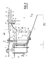
- Each connecting arm 6 of FIGS. 1 and 2 is constituted by two radial walls 22, spaced from one another in order to provide between them a gas conduit 23 which communicates, at the upper part of the connecting arm, by a opening 24, with the passage 25 formed between the external casing 1 and the external wall 3, constituting the main passage for secondary air of the turbomachine.
- the conduit 23 also opens into the post-combustion chamber 9 through openings 26 passing through the downstream transverse wall 27 of the connecting arm 6.
- Each radial wall 22 comprises a radial gutter 28, inside which two conduits are arranged. fuel radials 29, connected to a fuel supply 30 located outside the casing 1.
- Through holes 31, formed in the wall of each fuel conduit 29, extend perpendicular to the wall 22, transversely, and orthogonal to axis 2, constituting as many fuel injection orifices outside the link arm 6, just upstream of the post-combustion chamber 9. Holes 32 crossing the upstream angle of the connection of each gutter 28 with the adjacent wall 22 establish communication between the conduit 23 with the external passages 33 formed between adjacent link arms, communicating the exhaust casing 18 with the post-combustion chamber 9.
- the burner ring 19 is constituted by an annular profile, a section of which by a plane passing through the axis 2, represented in FIG. 4, comprises two wings 20, 35, arranged in a V, the point of the V oriented towards the upstream, in the opposite direction to that of arrow G.
- An O-ring duct 36 is disposed inside the V-section profile, is provided with a multitude of through holes 37 whose axis is oriented parallel and in the direction of arrow G, downstream, and is connected to one or more fuel supply conduits 38.
- the holes 34 of the external wall 3 open into the post-combustion chamber 9 in the vicinity and upstream of the V-shaped section
- Each flame catching arm 17 is constituted by a section having a cross section in V, with two wings 39, with the point of V facing upstream, in the opposite direction to that of arrow G, and, by a conduit oxidizer (air, most often) 40, received between the wings of the profile, being fixed to it by spaced fixing flanges 41.
- This duct 40 has its end 40A, closest to axis 2, blind ; at its other end 40B shaped as an opening for communication with the main secondary air passage 25; and is further provided with several rows, parallel to its axis, through holes 42, the orientations of which all have a component oriented from upstream to downstream.
- the upstream edge 43 of the profile has several series of through holes 44, the axes of which are parallel to the direction of the arrow G and which open directly onto the upstream edge 45 of the conduit 40.
- the conformation and the arrangement of the flame catching arms 17 and of the burner ring 19 make it possible to limit the pressure drops and obtain a low radar equivalent surface.
Landscapes
- Engineering & Computer Science (AREA)
- Chemical & Material Sciences (AREA)
- Combustion & Propulsion (AREA)
- Mechanical Engineering (AREA)
- General Engineering & Computer Science (AREA)
- Physics & Mathematics (AREA)
- Fluid Mechanics (AREA)
- Exhaust Gas After Treatment (AREA)
- Combustion Of Fluid Fuel (AREA)
Claims (10)
- Nachverbrenner für Zweistromtriebwerk, bestehend aus einem ringförmigen Außengehäuse (1) mit einer allgemeinen Drehachse (2), einem Ausstoßgehäuse (18), das in dem genannten Außengehäuse sitzt und aus einer ringförmigen Außenwand (3) und einer ringförmigen Innenwand (4) besteht, die jeweils die gleiche Drehachse haben wie das Außengehäuse, wobei die genannte Außenwand (3) von dem Außengehäuse beabstandet ist und mit diesem einen Sekundärluft-Haupt-durchlaß (25) bildet, und wobei Verbindungsarme (6) die Innenwand (4) und die Außenwand (3) miteinander verbinden, wobei dieser Nachverbrenner ferner eine ringförmige Nachbrennwand (8) mit der gleichen Drehachse wie das Außengehäuse aufweist, die im Inneren des Außengehäuses (1) angeordnet ist und dabei in einem bestimmten Abstand zu diesem angeordnet ist, so daß ein Kühlungsluftdurchgang (12) entsteht, und die eine Nachbrennkammer (9) umgrenzt, wobei jeder Verbindungsarm (6) einen Kasten (23) aufweist, der eine obere Öffnung (24) besitzt, die mit dem genannten Sekundärluft-Hauptdurchlaß (25) in Verbindung steht, sowie eine erste Vorrichtung mit Öffnungen (26) besitzt, die durch die stromabwärts befindliche Querwand (27) des genannten Verbindungsarms verlaufen und mit der Nachbrennkammer (9) in Verbindung stehen, und wobei das äußere radiale stromabwärtige Ende (15) jedes Verbindungsarms sich in der Nähe, aber nicht in Verbindung mit der Nachbrennwand (8) befindet, so daß zwischen dem genannten Verbindungsarm (6) und der genannten Nachbrennwand (8) ein zweiter Sekundärluftdurchlaß (16) entsteht, der den Sekundärluft-Hauptdurchlaß (25) mit der Nachbrennkammer (9) in Verbindung setzt.
- Nachverbrenner nach Anspruch 1,
dadurch gekennzeichnet, daß die genannte Vorrichtung mit Öffnungen mindestens eine Öffnung (26) aufweist, die sich in einer im wesentlichen quer zu der Achse (2) der Nachbrennkammer (9) liegenden Ebene befindet. - Nachverbrenner nach Anspruch 1, dadurch gekennzeichnet, daß die genannte Vorrichtung mit Öffnungen mehrere Löcher (26A) aufweist, die durch zwei Wände (22A) verlaufen, die den Kasten (23A) bilden und einen V-Winkel (22B) miteinander bilden, wobei diese Löcher die Verbindung des Sekundärluft-Hauptdurchlasses (25) mit der Nachbrennkammer (9) herstellen.
- Nachverbrenner nach einem der Ansprüche 1 bis 3, dadurch gekennzeichnet, daß durch die Nachbrennwand (8) mehrere Löcher (46) verlaufen, die die Verbindung des Kühlungsluftdurchgangs (12) mit der Nachbrennkammer (9) herstellen, so daß die genannte Nachbrennwand gekühlt wird.
- Nachverbrenner nach einem der Ansprüche 1 bis 4, dadurch gekennzeichnet, daß er Flammenfangarme (17) aufweist, die sich in radialer Richtung zur Verbindung des Ausstoßgehäuses (18) und der Nachbrennkammer (9) erstrecken, wobei sie mit ihren äußeren Enden an der Außenwand (3) des Ausstoßgehäuses befestigt sind, wobei jede FIammenfangarm-Einheit aus einem länglichen Kasten (40) besteht, der mit einer äußeren axialen Öffnung (40B) zur Verbindung mit dem Sekundärluft-Haupt-durchlaß (25) versehen ist und von einer Wand (40) abgegrenzt wird, durch die mehrere Löcher (42) verlaufen, die die Verbindung zwischen dem Inneren des genannten Kastens und der Nachbrennkammer (9) herstellen.
- Nachverbrenner nach Anspruch 5, dadurch gekennzeichnet, daß jede Flammenfangarm-Einheit (17) ein Außenprofil mit zwei Flügeln (39) aufweist, das einen V-förmigen Querschnitt hat, in dessen Inneren der Kasten (40) angeordnet ist, wobei die Öffnung des V-förmigen Querschnitts zum stromabwärtigen Teil der Nachbrennkammer (9) weist.
- Nachverbrenner nach Anspruch 6, dadurch gekennzeichnet, daß die Kante (43) des Profils, die der Kante des V-förmigen Querschnitts entspricht, mehrere Löcher (44) aufweist, die die Verbindung zwischen dem Ausstoßgehäuse (18) und dem Raum zwischen den beiden Flügeln (39) des Profils herstellen.
- Nachverbrenner nach Anspruch 7, dadurch gekennzeichnet, daß er einen Nachbrennerring (19) aufweist, der koaxial mit der Nachbrennwand (8) in der Nähe des stromabwärtigen Endes (15) der ringförmigen Außenwand (3) des Ausstoßgehäuses und des stromaufwärtigen Endes (14) der Nachbrennwand (8) angeordnet ist undzwischen sich (19), der Nachbrennwand (8) und dem Flammenfangarm (17) mehrere quer verlaufende Durchgänge (21) abgrenzt, die die Verbindung zwischen dem Sekundärluft-Hauptdurchlaß (25) und der Nachbrennkammer (9) herstellen.
- Nachverbrenner nach Anspruch 8, dadurch gekennzeichnet, daß durch die ringförmige Außenwand (3) des Ausstoßgehäuses in der Nähe und stromaufwärts von dem Nachbrennerring (19) mehrere Löcher verlaufen, die die Verbindung zwischen dem Sekundärluft-Hauptdurchlaß (25) und der Nachbrennkammer (9) herstellen.
- Nachverbrenner nach einem der Ansprüche 1 bis 9, dadurch gekennzeichnet, daß der Kasten (23) jedes Verbindungsarms durch Wände (22; 22A) umgrenzt ist, die jeweils mit einem radialen Ablauf (28) versehen sind, in dessen Inneren mindestens eine Leitung (29) zum Einspritzen von Brennstoff durch durchgehende Einspritzöffnungen (31) mit quer verlaufenden Achsen, die senkrecht zu der genannten Drehachse (2) verlaufen, angeordnet ist.
Applications Claiming Priority (2)
| Application Number | Priority Date | Filing Date | Title |
|---|---|---|---|
| FR9211859 | 1982-10-07 | ||
| FR9211859A FR2696502B1 (fr) | 1992-10-07 | 1992-10-07 | Dispositif de post-combustion pour turbo réacteur double flux. |
Publications (2)
| Publication Number | Publication Date |
|---|---|
| EP0592305A1 EP0592305A1 (de) | 1994-04-13 |
| EP0592305B1 true EP0592305B1 (de) | 1996-05-22 |
Family
ID=9434208
Family Applications (1)
| Application Number | Title | Priority Date | Filing Date |
|---|---|---|---|
| EP93402450A Expired - Lifetime EP0592305B1 (de) | 1992-10-07 | 1993-10-06 | Nachverbrenner für Zweistromtriebwerk |
Country Status (5)
| Country | Link |
|---|---|
| US (1) | US5400589A (de) |
| EP (1) | EP0592305B1 (de) |
| JP (1) | JP2968920B2 (de) |
| DE (1) | DE69302788T2 (de) |
| FR (1) | FR2696502B1 (de) |
Families Citing this family (45)
| Publication number | Priority date | Publication date | Assignee | Title |
|---|---|---|---|---|
| US5685140A (en) * | 1995-06-21 | 1997-11-11 | United Technologies Corporation | Method for distributing fuel within an augmentor |
| US5813221A (en) * | 1997-01-14 | 1998-09-29 | General Electric Company | Augmenter with integrated fueling and cooling |
| FR2770284B1 (fr) * | 1997-10-23 | 1999-11-19 | Snecma | Accroche-flamme carbure et a refroidissement optimise |
| US6125627A (en) | 1998-08-11 | 2000-10-03 | Allison Advanced Development Company | Method and apparatus for spraying fuel within a gas turbine engine |
| RU2219440C2 (ru) * | 2001-02-22 | 2003-12-20 | Государственное предприятие Запорожское машиностроительное конструкторское бюро "Прогресс" им. акад. А.Г. Ивченко | Камера сгорания газотурбинного двигателя |
| RU2209992C1 (ru) * | 2002-03-06 | 2003-08-10 | Государственное унитарное предприятие Тушинское машиностроительное конструкторское бюро "Союз" - дочернее предприятие Федерального государственного унитарного предприятия "Российской самолётостроительной корпорации "МиГ" | Форсажная камера двухконтурного турбореактивного двигателя |
| RU2218471C1 (ru) * | 2002-10-02 | 2003-12-10 | Открытое акционерное общество Авиамоторный научно-технический комплекс "Союз" | Форсажная камера газотурбинного двигателя |
| RU2229616C1 (ru) * | 2002-12-15 | 2004-05-27 | Андреев Анатолий Васильевич | Форсажная камера газотурбинного двигателя |
| RU2247852C2 (ru) * | 2002-12-25 | 2005-03-10 | Андреев Анатолий Васильевич | Форсажная камера двухконтурного турбореактивного двигателя |
| US6968694B2 (en) * | 2003-03-13 | 2005-11-29 | United Technologies Corporation | Augmentor |
| FR2856744B1 (fr) * | 2003-06-25 | 2007-05-25 | Snecma Moteurs | Canaux de ventilation sur tole de confluence d'une chambre de post-combustion |
| FR2858661B1 (fr) * | 2003-08-05 | 2005-10-07 | Snecma Moteurs | Dispositif de post-combustion |
| RU2261399C2 (ru) * | 2003-10-27 | 2005-09-27 | Федеральное Государственное Унитарное предприятие "Научно-производственное предприятие "Мотор" (ФГУП "НПП "Мотор") | Кольцевая камера сгорания |
| FR2866675B1 (fr) * | 2004-02-24 | 2008-05-16 | Snecma Moteurs | Procede d'amelioration des performances d'allumage de dispositif de post-combustion pour turboreacteur double flux et dispositif de post-combustion a performance d'allumage amelioree |
| RU2259493C1 (ru) * | 2004-03-11 | 2005-08-27 | Кочетков Борис Федорович | Способ создания реактивной тяги и турбореактивный двигатель для его осуществления |
| FR2869953B1 (fr) * | 2004-05-05 | 2008-07-04 | Snecma Moteurs Sa | Dispositif d'alimentation en air et en carburant d'un anneau-bruleur dans une chambre de postcombustion |
| US6983601B2 (en) * | 2004-05-28 | 2006-01-10 | General Electric Company | Method and apparatus for gas turbine engines |
| FR2873408B1 (fr) * | 2004-07-23 | 2008-10-17 | Snecma Moteurs Sa | Turboreacteur avec un ecran de protection de la rampe de carburant d'un anneau bruleur, l'anneau bruleur et l'ecran de protection |
| US7481059B2 (en) * | 2004-08-12 | 2009-01-27 | Volvo Aero Corporation | Method and apparatus for providing an afterburner fuel-feed arrangement |
| RU2289068C2 (ru) * | 2004-11-30 | 2006-12-10 | Открытое Акционерное Общество "Силовые Машины - Зтл, Лмз, Электросила, Энергомашэкспорт" (Оао "Силовые Машины") | Устройство подачи топлива для малоэмиссионных камер сгорания |
| US7596950B2 (en) * | 2005-09-16 | 2009-10-06 | General Electric Company | Augmentor radial fuel spray bar with counterswirling heat shield |
| RU2300655C1 (ru) * | 2005-12-15 | 2007-06-10 | Открытое акционерное общество Авиамоторный научно-технический комплекс "Союз" | Форсажная камера сгорания турбореактивного двигателя |
| FR2899280B1 (fr) * | 2006-03-30 | 2012-08-31 | Snecma | Dispositif de montage d'une paroi de separation de flux dans une chambre de post-combustion d'un turboreacteur |
| US7552796B2 (en) * | 2006-04-27 | 2009-06-30 | United Technologies Corporation | Turbine engine tailcone resonator |
| RU2335651C1 (ru) * | 2007-02-01 | 2008-10-10 | Федеральное государственное унитарное предприятие "Московское машиностроительное производственное предприятие "Салют" | Форсажная камера газотурбинного двигателя |
| FR2935464B1 (fr) * | 2008-09-01 | 2018-10-26 | Safran Aircraft Engines | Dispositif de fixation d'un bras accroche flammes sur un carter de post-combustion. |
| US9115897B2 (en) | 2008-09-04 | 2015-08-25 | United Technologies Corporation | Gas turbine engine systems and methods involving enhanced fuel dispersion |
| FR2942640B1 (fr) * | 2009-03-02 | 2011-05-06 | Snecma | Chambre de post-combustion pour turbomachine |
| US8713909B2 (en) | 2009-03-04 | 2014-05-06 | United Technologies Corporation | Elimination of unfavorable outflow margin |
| US8763400B2 (en) * | 2009-08-04 | 2014-07-01 | General Electric Company | Aerodynamic pylon fuel injector system for combustors |
| US8726670B2 (en) * | 2010-06-24 | 2014-05-20 | General Electric Company | Ejector purge of cavity adjacent exhaust flowpath |
| US8984859B2 (en) * | 2010-12-28 | 2015-03-24 | Rolls-Royce North American Technologies, Inc. | Gas turbine engine and reheat system |
| US9670844B1 (en) | 2011-11-18 | 2017-06-06 | WRC Jet Innovations, L.P. | Jet engine attachment device |
| JP2013181473A (ja) * | 2012-03-02 | 2013-09-12 | Ihi Corp | アフタバーナ及び航空機エンジン |
| US8534071B1 (en) * | 2012-04-06 | 2013-09-17 | United Technologies Corporation | Engine hot section vane with tapered flame holder surface |
| US10077741B2 (en) | 2012-05-29 | 2018-09-18 | United Technologies Corporation | Spraybar face seal retention arrangement |
| JP6229590B2 (ja) | 2014-04-30 | 2017-11-15 | 株式会社Ihi | アフタバーナ及び航空機エンジン |
| JP6340918B2 (ja) | 2014-05-23 | 2018-06-13 | 株式会社Ihi | 推力増強装置 |
| EP3023696B1 (de) * | 2014-11-20 | 2019-08-28 | Ansaldo Energia Switzerland AG | Nockenlanze für eine Gasturbinenbrennkammer |
| RU2614268C1 (ru) * | 2015-11-11 | 2017-03-24 | Акционерное общество "Научно-производственный центр газотурбостроения "Салют" (АО "НПЦ газотурбостроения "Салют") | Узел подачи топлива в форсажную камеру турбореактивного двухконтурного двигателя |
| RU2621431C1 (ru) * | 2016-02-04 | 2017-06-06 | Акционерное общество "Климов" | Камера смешения форсажной камеры |
| RU205518U1 (ru) * | 2021-03-10 | 2021-07-19 | Акционерное общество "ОДК-Климов" | Форсажная камера двухконтурного турбореактивного двигателя |
| FR3121975B1 (fr) * | 2021-04-19 | 2025-04-04 | Safran Aircraft Engines | Dispositif accroche-flammes pour poscombustion de turboréacteur comprenant des bras de longueurs différentes |
| CN116624898B (zh) * | 2023-04-17 | 2025-06-17 | 中国航发沈阳发动机研究所 | 一种航空发动机加力燃烧室环形火焰稳定器雷达隐身结构 |
| CN118009358A (zh) * | 2024-03-21 | 2024-05-10 | 南京航空航天大学 | 一种气流辅助射流的径向火焰稳定器 |
Family Cites Families (16)
| Publication number | Priority date | Publication date | Assignee | Title |
|---|---|---|---|---|
| US3118276A (en) * | 1964-01-21 | Gas turbine engines | ||
| US2978868A (en) * | 1959-12-21 | 1961-04-11 | Gen Electric | Concentric combustion system with cooled dividing partition |
| US3750402A (en) * | 1963-08-07 | 1973-08-07 | Gen Electric | Mixed flow augmentation system |
| US3315468A (en) * | 1965-10-01 | 1967-04-25 | Gen Electric | Cooled flameholder assembly |
| US3719042A (en) * | 1970-08-04 | 1973-03-06 | United Aircraft Corp | Fuel injection means |
| BE795529A (fr) * | 1972-02-17 | 1973-06-18 | Gen Electric | Allumeur monte sur un dispositif d'augmentation de la poussee de turboreacteurs et refroidi a l'air |
| FR2186608B1 (de) * | 1972-04-17 | 1975-08-29 | Snecma | |
| US3747345A (en) * | 1972-07-24 | 1973-07-24 | United Aircraft Corp | Shortened afterburner construction for turbine engine |
| US5020318A (en) * | 1987-11-05 | 1991-06-04 | General Electric Company | Aircraft engine frame construction |
| US5076062A (en) * | 1987-11-05 | 1991-12-31 | General Electric Company | Gas-cooled flameholder assembly |
| US4901527A (en) * | 1988-02-18 | 1990-02-20 | General Electric Company | Low turbulence flame holder mount |
| US4887425A (en) * | 1988-03-18 | 1989-12-19 | General Electric Company | Fuel spraybar |
| US5203796A (en) * | 1990-08-28 | 1993-04-20 | General Electric Company | Two stage v-gutter fuel injection mixer |
| US5181379A (en) * | 1990-11-15 | 1993-01-26 | General Electric Company | Gas turbine engine multi-hole film cooled combustor liner and method of manufacture |
| FR2672641B1 (fr) * | 1991-02-13 | 1995-01-13 | Snecma | Dispositif de post-combustion a volets pivotants. |
| US5209059A (en) * | 1991-12-27 | 1993-05-11 | The United States Of America As Represented By The Secretary Of The Air Force | Active cooling apparatus for afterburners |
-
1992
- 1992-10-07 FR FR9211859A patent/FR2696502B1/fr not_active Expired - Fee Related
-
1993
- 1993-10-06 US US08/132,245 patent/US5400589A/en not_active Expired - Lifetime
- 1993-10-06 DE DE69302788T patent/DE69302788T2/de not_active Expired - Lifetime
- 1993-10-06 EP EP93402450A patent/EP0592305B1/de not_active Expired - Lifetime
- 1993-10-07 JP JP5276185A patent/JP2968920B2/ja not_active Expired - Fee Related
Also Published As
| Publication number | Publication date |
|---|---|
| EP0592305A1 (de) | 1994-04-13 |
| DE69302788T2 (de) | 1996-11-28 |
| JPH06193509A (ja) | 1994-07-12 |
| JP2968920B2 (ja) | 1999-11-02 |
| FR2696502B1 (fr) | 1994-11-04 |
| FR2696502A1 (fr) | 1994-04-08 |
| US5400589A (en) | 1995-03-28 |
| DE69302788D1 (de) | 1996-06-27 |
Similar Documents
| Publication | Publication Date | Title |
|---|---|---|
| EP0592305B1 (de) | Nachverbrenner für Zweistromtriebwerk | |
| EP0911585B1 (de) | Gekühlter Flammenhalter mit Kraftstoffeinspritzvorrichtung | |
| CA2639980C (fr) | Chambre de combustion d'une turbomachine | |
| EP0326448B1 (de) | Strahl-Mischer mit variablem Durchtrittsquerschnitt für ein Zweistromtriebwerk | |
| FR2743391A1 (fr) | Aube refrigeree de distributeur de turbine | |
| FR2748088A1 (fr) | Optimisation du melange de gaz brules dans une chambre de combustion annulaire | |
| CA2634615C (fr) | Chambre de combustion de turbomachine a circulation helicoidale de l'air | |
| FR2668246A1 (fr) | Chambre de combustion munie d'un dispositif de refroidissement de sa paroi. | |
| FR2481742A1 (fr) | Carter a refroidissement par air et anneau de contrainte, pour rotor de turbine | |
| EP3569929A1 (de) | Einheit für eine brennkammer eines turbotriebwerks | |
| FR2709342A1 (fr) | Dispositif de post combustion d'un turboréacteur. | |
| EP0964206B1 (de) | Brennkammer einer Gasturbine mit verstellbarer Geometrie | |
| FR3122719A1 (fr) | Accroche-flammes pour postcombustion de turboréacteur comprenant des bras à bords de fuite dentelés | |
| EP3638886B1 (de) | Kühlungsanordnung für ein ringformiges aussengehäuse einer turbine | |
| FR2630534A1 (fr) | Echangeur de chaleur pour deux fluides separes dans l'espace et se trouvant a des temperatures differentes | |
| CA2506140A1 (fr) | Dispositif d'alimentation en air et en carburant d'un anneau-bruleur dans une chambre de postcombustion | |
| FR2942640A1 (fr) | Chambre de post-combustion pour turbomachine | |
| EP3504481B1 (de) | Brennkammer mit einem deflektor für verdichtete heissluft, insbesondere für eine turbine zur erzeugung von energie, insbesondere von elektrischer energie | |
| EP0727615A1 (de) | Einspritzdüse für die Brennkammer einer Gasturbine | |
| FR2583109A1 (fr) | Helicoptere a groupe turbomoteur equipe d'un dispositif d'ecran et de dilution du jet de sortie | |
| FR2691235A1 (fr) | Chambre de combustion comprenant un ensemble séparateur des gaz. | |
| EP0235031A1 (de) | Flammenhalter für den Nachtbrenner eines Strahltriebwerks | |
| EP1491752B1 (de) | Belüftungskanäle im Konfluenz-Blech einer Nachverbrennungskammer | |
| EP4327022B1 (de) | Kraftstoffeinspritzvorrichtung für nachbrenner eines turbostrahltriebwerks | |
| FR2673454A1 (fr) | Chambre de combustion comportant une paroi de fond comprenant une pluralite de troncs de cones partiels. |
Legal Events
| Date | Code | Title | Description |
|---|---|---|---|
| PUAI | Public reference made under article 153(3) epc to a published international application that has entered the european phase |
Free format text: ORIGINAL CODE: 0009012 |
|
| 17P | Request for examination filed |
Effective date: 19931020 |
|
| AK | Designated contracting states |
Kind code of ref document: A1 Designated state(s): DE FR GB IT |
|
| 17Q | First examination report despatched |
Effective date: 19950411 |
|
| GRAH | Despatch of communication of intention to grant a patent |
Free format text: ORIGINAL CODE: EPIDOS IGRA |
|
| GRAA | (expected) grant |
Free format text: ORIGINAL CODE: 0009210 |
|
| AK | Designated contracting states |
Kind code of ref document: B1 Designated state(s): DE FR GB IT |
|
| ITF | It: translation for a ep patent filed | ||
| REF | Corresponds to: |
Ref document number: 69302788 Country of ref document: DE Date of ref document: 19960627 |
|
| GBT | Gb: translation of ep patent filed (gb section 77(6)(a)/1977) |
Effective date: 19960619 |
|
| PLBE | No opposition filed within time limit |
Free format text: ORIGINAL CODE: 0009261 |
|
| STAA | Information on the status of an ep patent application or granted ep patent |
Free format text: STATUS: NO OPPOSITION FILED WITHIN TIME LIMIT |
|
| 26N | No opposition filed | ||
| REG | Reference to a national code |
Ref country code: FR Ref legal event code: CL |
|
| REG | Reference to a national code |
Ref country code: GB Ref legal event code: IF02 |
|
| REG | Reference to a national code |
Ref country code: FR Ref legal event code: TP Ref country code: FR Ref legal event code: CD |
|
| REG | Reference to a national code |
Ref country code: FR Ref legal event code: CD |
|
| PGFP | Annual fee paid to national office [announced via postgrant information from national office to epo] |
Ref country code: DE Payment date: 20100930 Year of fee payment: 18 |
|
| PGFP | Annual fee paid to national office [announced via postgrant information from national office to epo] |
Ref country code: GB Payment date: 20110926 Year of fee payment: 19 |
|
| PGFP | Annual fee paid to national office [announced via postgrant information from national office to epo] |
Ref country code: IT Payment date: 20110924 Year of fee payment: 19 |
|
| REG | Reference to a national code |
Ref country code: GB Ref legal event code: 732E Free format text: REGISTERED BETWEEN 20120517 AND 20120523 |
|
| PGFP | Annual fee paid to national office [announced via postgrant information from national office to epo] |
Ref country code: FR Payment date: 20121017 Year of fee payment: 20 |
|
| GBPC | Gb: european patent ceased through non-payment of renewal fee |
Effective date: 20121006 |
|
| PG25 | Lapsed in a contracting state [announced via postgrant information from national office to epo] |
Ref country code: GB Free format text: LAPSE BECAUSE OF NON-PAYMENT OF DUE FEES Effective date: 20121006 Ref country code: DE Free format text: LAPSE BECAUSE OF NON-PAYMENT OF DUE FEES Effective date: 20130501 |
|
| REG | Reference to a national code |
Ref country code: DE Ref legal event code: R119 Ref document number: 69302788 Country of ref document: DE Effective date: 20130501 |
|
| PG25 | Lapsed in a contracting state [announced via postgrant information from national office to epo] |
Ref country code: IT Free format text: LAPSE BECAUSE OF NON-PAYMENT OF DUE FEES Effective date: 20121006 |