EP0592332A1 - Massicot de découpe d'onglets - Google Patents
Massicot de découpe d'onglets Download PDFInfo
- Publication number
- EP0592332A1 EP0592332A1 EP93420372A EP93420372A EP0592332A1 EP 0592332 A1 EP0592332 A1 EP 0592332A1 EP 93420372 A EP93420372 A EP 93420372A EP 93420372 A EP93420372 A EP 93420372A EP 0592332 A1 EP0592332 A1 EP 0592332A1
- Authority
- EP
- European Patent Office
- Prior art keywords
- screw
- nut
- movable part
- rail
- cutter according
- Prior art date
- Legal status (The legal status is an assumption and is not a legal conclusion. Google has not performed a legal analysis and makes no representation as to the accuracy of the status listed.)
- Withdrawn
Links
- 238000004519 manufacturing process Methods 0.000 abstract description 8
- 239000002184 metal Substances 0.000 abstract description 2
- 230000007547 defect Effects 0.000 description 2
- YEXPOXQUZXUXJW-UHFFFAOYSA-N oxolead Chemical compound [Pb]=O YEXPOXQUZXUXJW-UHFFFAOYSA-N 0.000 description 2
- 230000002238 attenuated effect Effects 0.000 description 1
- 238000010276 construction Methods 0.000 description 1
- 230000000694 effects Effects 0.000 description 1
- 238000000034 method Methods 0.000 description 1
Images

Classifications
-
- B—PERFORMING OPERATIONS; TRANSPORTING
- B26—HAND CUTTING TOOLS; CUTTING; SEVERING
- B26D—CUTTING; DETAILS COMMON TO MACHINES FOR PERFORATING, PUNCHING, CUTTING-OUT, STAMPING-OUT OR SEVERING
- B26D1/00—Cutting through work characterised by the nature or movement of the cutting member or particular materials not otherwise provided for; Apparatus or machines therefor; Cutting members therefor
- B26D1/01—Cutting through work characterised by the nature or movement of the cutting member or particular materials not otherwise provided for; Apparatus or machines therefor; Cutting members therefor involving a cutting member which does not travel with the work
- B26D1/12—Cutting through work characterised by the nature or movement of the cutting member or particular materials not otherwise provided for; Apparatus or machines therefor; Cutting members therefor involving a cutting member which does not travel with the work having a cutting member moving about an axis
- B26D1/25—Cutting through work characterised by the nature or movement of the cutting member or particular materials not otherwise provided for; Apparatus or machines therefor; Cutting members therefor involving a cutting member which does not travel with the work having a cutting member moving about an axis with a non-circular cutting member
- B26D1/26—Cutting through work characterised by the nature or movement of the cutting member or particular materials not otherwise provided for; Apparatus or machines therefor; Cutting members therefor involving a cutting member which does not travel with the work having a cutting member moving about an axis with a non-circular cutting member moving about an axis substantially perpendicular to the line of cut
- B26D1/30—Cutting through work characterised by the nature or movement of the cutting member or particular materials not otherwise provided for; Apparatus or machines therefor; Cutting members therefor involving a cutting member which does not travel with the work having a cutting member moving about an axis with a non-circular cutting member moving about an axis substantially perpendicular to the line of cut with limited pivotal movement to effect cut
- B26D1/305—Cutting through work characterised by the nature or movement of the cutting member or particular materials not otherwise provided for; Apparatus or machines therefor; Cutting members therefor involving a cutting member which does not travel with the work having a cutting member moving about an axis with a non-circular cutting member moving about an axis substantially perpendicular to the line of cut with limited pivotal movement to effect cut for thin material, e.g. for sheets, strips or the like
-
- B—PERFORMING OPERATIONS; TRANSPORTING
- B23—MACHINE TOOLS; METAL-WORKING NOT OTHERWISE PROVIDED FOR
- B23Q—DETAILS, COMPONENTS, OR ACCESSORIES FOR MACHINE TOOLS, e.g. ARRANGEMENTS FOR COPYING OR CONTROLLING; MACHINE TOOLS IN GENERAL CHARACTERISED BY THE CONSTRUCTION OF PARTICULAR DETAILS OR COMPONENTS; COMBINATIONS OR ASSOCIATIONS OF METAL-WORKING MACHINES, NOT DIRECTED TO A PARTICULAR RESULT
- B23Q1/00—Members which are comprised in the general build-up of a form of machine, particularly relatively large fixed members
- B23Q1/25—Movable or adjustable work or tool supports
- B23Q1/26—Movable or adjustable work or tool supports characterised by constructional features relating to the co-operation of relatively movable members; Means for preventing relative movement of such members
- B23Q1/262—Movable or adjustable work or tool supports characterised by constructional features relating to the co-operation of relatively movable members; Means for preventing relative movement of such members with means to adjust the distance between the relatively slidable members
-
- B—PERFORMING OPERATIONS; TRANSPORTING
- B23—MACHINE TOOLS; METAL-WORKING NOT OTHERWISE PROVIDED FOR
- B23Q—DETAILS, COMPONENTS, OR ACCESSORIES FOR MACHINE TOOLS, e.g. ARRANGEMENTS FOR COPYING OR CONTROLLING; MACHINE TOOLS IN GENERAL CHARACTERISED BY THE CONSTRUCTION OF PARTICULAR DETAILS OR COMPONENTS; COMBINATIONS OR ASSOCIATIONS OF METAL-WORKING MACHINES, NOT DIRECTED TO A PARTICULAR RESULT
- B23Q5/00—Driving or feeding mechanisms; Control arrangements therefor
- B23Q5/22—Feeding members carrying tools or work
- B23Q5/34—Feeding other members supporting tools or work, e.g. saddles, tool-slides, through mechanical transmission
- B23Q5/38—Feeding other members supporting tools or work, e.g. saddles, tool-slides, through mechanical transmission feeding continuously
- B23Q5/40—Feeding other members supporting tools or work, e.g. saddles, tool-slides, through mechanical transmission feeding continuously by feed shaft, e.g. lead screw
- B23Q5/408—Nut bearings therefor
-
- B—PERFORMING OPERATIONS; TRANSPORTING
- B26—HAND CUTTING TOOLS; CUTTING; SEVERING
- B26D—CUTTING; DETAILS COMMON TO MACHINES FOR PERFORATING, PUNCHING, CUTTING-OUT, STAMPING-OUT OR SEVERING
- B26D1/00—Cutting through work characterised by the nature or movement of the cutting member or particular materials not otherwise provided for; Apparatus or machines therefor; Cutting members therefor
- B26D1/01—Cutting through work characterised by the nature or movement of the cutting member or particular materials not otherwise provided for; Apparatus or machines therefor; Cutting members therefor involving a cutting member which does not travel with the work
- B26D1/12—Cutting through work characterised by the nature or movement of the cutting member or particular materials not otherwise provided for; Apparatus or machines therefor; Cutting members therefor involving a cutting member which does not travel with the work having a cutting member moving about an axis
- B26D1/25—Cutting through work characterised by the nature or movement of the cutting member or particular materials not otherwise provided for; Apparatus or machines therefor; Cutting members therefor involving a cutting member which does not travel with the work having a cutting member moving about an axis with a non-circular cutting member
- B26D1/26—Cutting through work characterised by the nature or movement of the cutting member or particular materials not otherwise provided for; Apparatus or machines therefor; Cutting members therefor involving a cutting member which does not travel with the work having a cutting member moving about an axis with a non-circular cutting member moving about an axis substantially perpendicular to the line of cut
- B26D1/30—Cutting through work characterised by the nature or movement of the cutting member or particular materials not otherwise provided for; Apparatus or machines therefor; Cutting members therefor involving a cutting member which does not travel with the work having a cutting member moving about an axis with a non-circular cutting member moving about an axis substantially perpendicular to the line of cut with limited pivotal movement to effect cut
-
- B—PERFORMING OPERATIONS; TRANSPORTING
- B26—HAND CUTTING TOOLS; CUTTING; SEVERING
- B26D—CUTTING; DETAILS COMMON TO MACHINES FOR PERFORATING, PUNCHING, CUTTING-OUT, STAMPING-OUT OR SEVERING
- B26D3/00—Cutting work characterised by the nature of the cut made; Apparatus therefor
- B26D3/14—Forming notches in marginal portion of work by cutting
-
- B—PERFORMING OPERATIONS; TRANSPORTING
- B26—HAND CUTTING TOOLS; CUTTING; SEVERING
- B26D—CUTTING; DETAILS COMMON TO MACHINES FOR PERFORATING, PUNCHING, CUTTING-OUT, STAMPING-OUT OR SEVERING
- B26D7/00—Details of apparatus for cutting, cutting-out, stamping-out, punching, perforating, or severing by means other than cutting
- B26D7/26—Means for mounting or adjusting the cutting member; Means for adjusting the stroke of the cutting member
- B26D7/2628—Means for adjusting the position of the cutting member
-
- Y—GENERAL TAGGING OF NEW TECHNOLOGICAL DEVELOPMENTS; GENERAL TAGGING OF CROSS-SECTIONAL TECHNOLOGIES SPANNING OVER SEVERAL SECTIONS OF THE IPC; TECHNICAL SUBJECTS COVERED BY FORMER USPC CROSS-REFERENCE ART COLLECTIONS [XRACs] AND DIGESTS
- Y10—TECHNICAL SUBJECTS COVERED BY FORMER USPC
- Y10T—TECHNICAL SUBJECTS COVERED BY FORMER US CLASSIFICATION
- Y10T83/00—Cutting
- Y10T83/869—Means to drive or to guide tool
- Y10T83/8696—Means to change datum plane of tool or tool presser stroke
-
- Y—GENERAL TAGGING OF NEW TECHNOLOGICAL DEVELOPMENTS; GENERAL TAGGING OF CROSS-SECTIONAL TECHNOLOGIES SPANNING OVER SEVERAL SECTIONS OF THE IPC; TECHNICAL SUBJECTS COVERED BY FORMER USPC CROSS-REFERENCE ART COLLECTIONS [XRACs] AND DIGESTS
- Y10—TECHNICAL SUBJECTS COVERED BY FORMER USPC
- Y10T—TECHNICAL SUBJECTS COVERED BY FORMER US CLASSIFICATION
- Y10T83/00—Cutting
- Y10T83/869—Means to drive or to guide tool
- Y10T83/8798—With simple oscillating motion only
- Y10T83/8812—Cutting edge in radial plane
- Y10T83/8814—Adjustable
Definitions
- the invention relates to an office cutter having a chassis which can be placed on a table, said chassis comprising a fixed support plate for one or more sheets to be cut, a movable part mounted in translation relative to said plate, a knife carried by said movable part and capable of struggling in a plane perpendicular to said plate by cooperating with a counter knife to cut the sheet placed on the plate and a translation mechanism with screw and nut to move the mobile part, said knife and counter knife having curved ends for cutting a strip leaving a tab.
- a cutter of the kind mentioned is the subject of European patent application No. 0 491 633, of the applicant, to which the reader requests will advantageously refer for the details of construction and operation of this cutter.
- This cutter is entirely satisfactory, but the screw and nut drive system, essential for the precise positioning of the knife relative to the fixed plate for cutting a miter, requires the use of a perfectly machined long screw, as well than using a relatively powerful drive motor. Likewise, the guide and support slide of the mobile part must be extremely precise and these constraints affect the manufacturing price and therefore the advantage of this device.
- the present invention aims to improve the aforementioned cutter in order to allow its manufacture from standard parts or parts produced by simple methods, while retaining the required precision.
- the cutter according to the invention is characterized in that the connection between said nut and said movable part has a degree of freedom in the direction perpendicular to the axis of the screw to compensate for variations in spacing between the nut and the part mobile when screwing or unscrewing the nut on the screw.
- connection according to the invention between the screw and the movable part.
- This connection of the articulated type is advantageously carried out by a drive finger, carried by the movable part extending perpendicular to the direction of translation and which fits slidingly in a conjugate orifice of the nut.
- the nut of elongated shape, has at each of its ends a section in the form of a cooperating drive and / or guide sleeve. with the screw, said sections being spaced along the screw.
- the two end sections can be threaded or only one of them, the other ensuring only the guide of the sleeve.
- This nut can be produced in different ways, for example by two nuts spaced on the same support or preferably by a tubular sleeve whose central part is enlarged. It is essential to provide a certain clearance between the standard screw and the nut and this clearance causes a noisy operation, which is advantageously mitigated by providing according to the invention an elastic device which biases the nut in support of the screw.
- the guide and support slide of the mobile part consists of a profiled rail and a carriage, one of which is carried by the mobile part and the other of which is integral of the fixed plate.
- the C-shaped section rail is preferably fixed to the fixed plate parallel to the screw and the carriage is then secured to the movable part and is mounted at sliding inside the C-rail to guide the mobile part in translation.
- the rail can be formed by a simple sheet metal whose longitudinal edges are folded and the carriage advantageously comprises two pairs of rollers, spaced along the rail. One of the rollers of each pair cooperates with the lower edge of the rail and the other roller of the pair cooperates with the upper edge of the rail, the two upper rollers being resiliently mounted in support of the rail to compensate for manufacturing defects.
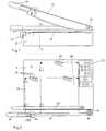
- a chassis 10 of generally parallelepipedal shape has on its upper face a plate 11 for supporting sheets 25, shown in phantom in Figure 2.
- a slide 13 for supporting and guiding a movable part 14.
- a knife 17 is articulated at 16 on the end of the movable part 14 to struggle in a plane perpendicular to the plate 11 under the action of an operating handle 18.
- the movable part 14 carries a counter knife 19 and the frame 10 carries a bar 20 for compressing the sheets 25 to be cut, which are positioned on the plate 11 at predetermined locations 24 by marks or stops 23.
- the end 26 of the blade of the knife 17 is curved as well as the end 27 of the counter knife 19.
- the position of the sheet 25 is adjustable by moving the movable part 14 to cut tabs of different lengths and this movement is controlled by a keyboard microprocessor 21, which controls the rotation of a drive motor of a screw 28 , parallel to the direction of translation of the movable part 14, defined by the guide and support slide 13.
- the movable part 14 is connected to a nut 29, screwed onto the screw 28, to move with this nut during the rotation of the screw 28.
- the slide 13 consists of a rail 30 profiled in C and of a carriage 31, the rail 30 being parallel to the screw 28 and integral with the plate 11, while the carriage 31 is rigidly secured to the movable part 14, preferably on the side of the handle 18.
- the rail 30 is a simple sheet, the two longitudinal edges of which are folded back to form two guide gutters 32,33 facing each other.
- the carriage 31 is a simple plate which carries four idle rollers 34, forming two pairs of rollers spaced in the direction of translation of the movable part 14, parallel to the screw 28.
- two rollers 34 cooperate with the upper gutter 32 and two with the lower gutter 33 to effectively support and guide the carriage 31.
- FIG. 5 illustrates an embodiment of the drive mechanism with screw 28 and nut 29 of the movable part 14.
- the nut 29 in the form of an elongated sleeve has, opposite the carriage 31, an orifice 36 perpendicular to the axis of the screw 28, in which a finger 37 engaged with the carriage 31 is engaged with little play. It is easy to see that the finger 37 and the orifice 36 constitute a joint, which immobilizes the nut 29 in rotation and transmits the translational movement of the nut 29 to the movable part 14, during a rotation of the screw 28.
- the dimension of the nut 29, in the longitudinal direction of the screw 28, is relatively large to ensure good guidance, but in order to reduce the friction forces the central tubular section 38 is of an enlarged section avoiding any contact between this section and the screw 28.
- the two end sections 39.40 can both be threaded or only one of them, the other of cylindrical surface then ensuring simple guidance. It should be noted that the same effect can be obtained by eliminating the central section 38 and by fixing the two end sections 39, 40 spaced apart on a common support.
- the screw 28 is a standard commercial screw and the structure of the nut 29 and that of the articulated connection between the nut 29 and the carriage 31 of the movable part 14, overcome manufacturing imperfections.
- the nut 29 engages the screw 28 with little play, but this play generates an unpleasant noise during a rapid rotation of the screw 28. According to the invention, this noise is attenuated by associating with the articulated link 36, 37 an elastic system.
Landscapes
- Engineering & Computer Science (AREA)
- Mechanical Engineering (AREA)
- Life Sciences & Earth Sciences (AREA)
- Forests & Forestry (AREA)
- Details Of Cutting Devices (AREA)
- Folding Of Thin Sheet-Like Materials, Special Discharging Devices, And Others (AREA)
- Making Paper Articles (AREA)
- Auxiliary Devices For And Details Of Packaging Control (AREA)
- Lining Or Joining Of Plastics Or The Like (AREA)
Abstract
Description
- L'invention est relative à un massicot de bureau ayant un châssis pouvant être posé sur une table, ledit châssis comportant un plateau fixe de support d'une ou de plusieurs feuilles à massicoter, une partie mobile montée en translation par rapport audit plateau, un couteau porté par ladite partie mobile et susceptible de se débattre dans un plan perpendiculaire audit plateau en coopérant avec un contre-couteau pour massicoter la feuille posée sur le plateau et un mécanisme de translation à vis et à écrou pour déplacer la partie mobile, lesdits couteau et contre-couteau ayant des extrémités recourbées pour une découpe d'une bande laissant subsister un onglet.
- Un massicot du genre mentionné fait l'objet de la demande de brevet européen N° 0 491 633, de la demanderesse, à laquelle demande le lecteur se référera avantageusement pour les détails de réalisation et de fonctionnement de ce massicot. Ce massicot donne entière satisfaction, mais le système d'entraînement par vis et par écrou, indispensable au positionnement précis du couteau par rapport au plateau fixe pour la découpe d'un onglet, nécessite l'emploi d'une vis longue parfaitement usinée, ainsi que l'emploi d'un moteur d'entraînement relativement puissant. De même la glissière de guidage et de support de la partie mobile doit être extrêmement précise et ces contraintes obèrent le prix de fabrication et donc l'intérêt de cet appareil.
- La présente invention a pour but de perfectionner le massicot précité en vue de permettre sa fabrication à partir de pièces standard ou de pièces réalisées par des procédés simples, tout en conservant la précision requise.
- Le massicot selon l'invention est caractérisé en ce que la liaison entre ledit écrou et ladite partie mobile présente un degré de liberté dans la direction perpendiculaire à l'axe de la vis pour pallier les variations d'écartement entre l'écrou et la partie mobile lors du vissage ou dévissage de l'écrou sur la vis.
- Les défauts de parallélisme entre la vis et la partie mobile et de linéarité de la vis sont compensés par la liaison selon l'invention, entre la vis et la partie mobile. Cette liaison du type articulé est avantageusement réalisée par un doigt d'entraînement, porté par la partie mobile en s'étendant perpendiculairement à la direction de translation et qui s'emboîte à coulissement dans un orifice conjugué de l'écrou.
- Le positionnement précis de l'écrou sur la vis est également important et selon un développement de l'invention l'écrou, de forme allongée, présente à chacune de ses extrémités un tronçon en forme de douille d'entraînement et/ou de guidage coopérant avec la vis, lesdits tronçons étant espacés le long de la vis. Les deux tronçons d'extrémité peuvent être filetés ou seul l'un d'entre eux, l'autre assurant seulement le guidage de la douille. Cet écrou peut être réalisé de différentes manières, par exemple de deux écrous espacés sur un même support ou de préférence par une douille tubulaire dont la partie centrale est élargie. Il est indispensable de prévoir un certain jeu entre la vis standard et l'écrou et ce jeu provoque un fonctionnement bruyant, qui est avantageusement atténué en prévoyant selon l'invention un dispositif élastique qui sollicite transversalement l'écrou en appui de la vis.
- Selon un autre développement important de l'invention la glissière de guidage et de support de la partie mobile est constituée d'un rail profilé et d'un chariot, dont l'un est porté par la partie mobile et dont l'autre est solidaire du plateau fixe. Le rail de section en forme de C est de préférence fixé au plateau fixe parallèlement à la vis et le chariot est alors solidaire de la partie mobile et est monté à coulissement à l'intérieur du rail en C pour guider la partie mobile en translation. Le rail peut être formé par une simple tôle dont les bords longitudinaux sont repliés et le chariot comporte avantageusement deux paires de galets, espacées le long du rail. L'un des galets de chaque paire coopère avec le bord inférieur du rail et l'autre galet de la paire coopère avec le bord supérieur du rail, les deux galets supérieurs étant montés élastiquement en appui du rail pour compenser les défauts de fabrication.
- D'autres avantages et caractéristiques ressortiront plus clairement de la description qui va suivre d'un mode de mise en oeuvre de l'invention donné à titre d'exemple non limitatif et représenté aux dessins annexés, dans lesquels:
- les figures 1 et 2 sont des vues analogues aux figures 1 et 2 de la demande de brevet précitée, montrant respectivement en élévation et en plan un massicot selon l'invention, le couteau étant représenté partiellement relevé sur la figure 1 et abaissé sur la figure 2;
- la figure 3 est une coupe suivant la ligne 3-3 de la figure 1;
- la figure 4 est une vue de côté de la partie mobile de la glissière;
- la figure 5 est une vue en plan de l'écrou.
- Sur les figures un châssis 10 de forme générale parallélépipèdique présente sur sa face supérieure un plateau 11 de support de feuilles 25, représentées en trait mixte sur la figure 2. A l'un des bords latéraux 12 du châssis 10 est rigidement assujettie une glissière 13 de support et de guidage d'une partie mobile 14. Un couteau 17 est articulé en 16 sur l'extrémité de la partie mobile 14 pour se débattre dans un plan perpendiculaire au plateau 11 sous l'action d'une poignée de manoeuvre 18. La partie mobile 14 porte un contre-couteau 19 et le châssis 10 porte une barre 20 de compression des feuilles 25 à découper, qui sont positionnées sur le plateau 11 en des emplacements prédéterminés 24 par des repères ou butées 23. L'extrémité 26 de la lame du couteau 17 est recourbée ainsi que l'extrémité 27 du contre-couteau 19. Selon la position de la feuille 25 par rapport au couteau 17, ce dernier découpe une bande laissant subsister un onglet de longueur "d1" plus ou moins grande. La position de la feuille 25 est réglable par déplacement de la partie mobile 14 pour découper des onglets de différentes longueurs et ce déplacement est piloté par un microprocesseur à clavier 21, qui commande la rotation d'un moteur d'entraînement d'une vis 28, parallèle à la direction de translation de la partie mobile 14, définie par la glissière 13 de guidage et de support. La partie mobile 14 est reliée à un écrou 29, vissé sur la vis 28, pour se déplacer avec cet écrou lors de la rotation de la vis 28. Ce massicot est décrit en détail dans la demande de brevet précitée, à laquelle on se reportera avantageusement.
- En se référant plus particulièrement aux figures 3 et 4 on voit que la glissière 13 est constituée d'un rail 30 profilé en C et d'un chariot 31, le rail 30 étant parallèle à la vis 28 et solidaire du plateau 11, tandis que le chariot 31 est rigidement assujetti à la partie mobile 14, de préférence du côté de la poignée 18. Le rail 30 est une simple tôle dont les deux bords longitudinaux sont repliés pour former deux gouttières 32,33 de guidage se faisant face. Le chariot 31 est une simple plaque qui porte quatre galets fous 34, formant deux paires de galets espacées dans la direction de translation de la partie mobile 14, parallèle à la vis 28. Dans l'exemple, illustré par les figures d'un rail 30 vertical, deux galets 34 coopèrent avec la gouttière supérieure 32 et deux avec la gouttière inférieure 33 pour supporter et guider efficacement le chariot 31. Les deux galets supérieurs 34 sont sollicités élastiquement au contact du rail 30 pour pallier les imprécisions de fabrication du rail 30, ces galets 34 étant par exemple portés par un support commun soumis à l'action de un ou de plusieurs ressorts 35. L'ensemble glissière 13 est particulièrement simple et assure une translation aisée de la partie mobile 14.
La figure 5 illustre un mode de réalisation du mécanisme d'entraînement à vis 28 et à écrou 29 de la partie mobile 14. - L'écrou 29 en forme de douille allongée présente, en regard du chariot 31, un orifice 36 perpendiculaire à l'axe de la vis 28, dans lequel est engagé à faible jeu un doigt 37 solidaire du chariot 31. Il est facile de voir que le doigt 37 et l'orifice 36 constituent une articulation, qui immobilise en rotation l'écrou 29 et transmet le mouvement de translation de l'écrou 29 à la partie mobile 14, lors d'une rotation de la vis 28. La dimension de l'écrou 29, dans la direction longitudinale de la vis 28, est relativement grande pour assurer un bon guidage, mais en vue de réduire les forces de friction le tronçon central tubulaire 38 est d'une section agrandie évitant tout contact entre ce tronçon et la vis 28. Les deux tronçons d'extrémité 39,40 peuvent être tous deux filetés ou seul l'un d'entre eux, l'autre de surface cylindrique assurant alors un simple guidage. Il est à noter que le même effet peut être obtenu en supprimant le tronçon central 38 et en fixant les deux tronçons d'extrémité 39,40 espacés sur un support commun. La vis 28 est une vis standard du commerce et la structure de l'écrou 29 et celle de la liaison articulée entre l'écrou 29 et le chariot 31 de la partie mobile 14, pallient les imperfections de fabrication. L'écrou 29 engage à faible jeu la vis 28, mais ce jeu engendre un bruit désagréable lors d'une rotation rapide de la vis 28. Selon l'invention ce bruit est atténué en associant à la liaison articulée 36,37 un système élastique, tel qu'un ressort 41, qui sollicite l'écrou 29 transversalement en appui de la vis 28. Il est facile de voir que le système d'entraînement et de guidage de la partie mobile 14, particulier au massicot pour onglets, est simple et d'un coût de fabrication limité.
- L'invention est bien entendu nullement limitée au mode de mise en oeuvre plus particulièrement décrit en référence aux dessins et elle s' étend à toute variante restant dans le cadre des équivalences.
Claims (9)
- Massicot de bureau ayant un châssis (10) pouvant être posé sur une table, ledit châssis comportant un plateau fixe (11) de support d'une ou de plusieurs feuilles (25) à massicoter, une partie mobile (14) montée en translation par rapport audit plateau (11), un couteau (17) porté par ladite partie mobile et susceptible de se débattre dans un plan perpendiculaire audit plateau (11) en coopérant avec un contre-couteau (19) pour massicoter la feuille posée sur le plateau et un mécanisme de translation à vis (28) et à écrou (29) pour déplacer la partie mobile (14), lesdits couteau (17) et contre-couteau (19) ayant des extrémités recourbées (26,27) pour une découpe d'une bande laissant subsister un onglet, caractérisé en ce que la liaison (36,37) entre ledit écrou (29) et ladite partie mobile (14) présente un degré de liberté dans la direction perpendiculaire à l'axe de la vis (28) pour pallier les variations d'écartement entre l'écrou et la partie mobile lors du vissage ou dévissage de l'écrou sur la vis et que ladite liaison comprend un doigt (37) d'entraînement, qui est porté par la partie mobile, s'étend perpendiculairement à la direction de translation et qui s'emboîte à coulissement dans un orifice (36) conjugué de l'écrou (29) pour constituer une liaison articulée et coulissante entre l'écrou et la partie mobile.
- Massicot selon la revendication 1, caractérisé en ce que ledit écrou (29), de forme allongée, présente à chacune de ses extrémités un tronçon (39,40) en forme de douille d'entraînement et/ou de guidage coopérant avec la vis (28), lesdits tronçons (39,40) étant espacés le long de la vis.
- Massicot selon la revendication 1, ou 2, caractérisé en ce que ledit écrou (29) est constitué d'une douille tubulaire allongée, dont la section tubulaire du tronçon central (38) est élargie pour un libre passage de la vis (28) et dont les deux tronçons d'extrémite (39,40) coopèrent avec la vis, l'un au moins d'entre eux étant fileté pour se visser sur la vis enfilée dans la douille.
- Massicot selon la revendication 1, 2, ou 3, caractérisé en ce que ladite liaison (36,37) est dotée d'un dispositif élastique (41) sollicitant transversalement l'écrou (29) en appui de la vis (28).
- Massicot selon l'une quelconque des revendications précédentes, caractérisé en ce qu'il comporte une glissière (13) de guidage et de support de la partie mobile (14), constituée d'un rail profilé (30) et d'un chariot (31), dont l'un est porté par la partie mobile (14) et dont l'autre est solidaire du plateau fixe (11).
- Massicot selon l'une quelconque des revendications précédentes, caractérisé en ce que un rail (30) de section en forme de C est fixé au plateau fixe (11) parallèlement à la vis (28) et que un chariot (31), solidaire de la partie mobile (14), est monté à coulissement à l'intérieur du rail en C pour guider la partie mobile (14) en translation.
- Massicot selon la revendication 5 ou 6, caractérisé en ce que ledit rail (30) est formé par une tôle à bords longitudinaux (32,33) repliés.
- Massicot selon la revendication 5, 6 ou 7, caractérisé en ce que le chariot (31) comporte deux paires de galets (34) espacées le long du rail (30) et que l'un des galets de chaque paire coopère avec le bord inférieur (33) du rail et l'autre galet de la paire avec le bord supérieur (32) du rail.
- Massicot selon la revendication 8, caractérisé en ce les deux galets (34) coopérant avec le bord supérieur (32) du rail (30) sont montés mobiles sur le chariot (31) et sont sollicités élastiquement en appui du rail.
Applications Claiming Priority (2)
| Application Number | Priority Date | Filing Date | Title |
|---|---|---|---|
| FR9211917 | 1992-09-29 | ||
| FR9211917A FR2696121B1 (fr) | 1992-09-29 | 1992-09-29 | Massicot de decoupe d'onglets. |
Publications (1)
| Publication Number | Publication Date |
|---|---|
| EP0592332A1 true EP0592332A1 (fr) | 1994-04-13 |
Family
ID=9434255
Family Applications (1)
| Application Number | Title | Priority Date | Filing Date |
|---|---|---|---|
| EP93420372A Withdrawn EP0592332A1 (fr) | 1992-09-29 | 1993-09-17 | Massicot de découpe d'onglets |
Country Status (3)
| Country | Link |
|---|---|
| US (1) | US5370027A (fr) |
| EP (1) | EP0592332A1 (fr) |
| FR (1) | FR2696121B1 (fr) |
Families Citing this family (7)
| Publication number | Priority date | Publication date | Assignee | Title |
|---|---|---|---|---|
| US7011008B2 (en) * | 2002-11-08 | 2006-03-14 | Alterra Holdings Corporation | Power gear guillotine trimmer |
| US8479629B2 (en) * | 2010-06-09 | 2013-07-09 | Tung-Lung Chiang | Paper cutter |
| US8621968B1 (en) * | 2012-11-16 | 2014-01-07 | Eagle International, Inc. | Tire shearing apparatus |
| DE102014000524A1 (de) * | 2013-12-02 | 2015-06-03 | Proverum Ag | Vorrichtung zum Schneiden von elastischen Belägen |
| FR3068905B1 (fr) * | 2017-07-16 | 2019-08-09 | Etablissements Pierre Grehal Et Cie Sa | Outil de decoupe de plaque notamment en materiau reconstitue. |
| US20190030742A1 (en) * | 2017-07-25 | 2019-01-31 | Guangdong Willing Technology Corporation | Laminator with cutter |
| CN116197954A (zh) * | 2023-03-07 | 2023-06-02 | 国鸿氢能科技(嘉兴)股份有限公司 | 一种双极板裁切装置 |
Citations (9)
| Publication number | Priority date | Publication date | Assignee | Title |
|---|---|---|---|---|
| DE510541C (de) * | 1927-02-02 | 1930-10-20 | Berkel Patent Nv | Aufschnittschneidemaschine |
| US3638933A (en) * | 1970-08-10 | 1972-02-01 | Yosemite Lab | Precision x-y positioning table |
| US3913412A (en) * | 1974-11-25 | 1975-10-21 | Bendix Corp | Drive coupling |
| GB2078902A (en) * | 1980-04-25 | 1982-01-13 | Mitutoyo Mfg Co Ltd | Feedscrew device |
| FR2527965A1 (fr) * | 1982-06-08 | 1983-12-09 | Ind | Dispositif de guidage en translation |
| JPS6085848A (ja) * | 1983-10-14 | 1985-05-15 | Hitachi Ltd | 直動テ−ブル |
| DE3615128A1 (de) * | 1986-05-02 | 1987-11-05 | Berthold Ag H | Vorrichtung zum rueckwirkungsfreien ankoppeln eines schlittens an seine transportspindel |
| WO1989008002A1 (fr) * | 1988-03-03 | 1989-09-08 | Walter Sticht | Installation de fabrication et/ou de montage de composants |
| EP0491633A1 (fr) * | 1990-12-19 | 1992-06-24 | Louis Mathian | Massicot de bureau pour réaliser des onglets |
Family Cites Families (2)
| Publication number | Priority date | Publication date | Assignee | Title |
|---|---|---|---|---|
| US499027A (en) * | 1893-06-06 | Bart lobee | ||
| US5241735A (en) * | 1991-06-10 | 1993-09-07 | Emerson Electric Co. | Radial saw arm construction |
-
1992
- 1992-09-29 FR FR9211917A patent/FR2696121B1/fr not_active Expired - Fee Related
-
1993
- 1993-09-17 EP EP93420372A patent/EP0592332A1/fr not_active Withdrawn
- 1993-09-22 US US08/124,800 patent/US5370027A/en not_active Expired - Fee Related
Patent Citations (9)
| Publication number | Priority date | Publication date | Assignee | Title |
|---|---|---|---|---|
| DE510541C (de) * | 1927-02-02 | 1930-10-20 | Berkel Patent Nv | Aufschnittschneidemaschine |
| US3638933A (en) * | 1970-08-10 | 1972-02-01 | Yosemite Lab | Precision x-y positioning table |
| US3913412A (en) * | 1974-11-25 | 1975-10-21 | Bendix Corp | Drive coupling |
| GB2078902A (en) * | 1980-04-25 | 1982-01-13 | Mitutoyo Mfg Co Ltd | Feedscrew device |
| FR2527965A1 (fr) * | 1982-06-08 | 1983-12-09 | Ind | Dispositif de guidage en translation |
| JPS6085848A (ja) * | 1983-10-14 | 1985-05-15 | Hitachi Ltd | 直動テ−ブル |
| DE3615128A1 (de) * | 1986-05-02 | 1987-11-05 | Berthold Ag H | Vorrichtung zum rueckwirkungsfreien ankoppeln eines schlittens an seine transportspindel |
| WO1989008002A1 (fr) * | 1988-03-03 | 1989-09-08 | Walter Sticht | Installation de fabrication et/ou de montage de composants |
| EP0491633A1 (fr) * | 1990-12-19 | 1992-06-24 | Louis Mathian | Massicot de bureau pour réaliser des onglets |
Non-Patent Citations (2)
| Title |
|---|
| LENNEMANN ET AL.: "UNIDIRECTIONAL COUPLING FOR SPINDLE-DRIVEN TABLES", IBM TECHNICAL DISCLOSURE BULLETIN, vol. 24, no. 11A, April 1982 (1982-04-01), NEW YORK US, pages 5693 * |
| PATENT ABSTRACTS OF JAPAN vol. 9, no. 229 (M - 413)<1952> 14 September 1985 (1985-09-14) * |
Also Published As
| Publication number | Publication date |
|---|---|
| US5370027A (en) | 1994-12-06 |
| FR2696121A1 (fr) | 1994-04-01 |
| FR2696121B1 (fr) | 1995-08-25 |
Similar Documents
| Publication | Publication Date | Title |
|---|---|---|
| EP0270452B1 (fr) | Dispositif de découpe de feuilles de matière plastique | |
| FR2826898A1 (fr) | Dispositif de coupe a lame retractable | |
| FR2895301A1 (fr) | Machine a couper les carreaux. | |
| FR2696121A1 (fr) | Massicot de découpe d'onglets. | |
| FR2724339A1 (fr) | Massicot de decoupe d'onglets a commande electrique | |
| FR2758289A1 (fr) | Appareil de coupe de carreaux | |
| FR3005589A1 (fr) | Machine pour le pliage d'un flan | |
| EP3983161B1 (fr) | Machine de découpe à lame spirale de scie à chantourner, et son utilisation | |
| FR2847836A1 (fr) | Dispositif de presse multifonction | |
| BE1028603B1 (fr) | Trancheuse de pain avec un support de tranches | |
| EP0170536A1 (fr) | Dispositif passe revue pour copieurs a translation d'original | |
| FR2443435A1 (fr) | Dispositif de decoupage d'une feuille de verre | |
| BE1004259A5 (fr) | Machine a dessiner du type a entrainement automatique des feuilles. | |
| EP0435723B1 (fr) | Dispositif de réception de feuilles découpées d'une bande de papier | |
| CN216545384U (zh) | 一种打印机的裁刀机构 | |
| EP1958818A1 (fr) | Dispositif de guidage du pivotement d'un accoudoir à butée escamotable | |
| FR2505223A1 (fr) | Table de coupe pour metal en feuille, en particulier zinc | |
| EP2883670B1 (fr) | Outil de découpe d'une plaque de plâtre | |
| FR2990374A1 (fr) | Outil de decoupe d'une plaque de platre. | |
| FR2483185A1 (fr) | Scie a os | |
| FR2526279A1 (fr) | Outil pour fixer un element d'accouplement a une fermeture a glissiere du type non apparent | |
| FR2920684A1 (fr) | Dispositif de tracage en particulier pour la pose de parquet prefabrique | |
| FR2594372A1 (fr) | Support de tronconnage pour meuleuse electrique portative | |
| EP0491633A1 (fr) | Massicot de bureau pour réaliser des onglets | |
| FR2861903A1 (fr) | Dispositif de fixation sur rail d'un appareil electrique |
Legal Events
| Date | Code | Title | Description |
|---|---|---|---|
| PUAI | Public reference made under article 153(3) epc to a published international application that has entered the european phase |
Free format text: ORIGINAL CODE: 0009012 |
|
| AK | Designated contracting states |
Kind code of ref document: A1 Designated state(s): BE CH DE DK ES GB IT LI LU NL SE |
|
| 17P | Request for examination filed |
Effective date: 19941007 |
|
| 17Q | First examination report despatched |
Effective date: 19970305 |
|
| GRAG | Despatch of communication of intention to grant |
Free format text: ORIGINAL CODE: EPIDOS AGRA |
|
| GRAG | Despatch of communication of intention to grant |
Free format text: ORIGINAL CODE: EPIDOS AGRA |
|
| GRAH | Despatch of communication of intention to grant a patent |
Free format text: ORIGINAL CODE: EPIDOS IGRA |
|
| STAA | Information on the status of an ep patent application or granted ep patent |
Free format text: STATUS: THE APPLICATION IS DEEMED TO BE WITHDRAWN |
|
| 18D | Application deemed to be withdrawn |
Effective date: 19980402 |