EP0592336A1 - Anschlussklemme für Elektrogeräte - Google Patents
Anschlussklemme für Elektrogeräte Download PDFInfo
- Publication number
- EP0592336A1 EP0592336A1 EP93420388A EP93420388A EP0592336A1 EP 0592336 A1 EP0592336 A1 EP 0592336A1 EP 93420388 A EP93420388 A EP 93420388A EP 93420388 A EP93420388 A EP 93420388A EP 0592336 A1 EP0592336 A1 EP 0592336A1
- Authority
- EP
- European Patent Office
- Prior art keywords
- screw
- movable contact
- cage
- cable
- contact piece
- Prior art date
- Legal status (The legal status is an assumption and is not a legal conclusion. Google has not performed a legal analysis and makes no representation as to the accuracy of the status listed.)
- Granted
Links
- 230000006835 compression Effects 0.000 claims abstract description 14
- 238000007906 compression Methods 0.000 claims abstract description 14
- 230000002040 relaxant effect Effects 0.000 claims abstract description 5
- 238000006073 displacement reaction Methods 0.000 claims description 10
- 238000009434 installation Methods 0.000 description 2
- 229910000831 Steel Inorganic materials 0.000 description 1
- 230000006866 deterioration Effects 0.000 description 1
- 239000010959 steel Substances 0.000 description 1
- 230000003313 weakening effect Effects 0.000 description 1
Images

Classifications
-
- H—ELECTRICITY
- H01—ELECTRIC ELEMENTS
- H01R—ELECTRICALLY-CONDUCTIVE CONNECTIONS; STRUCTURAL ASSOCIATIONS OF A PLURALITY OF MUTUALLY-INSULATED ELECTRICAL CONNECTING ELEMENTS; COUPLING DEVICES; CURRENT COLLECTORS
- H01R4/00—Electrically-conductive connections between two or more conductive members in direct contact, i.e. touching one another; Means for effecting or maintaining such contact; Electrically-conductive connections having two or more spaced connecting locations for conductors and using contact members penetrating insulation
- H01R4/28—Clamped connections, spring connections
- H01R4/48—Clamped connections, spring connections utilising a spring, clip, or other resilient member
- H01R4/4854—Clamped connections, spring connections utilising a spring, clip, or other resilient member using a wire spring
- H01R4/4863—Coil spring
- H01R4/4872—Coil spring axially compressed to retain wire end
Definitions
- the present invention relates generally to a connection terminal for electrical power equipment, this terminal comprising a cage which forms a closed side wall which surrounds a cage housing and a screw screwed through the side wall of the cage so its internal end is located in the cage housing.
- connection terminals are provided which allow electrical cables to be electrically connected to electrical power equipment.
- a power circuit breaker can have at least two connection terminals intended to be connected respectively to an incoming cable and to a current starting cable.
- a person in charge of the installation of these electrical apparatuses of power mounts each electrical apparatus on a fixed support, strips the end of an electric cable, threads this end in a housing of terminals and screws a terminal screw until when locked to establish an efficient mechanical and electrical connection between the electrical cable and the connection terminal.
- the person in charge of such an installation subsequently called the installer, must take care to exert a tightening torque on the screw which is neither too weak nor too strong.
- connection devices which allow an electrical cable to be connected without using a clamping screw
- these devices use a spring leaf which is bent.
- the person To connect a stripped end of an electric cable to this connection device, the person must exert pressure on a part of the leaf spring in order to flex it elastically so that the stripped end of the cable can be introduced between a hook-shaped part formed in the vicinity of the free end of the spring leaf and a fixed part, so that when the person releases his pressure action on the spring leaf, the latter returns elastically causing pinching the stripped end of the cable between the hook of the spring leaf and the fixed part in order to establish a permanent electrical connection between the cable and the connection device.
- connection device determines the restoring force of the spring leaf, and this force is therefore substantially constant and independent of how the person acts on the connection device.
- a known connection device has the drawback that the pinching of the stripped end of the cable takes place between almost point areas of the hook of the resort blade and of the fixed part, and this does not ensure a electric contact sufficiently effective to be able to pass an intense current.
- the electric current flows in a part of the leaf spring and as this leaf spring must be generally made of a steel which has a relatively high resistivity, this further reduces the possibilities of using such a connection device for dense electric currents.
- connection device has so far been able to be used only for low power electrical equipment, for example for sockets for electric bulbs operating at 220 V with a relatively low power of for example 100 W.
- connection devices could also be used for other low-voltage and low-power electrical equipment.
- connection device For high power electrical equipment (hereinafter simply called electrical power equipment), for example electrical equipment operating at high voltage or with high currents greater than 1 Ampere, such a connection device could never be used satisfactorily and it was always necessary to use a connection terminal comprising a screw intended to be screwed until it is blocked in order to establish the electrical contact between the cable and the terminal.
- An object of the present invention is to provide a connection terminal for electrical power equipment for ensuring effective electrical contact between the cable and the terminal capable of passing an intense electric current, the terminal being further designed so that that the installer cannot make a connection in which the cable pinching is too weak or too strong, in other words, that the clamping force is independent of the installer.
- Another object of the invention consists in proposing such a connection terminal can be actuated by an installer in a more comfortable and reliable manner in order to make a connection or disconnection of an electric cable.
- Another object of the invention consists in proposing such a connection terminal allowing moreover an installer to be able to easily control whether this connection terminal is connected to an electric cable or is not connected to an electric cable.
- Another object of the invention consists in proposing such a connection terminal which can be fixed on an appropriate support of an electrical apparatus without an operation of the terminal being able to cause a deterioration of this support.
- connection terminal for electrical power equipment comprising a cage which forms a closed side wall which surrounds a cage housing and a screw screwed through the side wall of the cage so that its internal end is located in the cage housing.
- connection terminal further comprises: a movable contact part housed in the cage housing so as to be able to move in the cage housing, this movable contact part forming a cable housing intended to receive an electric cable; a compression spring disposed in a space separating an internal wall of the cage and an external wall of the movable contact piece, this spring being located opposite the screw so as to elastically push the movable contact piece against the internal end of the screw, so that actuation of the screw in one direction causes the movable contact piece to move by compressing the spring and that the actuation of the screw in the opposite direction causes the displacement of the movable contact piece by relaxing the spring; and a fixed contact surface disposed near the electric cable engaged in the movable contact piece, so that the actuation of the screw in the direction which causes the displacement of the movable contact piece by relaxing the spring causes the pinching cable between the movable contact piece; and the fixed contact surface, the gripping force being provided by the elastic force of the spring, and that the
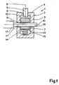
- a connection terminal 1 for electrical power equipment (not shown) comprises a cage 2 which forms a closed side wall 3 which surrounds a cage housing 4.
- a screw 5 is screwed through the side wall 3 of the cage 2 so that its internal end 6 is located in the cage housing 4.
- a movable contact piece 7 is housed in the cage housing 4 so as to being able to move laterally in the cage housing 4, this movement taking place in a direction parallel to the longitudinal axis 8 of the screw 5.
- the movable contact piece 7 comprises a hole 9 substantially in its central part, this hole being preferably cylindrical and being oriented so that its longitudinal axis 10 is substantially perpendicular to the longitudinal axis 8 of the screw 5.
- a hole 11 is on the other hand formed through the side wall 3 of the cage 2, this hole that can pass right through the entire cage 2, as shown in Figure 1 or can simply pass through one side of the side wall 3 (according to a variant not shown).
- the screw 5 is supported at its internal end 6 against a bearing face 12 of the movable contact piece 7.
- the movable contact piece 7 further comprises a lateral face 13 opposite the contact face 12, c that is to say that the side face 13 is located in the part of the movable contact piece 7 which is the farthest from the screw 5.
- a compression spring 14 is housed between the side face 13 of the contact piece mobile 7 and a bearing face 15 located in the cage housing 4 of the cage 2.
- a shallow recess is provided at the side face 13 and another shallow recess is provided at the face d 'Support 15 so that the compression spring 14 is engaged respectively in one and the other of these two housings to be kept lateral.
- the compression spring 14 permanently pushes the movable contact piece 7 against the screw 5. If the screw 5 is completely screwed, the movable contact piece 7 is moved so that its lateral face 13 is brought closer to the face d support 15 thereby strongly compressing the compression spring 14.
- this gripping force is independent of the action that an installer can make on the screw 5.
- this gripping force can be relatively large because it results from a spring of compression 14 which can be designed to develop a relatively high force.
- a relatively high force of the spring 14 can be easily overcome by actuating the screw 5 so as to screw it into the cage 2 because the screw system is capable of developing a relatively axial force. important from a relatively low tightening torque.
- FIGS. 2 and 3 show another embodiment of a connection terminal according to the invention.
- This terminal 20 comprises a cage 21 which forms a closed side wall 22 which surrounds a cage housing 23.
- a screw 24 is screwed through the side wall 22 of the cage 21 so that its internal end 25 is located at inside the cage housing 23.
- a contact piece 26 is movably mounted inside the cage housing 23 and this movable contact piece 26 has a recess 27.
- a stripped end 16 of a cable 17 can be inserted into the recess 27 of the movable contact piece 26.
- a fixed pad 28, integral with the cage 21, extends partially in the recess 27 of the movable contact piece 26 of such so that the stripped end 16 of the cable 17 is then located between a bearing face 29 of the recess 27 and a fixed contact surface 30 of the fixed area 28.
- the contact surface 29 is directed towards the screw 24 and the fixed contact surface 30 is directed towards the contact surface t 29.
- a compression spring 31 is disposed between the movable contact piece 26 and an internal bearing surface 32 forming part of the cage housing 23.
- the compression spring 31 permanently pushes the movable contact piece 26 in the direction of the screw 24 and, when the screw 24 is completely screwed into the cage 21, the movable contact piece 26 is moved from so as to compress the compression spring 31 and in such a way that the contact surface 29 of the movable contact piece 26 and the fixed contact surface 30 of the fixed pad 28 are relatively spaced from one another in order to being able to introduce with a certain clearance the stripped end 16 of the cable 17. Then, by unscrewing the screw 24 so that it is moved towards the outside of the cage 21, the corresponding movement of the contact piece is caused mobile 26 under the action of the compression spring 31 and this causes the stripped end 16 of the cable to be pinched between the surfaces 29 and 30.
- the part which is fixed relative to the electrical equipment is the fixed surface 28 whereas in the first embodiment shown in FIG. 1, the fixed part with respect to the electrical equipment is the cage 2.
- This stop means can be constituted for example by a widening of the internal end 6 (or 25) of the screw.
- the screw 5 may advantageously include a display so that the installer can see whether it is screwed on or unscrewed.
- This display element can be constituted, for example, by a color mark located in a region of the screw which is visible when the screw is unscrewed, that is to say when the screw is in the position moved outward relative to to the cage and invisible when the screw is screwed, that is to say moved towards the inside of the cage.
Landscapes
- Connections By Means Of Piercing Elements, Nuts, Or Screws (AREA)
- Connections Arranged To Contact A Plurality Of Conductors (AREA)
- Switch Cases, Indication, And Locking (AREA)
Applications Claiming Priority (2)
| Application Number | Priority Date | Filing Date | Title |
|---|---|---|---|
| FR9211985 | 1992-10-05 | ||
| FR9211985A FR2696584B1 (fr) | 1992-10-05 | 1992-10-05 | Borne de raccordement pour appareillage électrique de puissance. |
Publications (2)
| Publication Number | Publication Date |
|---|---|
| EP0592336A1 true EP0592336A1 (de) | 1994-04-13 |
| EP0592336B1 EP0592336B1 (de) | 1997-07-16 |
Family
ID=9434302
Family Applications (1)
| Application Number | Title | Priority Date | Filing Date |
|---|---|---|---|
| EP19930420388 Expired - Lifetime EP0592336B1 (de) | 1992-10-05 | 1993-09-29 | Anschlussklemme für Elektrogeräte |
Country Status (3)
| Country | Link |
|---|---|
| EP (1) | EP0592336B1 (de) |
| DE (1) | DE69312202T2 (de) |
| FR (1) | FR2696584B1 (de) |
Cited By (3)
| Publication number | Priority date | Publication date | Assignee | Title |
|---|---|---|---|---|
| EP0769827A1 (de) * | 1995-10-18 | 1997-04-23 | Pacesetter AB | Anschlussbefestigungsstecker |
| US8987619B2 (en) | 2010-07-28 | 2015-03-24 | Siemens Aktiengesellschaft | Terminal assembly for a power switch in tension spring technology |
| US11515654B2 (en) | 2020-05-06 | 2022-11-29 | Technetix B.V. | Electrical connector with rotatable biasing member |
Families Citing this family (5)
| Publication number | Priority date | Publication date | Assignee | Title |
|---|---|---|---|---|
| FR2798514B1 (fr) * | 1999-09-15 | 2001-11-02 | Schneider Electric Ind Sa | Borne de raccordement a cage elastique |
| DE19962289A1 (de) * | 1999-12-23 | 2001-06-28 | Abb Patent Gmbh | Anschlussklemmenanordnung für ein elektrisches Installationsgerät |
| FR2997237B1 (fr) | 2012-10-23 | 2014-11-21 | Schneider Electric Ind Sas | Cage elastique pour borne de raccordement et borne comportant une telle cage |
| DE202016102669U1 (de) * | 2016-05-19 | 2017-08-22 | Würth Elektronik eiSos Gmbh & Co. KG | Kontaktierungsvorrichtung zur elektrischen Energieübertragung zu einer Leiterplatte |
| DE102023000390B3 (de) | 2023-02-08 | 2024-02-22 | Sew-Eurodrive Gmbh & Co Kg | Anschlussvorrichtung für einen elektrischen Leiter und Kontaktierungseinheit |
Citations (5)
| Publication number | Priority date | Publication date | Assignee | Title |
|---|---|---|---|---|
| DE1212612B (de) * | 1957-02-28 | 1966-03-17 | Josef Eisert | Schaltanlagen-Reihenklemmen |
| FR1534779A (fr) * | 1967-06-02 | 1968-08-02 | Wago Kontakttechnik Gmbh | Serre-fil de sécurité pour conducteurs électriques |
| DE2248189B1 (de) * | 1972-09-30 | 1974-04-04 | Phoenix Elek Zitaetsgesellscha | Elektrische Verbindungsklemme |
| EP0141086A1 (de) * | 1983-09-13 | 1985-05-15 | Square D Starkstrom GmbH | Anschlussklemme für Niederspannungsanlage, insbesondere Schaltgeräte |
| DE3406081A1 (de) * | 1984-02-20 | 1985-08-22 | Siemens AG, 1000 Berlin und 8000 München | Federdruckklemme fuer elektrische leiter |
-
1992
- 1992-10-05 FR FR9211985A patent/FR2696584B1/fr not_active Expired - Fee Related
-
1993
- 1993-09-29 EP EP19930420388 patent/EP0592336B1/de not_active Expired - Lifetime
- 1993-09-29 DE DE1993612202 patent/DE69312202T2/de not_active Expired - Fee Related
Patent Citations (5)
| Publication number | Priority date | Publication date | Assignee | Title |
|---|---|---|---|---|
| DE1212612B (de) * | 1957-02-28 | 1966-03-17 | Josef Eisert | Schaltanlagen-Reihenklemmen |
| FR1534779A (fr) * | 1967-06-02 | 1968-08-02 | Wago Kontakttechnik Gmbh | Serre-fil de sécurité pour conducteurs électriques |
| DE2248189B1 (de) * | 1972-09-30 | 1974-04-04 | Phoenix Elek Zitaetsgesellscha | Elektrische Verbindungsklemme |
| EP0141086A1 (de) * | 1983-09-13 | 1985-05-15 | Square D Starkstrom GmbH | Anschlussklemme für Niederspannungsanlage, insbesondere Schaltgeräte |
| DE3406081A1 (de) * | 1984-02-20 | 1985-08-22 | Siemens AG, 1000 Berlin und 8000 München | Federdruckklemme fuer elektrische leiter |
Cited By (3)
| Publication number | Priority date | Publication date | Assignee | Title |
|---|---|---|---|---|
| EP0769827A1 (de) * | 1995-10-18 | 1997-04-23 | Pacesetter AB | Anschlussbefestigungsstecker |
| US8987619B2 (en) | 2010-07-28 | 2015-03-24 | Siemens Aktiengesellschaft | Terminal assembly for a power switch in tension spring technology |
| US11515654B2 (en) | 2020-05-06 | 2022-11-29 | Technetix B.V. | Electrical connector with rotatable biasing member |
Also Published As
| Publication number | Publication date |
|---|---|
| EP0592336B1 (de) | 1997-07-16 |
| FR2696584B1 (fr) | 1994-12-02 |
| DE69312202D1 (de) | 1997-08-21 |
| FR2696584A1 (fr) | 1994-04-08 |
| DE69312202T2 (de) | 1998-01-02 |
Similar Documents
| Publication | Publication Date | Title |
|---|---|---|
| EP2071677B1 (de) | Anschluss an Anti-Entriegelungssysteme | |
| BE1004372A3 (fr) | Dispositif d'extraction d'une fiche de courant electrique. | |
| EP0592336B1 (de) | Anschlussklemme für Elektrogeräte | |
| CA2373092C (fr) | Douille de securite | |
| FR2534744A1 (fr) | Dispositif de connexion pour conducteur electrique | |
| EP3487006A1 (de) | Elektrisches system, das ein elektrogerät und ein auswechselbares verbindungsmodul umfasst | |
| EP2624365B1 (de) | Elektrische Anschlussklemme | |
| EP0562909B1 (de) | Anschlussklemmen für Drehstromgenerator eines Fahrzeuges | |
| EP1568109B1 (de) | Elektrischer Kontakt mit elastischer Rückstellvorrichtung und elektrischer Verbindungsteil mit mindestens einem solchen Kontakt | |
| EP3190664B1 (de) | Elektrogerät mit anschlussklemme, die mit einem klemmkäfig aus nicht-magnetischem material ausgestattet ist | |
| EP1950858B1 (de) | Befestigungsvorrichtung für Installationsgeräte mittels Krallen | |
| EP1672740B1 (de) | Schnellverbindungsanschlussklemme für Schalter und Steckdosen | |
| BE1012574A6 (fr) | Systeme de transmission comprenant un dispositif de detection de rupture de la courroie de transmission, en particulier de la courroie de transmission entre le vilebrequin et l'arbre a cames d'un moteur. | |
| FR2529719A1 (fr) | Dispositif de securite par verrouillage pour prise de courant | |
| EP4210182B1 (de) | Elektrische buchse, elektrische baugruppe mit einer solchen buchse und einer elektrischen lampe und verfahren zum zusammenbau einer solchen anordnung | |
| EP2849286A1 (de) | Klemme mit doppeltem elektrischem Anschlusssystem, insbesondere für ein elektrisches Niedrigspannungs-Schutzgerät, und eine solche Klemme umfassendes Gerät | |
| FR3001836A1 (fr) | Dispositif de fixation d'un appareillage electrique sur une paroi et procede de deconnexion associe | |
| FR2688350A1 (fr) | Dispositif de connexion electrique et plus particulierement connecteur de charge. | |
| FR2910183A1 (fr) | Contact electrique securise | |
| FR2774516A1 (fr) | Dispositif de verrouillage et de deverrouillage d'un connecteur raccorde a un cable a plusieurs conducteurs, par rapport a une embase | |
| FR2829870A1 (fr) | Sectionneur a fusible comprenant un porte-fusible et un element de commande pour un circuit de securite | |
| FR2824191A3 (fr) | Fiche electrique male avec moyen d'extraction par rapport a une fiche electrique femelle | |
| FR2503941A1 (fr) | Dispositif de connexion electrique souple par cable refroidi par eau | |
| FR2806216A1 (fr) | Dispositif de connexion rapide d'un cable a une borne d'une source d'alimentation en energie electrique | |
| EP0949722A1 (de) | Elektrischer Niederspannungsverbinder |
Legal Events
| Date | Code | Title | Description |
|---|---|---|---|
| PUAI | Public reference made under article 153(3) epc to a published international application that has entered the european phase |
Free format text: ORIGINAL CODE: 0009012 |
|
| AK | Designated contracting states |
Kind code of ref document: A1 Designated state(s): BE DE ES GB IT NL |
|
| 17P | Request for examination filed |
Effective date: 19940921 |
|
| RAP1 | Party data changed (applicant data changed or rights of an application transferred) |
Owner name: SCHNEIDER ELECTRIC SA |
|
| 17Q | First examination report despatched |
Effective date: 19951113 |
|
| GRAG | Despatch of communication of intention to grant |
Free format text: ORIGINAL CODE: EPIDOS AGRA |
|
| GRAH | Despatch of communication of intention to grant a patent |
Free format text: ORIGINAL CODE: EPIDOS IGRA |
|
| GRAH | Despatch of communication of intention to grant a patent |
Free format text: ORIGINAL CODE: EPIDOS IGRA |
|
| GRAA | (expected) grant |
Free format text: ORIGINAL CODE: 0009210 |
|
| AK | Designated contracting states |
Kind code of ref document: B1 Designated state(s): BE DE ES GB IT NL |
|
| PG25 | Lapsed in a contracting state [announced via postgrant information from national office to epo] |
Ref country code: NL Free format text: LAPSE BECAUSE OF FAILURE TO SUBMIT A TRANSLATION OF THE DESCRIPTION OR TO PAY THE FEE WITHIN THE PRESCRIBED TIME-LIMIT Effective date: 19970716 Ref country code: IT Free format text: LAPSE BECAUSE OF FAILURE TO SUBMIT A TRANSLATION OF THE DESCRIPTION OR TO PAY THE FEE WITHIN THE PRE;WARNING: LAPSES OF ITALIAN PATENTS WITH EFFECTIVE DATE BEFORE 2007 MAY HAVE OCCURRED AT ANY TIME BEFORE 2007. THE CORRECT EFFECTIVE DATE MAY BE DIFFERENT FROM THE ONE RECORDED.SCRIBED TIME-LIMIT Effective date: 19970716 Ref country code: GB Effective date: 19970716 Ref country code: ES Free format text: THE PATENT HAS BEEN ANNULLED BY A DECISION OF A NATIONAL AUTHORITY Effective date: 19970716 |
|
| REF | Corresponds to: |
Ref document number: 69312202 Country of ref document: DE Date of ref document: 19970821 |
|
| PG25 | Lapsed in a contracting state [announced via postgrant information from national office to epo] |
Ref country code: BE Free format text: LAPSE BECAUSE OF NON-PAYMENT OF DUE FEES Effective date: 19970930 |
|
| NLV1 | Nl: lapsed or annulled due to failure to fulfill the requirements of art. 29p and 29m of the patents act | ||
| GBV | Gb: ep patent (uk) treated as always having been void in accordance with gb section 77(7)/1977 [no translation filed] |
Effective date: 19970716 |
|
| BERE | Be: lapsed |
Owner name: S.A. SCHNEIDER ELECTRIC Effective date: 19970930 |
|
| PLBE | No opposition filed within time limit |
Free format text: ORIGINAL CODE: 0009261 |
|
| STAA | Information on the status of an ep patent application or granted ep patent |
Free format text: STATUS: NO OPPOSITION FILED WITHIN TIME LIMIT |
|
| 26N | No opposition filed | ||
| PGFP | Annual fee paid to national office [announced via postgrant information from national office to epo] |
Ref country code: DE Payment date: 20000912 Year of fee payment: 8 |
|
| PG25 | Lapsed in a contracting state [announced via postgrant information from national office to epo] |
Ref country code: DE Free format text: LAPSE BECAUSE OF NON-PAYMENT OF DUE FEES Effective date: 20020501 |