EP0592350A1 - Fenêtres résistantes aux explosions - Google Patents
Fenêtres résistantes aux explosions Download PDFInfo
- Publication number
- EP0592350A1 EP0592350A1 EP93630067A EP93630067A EP0592350A1 EP 0592350 A1 EP0592350 A1 EP 0592350A1 EP 93630067 A EP93630067 A EP 93630067A EP 93630067 A EP93630067 A EP 93630067A EP 0592350 A1 EP0592350 A1 EP 0592350A1
- Authority
- EP
- European Patent Office
- Prior art keywords
- locking
- stile
- elements
- sash
- blast resistant
- Prior art date
- Legal status (The legal status is an assumption and is not a legal conclusion. Google has not performed a legal analysis and makes no representation as to the accuracy of the status listed.)
- Withdrawn
Links
- 238000006073 displacement reaction Methods 0.000 claims abstract description 26
- 230000005540 biological transmission Effects 0.000 claims abstract description 13
- 230000003014 reinforcing effect Effects 0.000 claims description 8
- 238000007789 sealing Methods 0.000 claims description 5
- 239000007789 gas Substances 0.000 claims description 3
- 230000001473 noxious effect Effects 0.000 claims description 3
- 239000000470 constituent Substances 0.000 claims description 2
- 239000000428 dust Substances 0.000 claims description 2
- 210000003141 lower extremity Anatomy 0.000 claims description 2
- 210000001364 upper extremity Anatomy 0.000 claims description 2
- 230000015572 biosynthetic process Effects 0.000 claims 1
- 230000002265 prevention Effects 0.000 claims 1
- 230000008878 coupling Effects 0.000 description 5
- 238000010168 coupling process Methods 0.000 description 5
- 238000005859 coupling reaction Methods 0.000 description 5
- 241001074085 Scophthalmus aquosus Species 0.000 description 1
- 229910000831 Steel Inorganic materials 0.000 description 1
- 239000004411 aluminium Substances 0.000 description 1
- 229910052782 aluminium Inorganic materials 0.000 description 1
- XAGFODPZIPBFFR-UHFFFAOYSA-N aluminium Chemical compound [Al] XAGFODPZIPBFFR-UHFFFAOYSA-N 0.000 description 1
- 238000005452 bending Methods 0.000 description 1
- 238000010276 construction Methods 0.000 description 1
- 238000004880 explosion Methods 0.000 description 1
- 230000037431 insertion Effects 0.000 description 1
- 238000003780 insertion Methods 0.000 description 1
- 230000014759 maintenance of location Effects 0.000 description 1
- 229910052751 metal Inorganic materials 0.000 description 1
- 239000002184 metal Substances 0.000 description 1
- 230000002787 reinforcement Effects 0.000 description 1
- 125000006850 spacer group Chemical group 0.000 description 1
- 239000010959 steel Substances 0.000 description 1
Images
Classifications
-
- E—FIXED CONSTRUCTIONS
- E05—LOCKS; KEYS; WINDOW OR DOOR FITTINGS; SAFES
- E05C—BOLTS OR FASTENING DEVICES FOR WINGS, SPECIALLY FOR DOORS OR WINDOWS
- E05C9/00—Arrangements of simultaneously actuated bolts or other securing devices at well-separated positions on the same wing
- E05C9/06—Arrangements of simultaneously actuated bolts or other securing devices at well-separated positions on the same wing with three or more sliding bars
- E05C9/063—Arrangements of simultaneously actuated bolts or other securing devices at well-separated positions on the same wing with three or more sliding bars extending along three or more sides of the wing or frame
Definitions
- the present invention is in the field of casement windows and more specifically it concerns a blast resistant framework for casement windows.
- casement window of the kind specified comprises a rectangular framework consisting of a frame anchored within an opening in a wall and a sash swingably mounted thereon with locking means preventing unintended opening thereof.
- casement windows are not normally designed to resist blasts caused, for example, by an explosion, although the frame may remain firmly anchored to the wall and the window pane itself may be blast resistant. In most cases the result of a blast will only be a slight deformation of the frame, but the sash itself may be completely detached therefrom.
- This situation is particularly undesirable where the window must remain effectively sealed so as to prevent the entry of noxious gases.
- a rectangular, blast resistant framework for a casement window comprising: a window sash pivotally mounted at a hanging stile thereof with respect to a hanging jamb of a fixed rectangular frame of the framework; a rotary locking mechanism mounted on a shutting stile of the sash, having a rotary handle and an engaging tongue projecting out of said shutting stile and displaceable along said shutting stile upon rotation of the rotary handle by a displacement stroke of at least about 25 mm; first, second and third elongated carrier members respectively and articulatedly mounted on said shutting stile and top and bottom rails of said sash so as to be displaceable therealong for a distance substantially equal to said displacement stroke, said first carrier member being engaged by said engaging tongue so as to be displaceable therewith; upper and lower resiliently bendable transmission strips respectively and displaceably mounted about a pair of corners of said sash adjacent said shutting stile and respectively coupled at one pair of ends thereof to upper and lower extremities of said first carrier
- the blast resistant framework in accordance with the invention is readily suitable for instalment in an existing opening in a wall in place of a conventional casement framework.
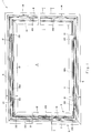
- Figs. 1 and 2 of the drawings illustrate a rectangular framework 1 for a blast resistant window pane 2.
- the framework which can be formed of a light metal such as aluminium, comprises an outer frame 3 which is anchored by means of bolts 4 within a corresponding rectangular aperture formed in a wall.
- the frame 3 consists of an upper frame head 5, a lower frame sill 6, a side shutting jamb 7 and a side hanging jamb 8.
- the framework 1 furthermore comprises a window sash 9 which consists of profiled top rail 10, bottom rail 11, shutting stile 12 and hanging stile 13.
- the window sash 9 is pivotally mounted with respect to the outer frame 3 by means of hinges 14 secured respectively to the hanging jamb 8 and the hanging stile 13.
- the shutting and hanging stiles 12 and 13 are respectively formed with inwardly directed pairs of reinforcing flanges 15 and 16 designed to receive the end portions of the pane 2, the edges of which bear against spacer elements 17 secured to the stiles 12 and 13.
- the top and bottom rails 10 and 11 respectively are also provided with such reinforcing flanges.
- the top and bottom rails 10 and 11 of the window sash 9 have slidably secured thereto respective upper and lower carrier members 18a and 18b whilst the shutting stile 12 has slidably secured thereto an upright carrier member 19.
- Mounted on the carrier members 18a and 18b and the upright carrier member 19 are spaced apart locking elements 20 designed to be releasably engageable in corresponding respectively juxtaposed receiving elements 21, secured to the adjacent upper frame head 5, lower frame sill 6 and side shutting jamb 7.
- the upright carrier member 19 is coupled at its uppermost end to an adjacent end of the upper carrier member 18a by means of an upper, resiliently displaceable transmission member 22, whilst the lower end of the upright carrier member 19 is coupled to the adjacent end of the lower carrier member 18b by means of a lower, resiliently displaceable transmission member 23.
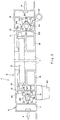
- the upright carrier member 19 is formed at its longitudinal edges with respective elongated slots 24 adapted to receive corresponding flanges 25 formed integrally with the adjacent shutting stile 12. In this way, the upright carrier member 19 is slidably displaceable on and with respect to the shutting stile 12. Extending along the length of the upright carrier member 19 is an elongated dovetailed groove 26 in which are slidably fitted locking elements 20 formed with corresponding flanges which slidably fit within the dovetailed groove 26. The locking elements 20 are fixed in any desired position along the length of the upright carrier element by means of fixing screws 27.
- a rotary locking mechanism 29 is mounted on the shutting stile 12 and is provided with a rotary handle 30 and an engaging tongue 31 projecting out of the shutting stile and into the slot 28.
- the rotary locking mechanism 29 is such that rotary movement of the handle 30 is converted into a linear translational movement of the engaging tongue 31 which is imparted to the upright carrier member 19.
- the displacement stroke of the engagement tongue 31, and therefore the linear displacement of the upright carrier member 19 upon rotation of the handle 30, is at least about 25 mm.
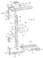
- the upright carrier member 19 is coupled to the carrier members 18a and 18b by means of upper and lower resiliently displaceable transmission members 22, 23. As shown in Fig.
- the planar coupling element 32 is designed to fit into a corresponding recessed end portion 34 of the upright carrier member 19 with the stud 33 fitting within an aperture 35 formed in the end portion 34.
- the elongated resiliently displaceable transmission member 22 extends through a right-angled rigid frame 36 which bounds the adjacent corners of the shutting stile 12 and the top rail 10 of the window sash 9 and is secured thereto by means of securing bolts 37.
- the end of the transmission member 22 remote from the coupling element 32 is formed with a downwardly depending coupling stud 38 which fits into an aperture 39 formed in an end portion 40 of the upper longitudinal carrier member 18a.
- the lower end of the upright carrier member 19 is coupled to the lower resiliently displaceable transmission member 23 (via a corresponding stud and aperture 41 and 42).
- the member 23 extends through a right-angled rigid frame 43 secured to adjacent corners of the shutting stile 12 and bottom rail 11.
- the lower transmission member 23 is, in its turn, coupled to the lower carrier member 18b via a stud and hole arrangement 44 and 45.
- the receiving elements 21 are slidably mounted in profiled portions of the side shutting jamb 7 and the upper frame head 5 and the lower frame sill 6.
- the locking elements 20 are fixed in position on their respective carrier members so as closely to adjoin the positioning of the receiving elements 21 on the adjacent frame.
- the upright carrier member 19 is displaced downwardly in the direction of the arrow 47 and the locking elements 20 attached to the upright carrier member are also displaced downwardly and into their adjoining receiving elements 21 so as to be effectively locked thereby.
- the upper resiliently displaceable transmission member 22 is also displaced downwardly and causes a transverse movement in the direction of the arrow 48 of the upper carrier member 18a, with a consequent movement of the locking elements 20 associated with the upper carrier member 18a into their adjoining receiving elements 21, thereby effectively locking these elements 20 within the receiving elements 21.
- the downward movement of the upright carrier member 19 results in a downward displacement of the lower resiliently displaceable transmission member 23 causing a transverse movement to the lower carrier member 18b in the direction of the arrow 47, with a consequent displacement of the associated locking elements 20 into their adjacent receiving elements.
- the window sash is effectively and firmly locked to the window frame by means of a plurality of locking elements and it will be readily seen that the effectiveness of the locking is directly related to the number of locking elements and also to the length thereof, and these lengths are chosen so as to be directly related to the stroke of the carrier elements.
- Opening of the window can be readily effected by rotation of the rotary handle in an anti-clockwise direction.
- the side hanging jamb 8 of the outer frame 3, together with the hanging stile 13 of the window sash 9 are provided with longitudinally spaced apart reinforcing means 49, designed to impart to the hinged sides of the rectangular framework adequate reinforcement against displacement in the event of blast and the like.
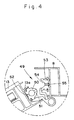
- FIG. 2 and 4 of the drawings shows, on an enlarged scale, one of the reinforcing means 49 seen in Fig. 1 of the drawings. (Fig. 4 shows the means 49 with the window in an open position.)
- the hanging stile 13 is in principle identical in construction with the shutting stile 12 and is formed with inwardly directed flanges 13a which fit into corresponding recesses formed in an elongated locking member 50 having a projecting portion 51.
- the locking member 50 can be slidably positioned with respect to the hanging stile 13 and be fixed in the required position by a fixing screw 52.
- each elongated locking member 50 Juxtaposed with respect to each elongated locking member 50 is an elongated receiving member 53 formed with a receiving recess 54 into which can matingly fit the projecting portion 51.
- the elongated receiving member 53 is formed on either side thereof with elongated slots which receive inwardly directed flanges formed integrally with the hanging jamb 8.
- the receiving member 53 is slidably positioned with respect to the hanging jamb and is located in the required position opposite the locking member 50 by means of a positioning screw 55.
- the blast resistant protection afforded by the provision of the locking elements 20 and receiving elements 21, associated as they are with the hanging jamb 8 and hanging stile 13, the upper frame head 5 and the top rail 10, and the lower frame sill 6 and the bottom rail 11 on the one hand and, on the other hand, the elongated locking members 50 and elongated receiving members 53 associated as they are with the hanging jamb 8 and the hanging stile 13, is largely a function of the numbers of the elements and members, the longitudinal extent thereof and their cross-sectional dimensions.
- the longitudinal extents of the locking and receiving elements 20 and 21 is clearly closely related to the stroke of the engaging tongue 31 upon rotation of the rotary handle 30, which stroke is transmitted to the carrier members 18a, 18b and 19.
- the length of the stroke effectively determines the degree of insertion of each locking element into its corresponding receiving element.
- the spacing between the adjacent locking and receiving elements is minimal, then it can be ensured that the longitudinal extent of the locking elements correspond substantially to the stroke.
- a blast resistant framework as just described is effective against distortion and/or detachment with blasts corresponding to one atmosphere pressure (14.2 PSI).
- the rectangular framework 1 just described can be provided in a known manner with effective sealing means (not shown) to prevent ingress or egress of air, noxious gases and dust.
- the framework just described being provided with the reinforced locking mechanism, provides substantially increased protection against detachment of the sash from the frame in the event of blast.
- blast resistant framework just described can be readily installed into any existing window opening.
Landscapes
- Engineering & Computer Science (AREA)
- Mechanical Engineering (AREA)
- Wing Frames And Configurations (AREA)
Applications Claiming Priority (2)
| Application Number | Priority Date | Filing Date | Title |
|---|---|---|---|
| IL103168 | 1992-09-15 | ||
| IL10316892A IL103168A (en) | 1992-09-15 | 1992-09-15 | Blast resistant windows |
Publications (1)
| Publication Number | Publication Date |
|---|---|
| EP0592350A1 true EP0592350A1 (fr) | 1994-04-13 |
Family
ID=11064034
Family Applications (1)
| Application Number | Title | Priority Date | Filing Date |
|---|---|---|---|
| EP93630067A Withdrawn EP0592350A1 (fr) | 1992-09-15 | 1993-09-14 | Fenêtres résistantes aux explosions |
Country Status (2)
| Country | Link |
|---|---|
| EP (1) | EP0592350A1 (fr) |
| IL (1) | IL103168A (fr) |
Cited By (3)
| Publication number | Priority date | Publication date | Assignee | Title |
|---|---|---|---|---|
| EP0845566A3 (fr) * | 1996-12-02 | 1999-01-13 | Exacta-Fenster-Bau GmbH | Unité de battant |
| FR2772417A1 (fr) * | 1997-12-16 | 1999-06-18 | Saga Distribution Survitrage | Survitrage ouvrant a verrouillage |
| EP0943769A3 (fr) * | 1998-03-20 | 2003-11-05 | W. HAUTAU GmbH | Système de verrouillage centralisé à montage simple |
Families Citing this family (1)
| Publication number | Priority date | Publication date | Assignee | Title |
|---|---|---|---|---|
| IL123980A (en) | 1998-04-07 | 2000-10-31 | Arpal Aluminum Ltd | Blast resistant window framework and elements thereof |
Citations (4)
| Publication number | Priority date | Publication date | Assignee | Title |
|---|---|---|---|---|
| FR2073131A5 (fr) * | 1970-01-08 | 1971-09-24 | Reuschenbach J | |
| FR2237041A1 (en) * | 1973-07-09 | 1975-02-07 | Ver Baubeschlag Gretsch Co | Lock for tilting and rotating frames of windows and doors - has actuating rod in circumferential groove of frame for holding locking pins |
| FR2358535A1 (fr) * | 1976-07-15 | 1978-02-10 | Syco Prod Entwicklungs Gmbh | Fermeture centrale pour portes et fenetres |
| FR2529247A1 (fr) * | 1982-06-24 | 1983-12-30 | Frank Gmbh Wilh | Dispositif de fermeture a tringle d'entrainement pour le battant recouvert d'une fenetre ou d'une porte a deux battants sans montant central |
-
1992
- 1992-09-15 IL IL10316892A patent/IL103168A/en not_active IP Right Cessation
-
1993
- 1993-09-14 EP EP93630067A patent/EP0592350A1/fr not_active Withdrawn
Patent Citations (4)
| Publication number | Priority date | Publication date | Assignee | Title |
|---|---|---|---|---|
| FR2073131A5 (fr) * | 1970-01-08 | 1971-09-24 | Reuschenbach J | |
| FR2237041A1 (en) * | 1973-07-09 | 1975-02-07 | Ver Baubeschlag Gretsch Co | Lock for tilting and rotating frames of windows and doors - has actuating rod in circumferential groove of frame for holding locking pins |
| FR2358535A1 (fr) * | 1976-07-15 | 1978-02-10 | Syco Prod Entwicklungs Gmbh | Fermeture centrale pour portes et fenetres |
| FR2529247A1 (fr) * | 1982-06-24 | 1983-12-30 | Frank Gmbh Wilh | Dispositif de fermeture a tringle d'entrainement pour le battant recouvert d'une fenetre ou d'une porte a deux battants sans montant central |
Cited By (4)
| Publication number | Priority date | Publication date | Assignee | Title |
|---|---|---|---|---|
| EP0845566A3 (fr) * | 1996-12-02 | 1999-01-13 | Exacta-Fenster-Bau GmbH | Unité de battant |
| FR2772417A1 (fr) * | 1997-12-16 | 1999-06-18 | Saga Distribution Survitrage | Survitrage ouvrant a verrouillage |
| EP0943769A3 (fr) * | 1998-03-20 | 2003-11-05 | W. HAUTAU GmbH | Système de verrouillage centralisé à montage simple |
| DE19912839B4 (de) * | 1998-03-20 | 2010-07-29 | Hautau Gmbh | Leicht montierbarer Zentralverschluß für Flügel |
Also Published As
| Publication number | Publication date |
|---|---|
| IL103168A (en) | 1994-04-12 |
Similar Documents
| Publication | Publication Date | Title |
|---|---|---|
| US6502356B2 (en) | Blast resistant window framework and elements thereof | |
| CA2191821C (fr) | Fermeture pour fenetre | |
| US2916112A (en) | Metal window construction | |
| CA2196492C (fr) | Fermeture pour ensembles de chassis de fenetre coulissante et d'encadrement de porte | |
| US6293049B1 (en) | Method and apparatus for installing a window assembly | |
| US6311439B1 (en) | Window frame | |
| US3711995A (en) | Building structure | |
| US3879894A (en) | Sliding screen door | |
| US3990196A (en) | Fabricated window construction | |
| US6415565B1 (en) | Storm rail for sliding door | |
| CA2574221A1 (fr) | Cadre de fenetre semi-amovible | |
| US2704866A (en) | Sliding closure | |
| WO1996012859A1 (fr) | Procede et appareil pour installer un panneau de fenetre coulissant dans un cadre | |
| EP0592350A1 (fr) | Fenêtres résistantes aux explosions | |
| US3691713A (en) | Panel mounting apparatus | |
| CA2289789C (fr) | Element de renforcement pour le basculement d'un systeme de fenetre de type chassis | |
| US3905154A (en) | Building structure | |
| US2643422A (en) | Window construction | |
| GB2227051A (en) | Multi-point window lock | |
| US7533497B2 (en) | Snubber system for windows | |
| US3219100A (en) | Storm window | |
| AU681864B2 (en) | Improvements in and relating to double hung windows | |
| US4047333A (en) | Snap-in keeper for sliding windows, doors and the like | |
| GB2298446A (en) | Frames for apertures in cavity walls | |
| GB2287979A (en) | Espagnolette fasteners |
Legal Events
| Date | Code | Title | Description |
|---|---|---|---|
| PUAI | Public reference made under article 153(3) epc to a published international application that has entered the european phase |
Free format text: ORIGINAL CODE: 0009012 |
|
| AK | Designated contracting states |
Kind code of ref document: A1 Designated state(s): BE DE ES FR GB GR IE IT NL PT |
|
| STAA | Information on the status of an ep patent application or granted ep patent |
Free format text: STATUS: THE APPLICATION IS DEEMED TO BE WITHDRAWN |
|
| 18D | Application deemed to be withdrawn |
Effective date: 19941014 |