EP0592355A2 - Dispositif de préhension d'articles - Google Patents
Dispositif de préhension d'articles Download PDFInfo
- Publication number
- EP0592355A2 EP0592355A2 EP93710019A EP93710019A EP0592355A2 EP 0592355 A2 EP0592355 A2 EP 0592355A2 EP 93710019 A EP93710019 A EP 93710019A EP 93710019 A EP93710019 A EP 93710019A EP 0592355 A2 EP0592355 A2 EP 0592355A2
- Authority
- EP
- European Patent Office
- Prior art keywords
- sensor
- gripping
- piece goods
- size
- elements
- Prior art date
- Legal status (The legal status is an assumption and is not a legal conclusion. Google has not performed a legal analysis and makes no representation as to the accuracy of the status listed.)
- Granted
Links
Images



Classifications
-
- B—PERFORMING OPERATIONS; TRANSPORTING
- B65—CONVEYING; PACKING; STORING; HANDLING THIN OR FILAMENTARY MATERIAL
- B65G—TRANSPORT OR STORAGE DEVICES, e.g. CONVEYORS FOR LOADING OR TIPPING, SHOP CONVEYOR SYSTEMS OR PNEUMATIC TUBE CONVEYORS
- B65G47/00—Article or material-handling devices associated with conveyors; Methods employing such devices
- B65G47/74—Feeding, transfer, or discharging devices of particular kinds or types
- B65G47/90—Devices for picking-up and depositing articles or materials
- B65G47/91—Devices for picking-up and depositing articles or materials incorporating pneumatic, e.g. suction, grippers
-
- B—PERFORMING OPERATIONS; TRANSPORTING
- B25—HAND TOOLS; PORTABLE POWER-DRIVEN TOOLS; MANIPULATORS
- B25B—TOOLS OR BENCH DEVICES NOT OTHERWISE PROVIDED FOR, FOR FASTENING, CONNECTING, DISENGAGING, OR HOLDING
- B25B11/00—Work holders not covered by any preceding group in the subclass, e.g. magnetic work holders, vacuum work holders
- B25B11/005—Vacuum work holders
-
- B—PERFORMING OPERATIONS; TRANSPORTING
- B66—HOISTING; LIFTING; HAULING
- B66C—CRANES; LOAD-ENGAGING ELEMENTS OR DEVICES FOR CRANES, CAPSTANS, WINCHES, OR TACKLES
- B66C1/00—Load-engaging elements or devices attached to lifting or lowering gear of cranes or adapted for connection therewith for transmitting lifting forces to articles or groups of articles
- B66C1/02—Load-engaging elements or devices attached to lifting or lowering gear of cranes or adapted for connection therewith for transmitting lifting forces to articles or groups of articles by suction means
- B66C1/0237—Multiple lifting units; More than one suction area
- B66C1/0243—Separate cups
-
- B—PERFORMING OPERATIONS; TRANSPORTING
- B66—HOISTING; LIFTING; HAULING
- B66C—CRANES; LOAD-ENGAGING ELEMENTS OR DEVICES FOR CRANES, CAPSTANS, WINCHES, OR TACKLES
- B66C1/00—Load-engaging elements or devices attached to lifting or lowering gear of cranes or adapted for connection therewith for transmitting lifting forces to articles or groups of articles
- B66C1/02—Load-engaging elements or devices attached to lifting or lowering gear of cranes or adapted for connection therewith for transmitting lifting forces to articles or groups of articles by suction means
- B66C1/0256—Operating and control devices
-
- B—PERFORMING OPERATIONS; TRANSPORTING
- B66—HOISTING; LIFTING; HAULING
- B66C—CRANES; LOAD-ENGAGING ELEMENTS OR DEVICES FOR CRANES, CAPSTANS, WINCHES, OR TACKLES
- B66C1/00—Load-engaging elements or devices attached to lifting or lowering gear of cranes or adapted for connection therewith for transmitting lifting forces to articles or groups of articles
- B66C1/02—Load-engaging elements or devices attached to lifting or lowering gear of cranes or adapted for connection therewith for transmitting lifting forces to articles or groups of articles by suction means
- B66C1/0281—Rectangular or square shape
Definitions
- the invention relates to a device for gripping piece goods, in particular cuboid objects, such as outer packaging or book packs.
- a gripping area is adapted to the general cargo.
- a device for gripping in which a gripping area forms a suction surface.
- This gripping area has circular suction elements which are connected to a vacuum system.
- the gripping range is variable because sensor elements record the dimensions of the piece goods and activate the corresponding number of suction elements.
- the vacuum system acts on the suction elements in that a suction element valve is motor-controlled by the sensor elements.
- Such a device is used for picking up and storing objects.
- the gripping area is variable in that as many suction elements form a negative pressure as suction cups overlap the object to be transported.
- a gripping area is known from US Pat. No. 4,252,497, which consists of a multiplicity of round suction elements. These suction elements are controlled by valves depending on the size of the piece goods, with sensor elements detecting the size. The control takes place by releasing a valve that connects four suction elements next to each other with the vacuum system.
- German Offenlegungsschrift DE-OS 31 01 864 describes a device, the individual suction elements of which are each controlled by a valve.
- the valve is controlled on the basis of a contact between the piece goods to be picked up and the suction element.
- a resilient sensor element in the form of a pin which is connected directly to the valve, is pressed in the direction of the device. This will release the valve.
- the connection between the vacuum system and the suction element is established.
- Rough surfaces of the piece goods to be gripped are disadvantageous. Due to the small flow cross-sections, these devices are prone to failure. The device is also not able to adjust to the different density of the piece goods, since the fixed cross-section of the valves, the suction elements and the constant spring pressure of the pin allow restricted work.
- a device in which a gripping area is manually adapted to the piece goods.
- the device has a vacuum system which is connected to the outside area via external openings.
- the size of the outer openings is adjusted by a curtain-like slide.
- the slide has a sealing part in the form of a sealing strip in its lower area, while the lower horizontal area of the gripping area is provided with a sealing element in the form of a sealing lip.
- the device can grip piece goods with different sizes and densities.
- the device is intended to independently adjust the gripping area to the individually sized piece goods, which are different in height or width.
- the setting should be quick, the holder should be secure and the gripping should be gentle on the piece goods.
- General cargo according to the invention can be a wide variety of objects. All objects which are in a cuboid outer packaging or which are themselves cuboid are particularly suitable. This makes it possible to make the gripping area planar. This results in the device design, which can certainly be used most extensively. Due to the high packing density and the cheap palletizing, the packaging is particularly suitable as a cuboid.
- a barrel-shaped, concave shape makes sense, especially if it repeats itself periodically. This means that stacks of books with different numbers of books can be gripped, since the convex book spines fit into the recesses in the gripping area.
- the external shape of the piece goods which can be transported in any number, determines what the respective design of the gripping area looks like.
- a replaceable surface of the gripping area is particularly economical. It is also conceivable to mount sealing plates on the gripping area which correspond on the one hand to the shape of the piece goods, but on the other hand are also suitable for adapting to different surfaces of the piece goods within a normal range.
- the term "grasp” encompasses the entire gripping and transport process. Specifically, this means that the gripping area is attached to the piece goods, a contacting of the gripping area on the piece goods by forming the negative pressure.
- the device and general cargo form a transportable unit.
- the device is particularly suitable to be the end piece of a gripper or a transport arm. It is also conceivable for the device to be part of a float or a movable transport system on wheels or on an air cushion. A stationary or restrictedly movable device is also conceivable, the piece goods being moved on conveyor belts, treadmills, wagons, hovercraft or other vehicles (magnetic levitation vehicles).
- the unit of piece goods and device can be moved with the help of a gripper.
- the vacuum system acts directly on the piece goods, since the outer openings are only opened with the piece goods in the gripping area. Air volumes are low.
- the device according to the invention allows both arrangements. It is also possible that the device grips the piece goods laterally or from above.
- the number of channels depends on the size of the piece goods. This will be discussed in a further embodiment.
- the vacuum system should be able to be switched on and off, since the suction process for the piece goods only begins and can be maintained by designing the vacuum system. If the object is to be put down again, the vacuum can be released. It is also conceivable to control the outer openings or inner openings separately in order to bring the vacuum system into effect or to make it ineffective. The build-up and breakdown of the vacuum can be controlled.
- the vacuum can be generated by various known vacuum pumps.
- the sensor elements are probes with a length measurement method based on mechanical contact or, for example, optical light barriers and length measurements. These sensor elements record the size and dimensions of the piece goods.
- the sensor elements expediently have a presetting which is set electronically in accordance with the average size of the piece goods. This reduces the adaptation time of the sensor elements and the time for controlling the outer openings. It is also possible to determine the presetting by measuring cameras or long-distance measuring devices and then to specify the position of the sensor elements.
- the device can have one or two sensor elements operating in parallel. If only one sensor element is used, it makes sense if the device is moved to predetermined positions in a controlled manner by means of circuits. This is very easy when palletizing. Electronic controls are particularly suitable for this. Databases or measuring cameras can help to pre-orient the gripping area in relation to the piece goods during the approach phase.
- An important element of this device are elongated systems, namely the channels, which establish a connection between the vacuum system via the inner opening (s) and the outer region via the outer opening (s).
- the external opening or external openings are controlled either directly or indirectly via the sensor elements.
- Particularly large valve and line cross sections of the vacuum system, the ducts and the inner and outer openings result in a low line resistance.
- the negative pressure is quickly built up in the channels.
- the large cross sections only require a small pressure difference.
- General cargo with high density can easily be held. Clogging of the lines by small particles is not so easy.
- a device according to the invention is advantageous in which the sensor element or elements are essentially cuboid.
- Such cuboid sensor elements adapt themselves to the cuboid outer packaging of the piece goods and cuboid piece goods themselves, as a result of which the accuracy of fit during the scanning process is increased. This avoids quantities of incorrect air, since the sensor element and the gripping area are coordinated with one another.
- a device according to the invention is preferred in which the sensor element (s) lie sealingly on the piece goods.
- the sensor element (s) essentially have a surface facing the piece goods, which is essentially perpendicular to the gripping area.
- the sensor element or sensors are in contact with the piece goods in such a way that they assume the function of a seal arranged laterally from the gripping area.
- the lateral support prevents the piece goods from slipping out of the gripping area.
- This arrangement is supported by the sensor element opposite sealing elements with respect to the gripping area if a sensor element is present. If there are two sensor elements arranged in parallel and working in parallel, the piece goods are detected by the sensor elements on two opposite surfaces.
- the sealing function of the sensor element (s) in the case of multiple gripping cuboid bodies means that joints between the individual items are closed by the pressure acting on the side of the gripping area, thereby avoiding the quantity of incorrect air and also correcting the desired position.
- the sensor element or elements can also be adjusted by moving it in the direction of the piece goods so that they can be gripped safely.
- the position of the piece goods in relation to the gripping area can be corrected by the sensor element or elements.
- a device according to the invention is advantageous in which the sensor element or elements are and essentially are a size sensor or size sensors run perpendicular to the channels and in which (i) the size of the outer opening or (ii) the number of outer openings per channel can be controlled by the size sensor or sensors.
- the task of the size sensor (s) is to control the size of the channels with regard to their effective suction area. Ultimately, whether the channels have a continuous, elongated outer opening or a large number of small outer openings that can be closed and opened one after the other is only a question of individual design. The intention is to enable the channels to be adjusted to the size of the piece goods.
- the outer openings of the channels can be closed at least from one side in the manner of a curtain.
- the curtain can consist of slats that run parallel to the outer opening and are preferably wider than this. This is the case if the channels are separated from each other. If the channels form a common cavity, the curtain can be rectangular and in one piece. If two size sensors are available, two curtain-like locking mechanisms are also required, which limit the gripping area from both sides. As a result, the area relevant to the gripping area can be set in a simple manner. The easy adjustability of the curtain is ensured because the curtain is only pressed onto the guide struts when the negative pressure is built up. The curtain does not need to be closed directly with the sensor part facing the gripping area, rather it makes sense for the curtain to end under the cuboid sensor, since this also fixes the sensor in its position when the negative pressure is built up.
- a further embodiment of the device according to the invention is that the sensor element or elements are a number sensor or number sensors which run essentially parallel to the channels, the number of open inner openings being controllable by the number or sensors.
- This embodiment can be equipped with one or with two number sensors, in the case of two number sensors both lying opposite one another and limiting the gripping range.
- the gripping area is variable in one dimension. In principle, it does not matter whether the height or the width of the gripping area can be changed.
- the device is also suitable for gripping the piece goods laterally or from above.
- a preferred embodiment of the device according to the invention consists of a device in which the size sensor (s) control the gripping area in one dimension and the number sensor (s) in a further second dimension.
- both dimensions are essentially perpendicular to one another.
- the shape of the piece goods may require a different angle between the two dimensions.
- the gripping area can thus be controlled, for example, in width by means of the number sensors and in height by means of the size sensors.
- the number sensors control the number of channels connected to the vacuum system by e.g. Valves or slides, and the size sensors control the size of the outer openings or the number of outer openings per channel by, for example, curtain-like closures or valves.
- the number of locking mechanisms (number slider or curtain-type closure) is also available.
- Another embodiment of the device according to the invention is that the vacuum system is connected to a suction and pressure line and optionally to the surrounding area via controllable valves. This has the advantage that the piece goods can be released quickly from the device.
- a further embodiment detects a device according to the invention in which at least one side of the gripping region has a sealing element which is arranged on the side not occupied by the sensor elements.
- Such sealing elements support the building up of the negative pressure.
- the piece goods are held at the top or bottom by the sealing element, and the piece goods are stabilized in their shape, which is desirable in the case of flexible material, for example printed products.
- sealing element or elements are designed as half gripping element or half gripping elements.
- a number sensor with a gripping element and / or a size sensor with a gripping element each forms a gripper.
- the mechanical functions are supported by electronics and by data processing. This significantly shortens the access time.
- the electronics provide for a pre-orientation of the sensors, so that the sensor elements only have to cover short distances to correctly touch the piece goods.
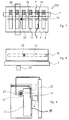
- FIG. 1 shows a device 100, the gripping area 1 of which is characterized by sections A and B.
- A represents the width
- B the height of the gripping area 1.
- the device 100 has six vertical channels 2, which are arranged in parallel. The channels are separated by five webs 3.
- the gripping area 1 is limited at the top by a size sensor 4, which is an elongated, rectangular cuboid.
- the size sensor is arranged in front of the webs, which together with a lower frame 5 and an upper frame 6 form an area to the outside.
- the curtain has slats and has one slat per channel. Each lamella has the width to seal an outer opening.
- FIG. 2 shows the same device seen from the side.
- the device 100 here shows one of the vertical channels 2 in cross section, the cutting plane meeting one of the webs 3 in the center.
- the channels are separated from one another by webs and each have an inner opening 14 (see FIG. 3) to a suction and pressure line 15 connecting all channels.
- the curtain is controlled by the size sensor 4.
- FIG. 3 shows a further view of the same device, the cross section running through one of the outer openings 11. The viewer looks at one of the webs 3, while the other parts of the device are shown in cross section.
- the curtain 7 comes to rest under the size sensor 4, as a result of which the cuboid of the size sensor 4 is also sucked onto the webs 3.
- the size sensor 4 has previously been moved to the piece goods 12 and has been sucked in by the negative pressure. In this way, size sensor 4 and sealing element 13 act as grippers 17.
- the channel has an outer opening 11 on the side facing the outer region 10, the height of which is indicated by the letter C.
- the outside area is partially filled by a piece good 12.
- the general cargo rests on the surface formed by the webs 3 and the lower frame 5 and the upper frame 6. It (the piece goods) is framed at the top by size sensor 4 and at the bottom by a sealing element 13, which is flipped out in the manner of a tongue, and fixed during transport.
- FIG. 4 shows the device 100 taking into account the control of the curtain 7 by the size sensor 4.
- the size sensor slides in a rail 18, two sliders 19 being connected to the size sensor 4 via a size holder 20.
- the size bracket is mechanically coupled to the curtain 7.
- a size motor 21 controls the position of the size sensor and the curtain, the spring 9 developing a counterforce.
- the size sensor When approaching the piece goods 12, the size sensor is pre-oriented. It then moves in the direction of the piece goods by touch. When the size sensor 4 lightly contacts the piece goods 12, the size motor 21 is stopped and locked. However, a slight movement of the size sensor 4 to the piece goods 12 is still necessary due to the suction process.
- FIG. 5 shows a second embodiment 200 which has a number sensor 22 which controls a slide 23 in the suction and pressure line 15.
- the slide limits the suction and pressure line 15 to the right in FIG. 5.
- the vacuum system 16 is effective in this part of the line 15.
- the vacuum system 16 is connected to the channels 2 via the inner openings 14.
- the outer openings 11 of the channels 2 can be seen to the front, the outer openings being separated by the webs 3.
- FIG. 6 shows the device 200 (see FIG. 5) in a longitudinal section, the control mechanism of the number sensor 22 becoming visible.
- the number sensor 22 also slides in a rail, the slider being connected to the number sensor 22 via a number bracket 24.
- the slider and the rail are not shown, but they are designed analogously to FIG. 4.
- the number sensor 22 controls the slide 23 via a device which is double U-shaped or oval, three deflection rollers 25 leading an oval linkage 27, at one end of which the slide 23 is arranged.
- a number motor 26 moves the number sensor 22 in the direction of the piece goods (to the right in FIG. 6). This also moves the slider 23 to the right.
- a spring 28 also provides the counterforce to the number motor 26 in this case.
- FIG. 6 also shows the vacuum system 16, which is connected to the inner opening 14 by the suction and pressure line 15.
- the slider 23 limits the number of open inner openings 14 to the channels 2, which overlap the gripping area 1.
- the channels 2 themselves are in contact with the outer region 10 via the outer openings 11.
- FIGS. 7, 8 and 9 show a third embodiment 300, which has both a size sensor 4 and a number sensor 22. Here elements of devices 100 and 200 are connected to one another.
- the size sensor 4 controls the size of the outer openings 11 of the channels 2, which are separated by webs 3. Control is via curtain 7.
- the number sensor 22 controls the number of channels 2 that are connected to the vacuum system 16. Analogously to FIG. 6, the slide 23 in the suction and pressure line 15 is moved by the number sensor 22 via a linkage 27. As a result, the inner openings 14, which overlap the gripping area 1, are connected exclusively to the vacuum system 16 via the suction and pressure line 15. This device is the preferred embodiment.
- FIG. 10 shows a further fourth embodiment 400, in which the number sensor can be moved horizontally back and forth as well as vertically, as previously shown.
- This has the advantage that both sensors 4 and 22 rest against the surface formed by webs 3, lower frame 5 and upper frame 6. Both sensors can support the gripping process through the gripping area 1 opposite sealing elements (not shown). The stability of the piece goods is increased, a secure gripping of paper stacks is possible.
- the device is usually part of a gripper, a transport device or part of a transport system in which the gripper is essentially fixed and the transport vehicles are movable.
Landscapes
- Engineering & Computer Science (AREA)
- Mechanical Engineering (AREA)
- Physics & Mathematics (AREA)
- Geometry (AREA)
- Manipulator (AREA)
- Sheets, Magazines, And Separation Thereof (AREA)
- Forklifts And Lifting Vehicles (AREA)
Applications Claiming Priority (2)
| Application Number | Priority Date | Filing Date | Title |
|---|---|---|---|
| DE4234568 | 1992-10-09 | ||
| DE4234568A DE4234568C2 (de) | 1992-10-09 | 1992-10-09 | Sauggreifer |
Publications (3)
| Publication Number | Publication Date |
|---|---|
| EP0592355A2 true EP0592355A2 (fr) | 1994-04-13 |
| EP0592355A3 EP0592355A3 (fr) | 1994-04-27 |
| EP0592355B1 EP0592355B1 (fr) | 1996-08-14 |
Family
ID=6470402
Family Applications (1)
| Application Number | Title | Priority Date | Filing Date |
|---|---|---|---|
| EP93710019A Expired - Lifetime EP0592355B1 (fr) | 1992-10-09 | 1993-10-05 | Dispositif de préhension d'articles |
Country Status (3)
| Country | Link |
|---|---|
| EP (1) | EP0592355B1 (fr) |
| AT (1) | ATE141238T1 (fr) |
| DE (2) | DE4234568C2 (fr) |
Cited By (2)
| Publication number | Priority date | Publication date | Assignee | Title |
|---|---|---|---|---|
| CN114261752A (zh) * | 2021-12-29 | 2022-04-01 | 三明学院 | 一种用于空心管的上下料装置及其上下料方法 |
| CN116902602A (zh) * | 2023-09-12 | 2023-10-20 | 常州市正文印刷有限公司 | 一种纸箱对齐码垛装置 |
Families Citing this family (2)
| Publication number | Priority date | Publication date | Assignee | Title |
|---|---|---|---|---|
| DE10349021A1 (de) * | 2003-10-13 | 2005-05-12 | Deutsche Post Ag | Verfahren und Anordnung zum Aufnehmen von quaderförmigem Stückgut aus einem Container, von einem LKW-Aufbau oder einem dergleichen einseitig offenen Laderaum und zur Ablage des Stückgutes |
| JP7115844B2 (ja) | 2017-12-13 | 2022-08-09 | 日本碍子株式会社 | 柱状ハニカム構造体の移載装置 |
Family Cites Families (8)
| Publication number | Priority date | Publication date | Assignee | Title |
|---|---|---|---|---|
| US3411641A (en) * | 1966-07-06 | 1968-11-19 | Dean Res Corp | Apparatus for handling sheets |
| DE1506508B2 (de) * | 1967-05-30 | 1971-02-18 | Dean Research Corp , Kansas City, Mo (VStA) | Greif und transportvorrichtung mit saugkopf fuer platten stapel |
| US3716147A (en) * | 1971-02-22 | 1973-02-13 | Eaton Yale & Towne | Stacker crane order picker |
| US4252497A (en) * | 1977-08-22 | 1981-02-24 | Heico Inc. | Article handling system |
| DE3101864A1 (de) * | 1981-01-22 | 1982-08-05 | Dorstener Maschinenfabrik Ag, 4270 Dorsten | "transportanlage" |
| DE3232937A1 (de) * | 1982-09-04 | 1984-03-08 | Ernst 4920 Lemgo Lewecke | Vakuumhebe- und/oder foerdervorrichtung fuer flaechige werkstuecke, insbesondere holzbohlen |
| DE3635716A1 (de) * | 1986-10-21 | 1988-04-28 | Lewecke Gmbh Maschbau | Spannvorrichtung fuer holzmaterial |
| US4892296A (en) * | 1989-02-27 | 1990-01-09 | Ssmc Inc. | Suction table assembly |
-
1992
- 1992-10-09 DE DE4234568A patent/DE4234568C2/de not_active Expired - Fee Related
-
1993
- 1993-10-05 EP EP93710019A patent/EP0592355B1/fr not_active Expired - Lifetime
- 1993-10-05 DE DE59303429T patent/DE59303429D1/de not_active Expired - Fee Related
- 1993-10-05 AT AT93710019T patent/ATE141238T1/de not_active IP Right Cessation
Cited By (4)
| Publication number | Priority date | Publication date | Assignee | Title |
|---|---|---|---|---|
| CN114261752A (zh) * | 2021-12-29 | 2022-04-01 | 三明学院 | 一种用于空心管的上下料装置及其上下料方法 |
| CN114261752B (zh) * | 2021-12-29 | 2024-03-22 | 三明学院 | 一种用于空心管的上下料装置及其上下料方法 |
| CN116902602A (zh) * | 2023-09-12 | 2023-10-20 | 常州市正文印刷有限公司 | 一种纸箱对齐码垛装置 |
| CN116902602B (zh) * | 2023-09-12 | 2023-11-21 | 常州市正文印刷有限公司 | 一种纸箱对齐码垛装置 |
Also Published As
| Publication number | Publication date |
|---|---|
| DE4234568C2 (de) | 1995-09-28 |
| EP0592355B1 (fr) | 1996-08-14 |
| DE59303429D1 (de) | 1996-09-19 |
| EP0592355A3 (fr) | 1994-04-27 |
| ATE141238T1 (de) | 1996-08-15 |
| DE4234568A1 (de) | 1994-04-14 |
Similar Documents
| Publication | Publication Date | Title |
|---|---|---|
| DE2315813C3 (de) | Vorrichtung zum Stapeln von bogenförmigem Material | |
| DE3129709C2 (de) | Maschine zum Verschließen von mit Faltklappen versehenen Kartons | |
| DE10047395B4 (de) | Transportsystem für flache Produkte | |
| EP1927560A1 (fr) | Dispositif et procédé destinés à la répartition d'un flux d'objets | |
| DE2720030B2 (de) | Vorrichtung zum Transport und Ablegen bzw. Stapeln von Platten | |
| EP0279870B1 (fr) | Dispositif pour vider des enveloppes | |
| EP0592355B1 (fr) | Dispositif de préhension d'articles | |
| DE3039104C2 (de) | Vorrichtung zum Fördern von Blattstapeln, insbesondere für Buchbindereiwerkstätten | |
| DE2236188B2 (de) | Fördervorrichtung | |
| EP1345827B1 (fr) | Dispositif pour faire pivoter des objets plats, notamment des elements decoupes de boites pliantes | |
| DE3923475C2 (fr) | ||
| EP2711164B1 (fr) | Dispositif et procédé destinés à ouvrir une zone d'extrémité d'un corps de sachet tubulaire | |
| EP0706967A1 (fr) | Procédé et dispositif pour manipuler des articles plats empilés | |
| DE2549264C3 (de) | Vorrichtung zum Vereinzeln von gestapelten Ventilsäcken | |
| EP0739842B1 (fr) | Table vibrante | |
| DE68905919T2 (de) | Gasgespeiste Förderbahn. | |
| DE19817064A1 (de) | Bogenableger | |
| DE69106082T2 (de) | Vorrichtung zum Falten und Sammeln von Bogen mit verschiedenen Formaten. | |
| EP0062785A1 (fr) | Dispositif pour dévier du courant de transport des articles plats et flexibles, en particulier des articles imprimés | |
| DE1923681A1 (de) | Transportrollenvorrichtung | |
| EP1040065B1 (fr) | Pince pour tenir des objets plans | |
| DE3135525A1 (de) | Sauger zum vereinzeln von papierboegen fuer insbesondere druckmaschinen | |
| DE8703993U1 (de) | Bogenglätteinrichtung im Zuführbereich einer bogenverarbeitenden Maschine | |
| DE4229963C2 (de) | Aufsteckvorrichtung für vereinzelte Ventilsäcke | |
| EP2323938A2 (fr) | Dispositif de collecte et de transport d'empilements formés de couches de feuilles |
Legal Events
| Date | Code | Title | Description |
|---|---|---|---|
| PUAI | Public reference made under article 153(3) epc to a published international application that has entered the european phase |
Free format text: ORIGINAL CODE: 0009012 |
|
| PUAL | Search report despatched |
Free format text: ORIGINAL CODE: 0009013 |
|
| AK | Designated contracting states |
Kind code of ref document: A2 Designated state(s): AT BE CH DE DK FR GB IE IT LI NL SE |
|
| AK | Designated contracting states |
Kind code of ref document: A3 Designated state(s): AT BE CH DE DK FR GB IE IT LI NL SE |
|
| 17P | Request for examination filed |
Effective date: 19940328 |
|
| 17Q | First examination report despatched |
Effective date: 19951013 |
|
| GRAG | Despatch of communication of intention to grant |
Free format text: ORIGINAL CODE: EPIDOS AGRA |
|
| GRAH | Despatch of communication of intention to grant a patent |
Free format text: ORIGINAL CODE: EPIDOS IGRA |
|
| GRAH | Despatch of communication of intention to grant a patent |
Free format text: ORIGINAL CODE: EPIDOS IGRA |
|
| GRAA | (expected) grant |
Free format text: ORIGINAL CODE: 0009210 |
|
| AK | Designated contracting states |
Kind code of ref document: B1 Designated state(s): AT BE CH DE DK FR GB IE IT LI NL SE |
|
| PG25 | Lapsed in a contracting state [announced via postgrant information from national office to epo] |
Ref country code: DK Effective date: 19960814 |
|
| REF | Corresponds to: |
Ref document number: 141238 Country of ref document: AT Date of ref document: 19960815 Kind code of ref document: T |
|
| REG | Reference to a national code |
Ref country code: CH Ref legal event code: NV Representative=s name: E. BLUM & CO. PATENTANWAELTE |
|
| REG | Reference to a national code |
Ref country code: IE Ref legal event code: FG4D Free format text: 69425 |
|
| REF | Corresponds to: |
Ref document number: 59303429 Country of ref document: DE Date of ref document: 19960919 |
|
| ITF | It: translation for a ep patent filed | ||
| GBT | Gb: translation of ep patent filed (gb section 77(6)(a)/1977) |
Effective date: 19961104 |
|
| ET | Fr: translation filed | ||
| PLBE | No opposition filed within time limit |
Free format text: ORIGINAL CODE: 0009261 |
|
| STAA | Information on the status of an ep patent application or granted ep patent |
Free format text: STATUS: NO OPPOSITION FILED WITHIN TIME LIMIT |
|
| 26N | No opposition filed | ||
| PGFP | Annual fee paid to national office [announced via postgrant information from national office to epo] |
Ref country code: IE Payment date: 19980807 Year of fee payment: 6 |
|
| PGFP | Annual fee paid to national office [announced via postgrant information from national office to epo] |
Ref country code: BE Payment date: 19980917 Year of fee payment: 6 |
|
| PGFP | Annual fee paid to national office [announced via postgrant information from national office to epo] |
Ref country code: CH Payment date: 19980918 Year of fee payment: 6 |
|
| PGFP | Annual fee paid to national office [announced via postgrant information from national office to epo] |
Ref country code: SE Payment date: 19980928 Year of fee payment: 6 |
|
| PGFP | Annual fee paid to national office [announced via postgrant information from national office to epo] |
Ref country code: GB Payment date: 19990929 Year of fee payment: 7 |
|
| PG25 | Lapsed in a contracting state [announced via postgrant information from national office to epo] |
Ref country code: IE Free format text: LAPSE BECAUSE OF NON-PAYMENT OF DUE FEES Effective date: 19991005 |
|
| PGFP | Annual fee paid to national office [announced via postgrant information from national office to epo] |
Ref country code: NL Payment date: 19991029 Year of fee payment: 7 |
|
| PG25 | Lapsed in a contracting state [announced via postgrant information from national office to epo] |
Ref country code: SE Free format text: THE PATENT HAS BEEN ANNULLED BY A DECISION OF A NATIONAL AUTHORITY Effective date: 19991030 |
|
| PG25 | Lapsed in a contracting state [announced via postgrant information from national office to epo] |
Ref country code: LI Free format text: LAPSE BECAUSE OF NON-PAYMENT OF DUE FEES Effective date: 19991031 Ref country code: CH Free format text: LAPSE BECAUSE OF NON-PAYMENT OF DUE FEES Effective date: 19991031 Ref country code: BE Free format text: LAPSE BECAUSE OF NON-PAYMENT OF DUE FEES Effective date: 19991031 |
|
| BERE | Be: lapsed |
Owner name: RO-BER INDUSTRIEROBOTER G.M.B.H. Effective date: 19991031 |
|
| REG | Reference to a national code |
Ref country code: CH Ref legal event code: PL |
|
| EUG | Se: european patent has lapsed |
Ref document number: 93710019.6 |
|
| REG | Reference to a national code |
Ref country code: IE Ref legal event code: MM4A |
|
| PG25 | Lapsed in a contracting state [announced via postgrant information from national office to epo] |
Ref country code: GB Free format text: LAPSE BECAUSE OF NON-PAYMENT OF DUE FEES Effective date: 20001005 |
|
| PGFP | Annual fee paid to national office [announced via postgrant information from national office to epo] |
Ref country code: AT Payment date: 20001010 Year of fee payment: 8 |
|
| PGFP | Annual fee paid to national office [announced via postgrant information from national office to epo] |
Ref country code: DE Payment date: 20010313 Year of fee payment: 8 |
|
| PG25 | Lapsed in a contracting state [announced via postgrant information from national office to epo] |
Ref country code: NL Free format text: LAPSE BECAUSE OF NON-PAYMENT OF DUE FEES Effective date: 20010501 |
|
| GBPC | Gb: european patent ceased through non-payment of renewal fee |
Effective date: 20001005 |
|
| NLV4 | Nl: lapsed or anulled due to non-payment of the annual fee |
Effective date: 20010501 |
|
| PG25 | Lapsed in a contracting state [announced via postgrant information from national office to epo] |
Ref country code: AT Free format text: LAPSE BECAUSE OF NON-PAYMENT OF DUE FEES Effective date: 20011005 |
|
| PG25 | Lapsed in a contracting state [announced via postgrant information from national office to epo] |
Ref country code: DE Free format text: LAPSE BECAUSE OF NON-PAYMENT OF DUE FEES Effective date: 20020702 |
|
| PGFP | Annual fee paid to national office [announced via postgrant information from national office to epo] |
Ref country code: FR Payment date: 20041028 Year of fee payment: 12 |
|
| PG25 | Lapsed in a contracting state [announced via postgrant information from national office to epo] |
Ref country code: IT Free format text: LAPSE BECAUSE OF NON-PAYMENT OF DUE FEES;WARNING: LAPSES OF ITALIAN PATENTS WITH EFFECTIVE DATE BEFORE 2007 MAY HAVE OCCURRED AT ANY TIME BEFORE 2007. THE CORRECT EFFECTIVE DATE MAY BE DIFFERENT FROM THE ONE RECORDED. Effective date: 20051005 |
|
| PG25 | Lapsed in a contracting state [announced via postgrant information from national office to epo] |
Ref country code: FR Free format text: LAPSE BECAUSE OF NON-PAYMENT OF DUE FEES Effective date: 20060630 |
|
| REG | Reference to a national code |
Ref country code: FR Ref legal event code: ST Effective date: 20060630 |