EP0592357B1 - Chariot à galet - Google Patents
Chariot à galet Download PDFInfo
- Publication number
- EP0592357B1 EP0592357B1 EP93810108A EP93810108A EP0592357B1 EP 0592357 B1 EP0592357 B1 EP 0592357B1 EP 93810108 A EP93810108 A EP 93810108A EP 93810108 A EP93810108 A EP 93810108A EP 0592357 B1 EP0592357 B1 EP 0592357B1
- Authority
- EP
- European Patent Office
- Prior art keywords
- rollers
- mechanism according
- sliding door
- receiving sleeve
- support
- Prior art date
- Legal status (The legal status is an assumption and is not a legal conclusion. Google has not performed a legal analysis and makes no representation as to the accuracy of the status listed.)
- Expired - Lifetime
Links
- 239000011324 bead Substances 0.000 claims description 5
- 230000000717 retained effect Effects 0.000 claims description 3
- 230000037431 insertion Effects 0.000 claims 1
- 238000003780 insertion Methods 0.000 claims 1
- 235000004443 Ricinus communis Nutrition 0.000 description 3
- 238000010079 rubber tapping Methods 0.000 description 3
- 240000000528 Ricinus communis Species 0.000 description 2
- XAGFODPZIPBFFR-UHFFFAOYSA-N aluminium Chemical compound [Al] XAGFODPZIPBFFR-UHFFFAOYSA-N 0.000 description 1
- 229910052782 aluminium Inorganic materials 0.000 description 1
- 239000000969 carrier Substances 0.000 description 1
- 230000007547 defect Effects 0.000 description 1
- 238000006073 displacement reaction Methods 0.000 description 1
- 238000005553 drilling Methods 0.000 description 1
- 230000001788 irregular Effects 0.000 description 1
- 239000000463 material Substances 0.000 description 1
- 238000000034 method Methods 0.000 description 1
- 239000002245 particle Substances 0.000 description 1
- 238000005096 rolling process Methods 0.000 description 1
- 238000009827 uniform distribution Methods 0.000 description 1
Images


Classifications
-
- E—FIXED CONSTRUCTIONS
- E05—LOCKS; KEYS; WINDOW OR DOOR FITTINGS; SAFES
- E05D—HINGES OR SUSPENSION DEVICES FOR DOORS, WINDOWS OR WINGS
- E05D15/00—Suspension arrangements for wings
- E05D15/06—Suspension arrangements for wings for wings sliding horizontally more or less in their own plane
- E05D15/0621—Details, e.g. suspension or supporting guides
- E05D15/0626—Details, e.g. suspension or supporting guides for wings suspended at the top
- E05D15/063—Details, e.g. suspension or supporting guides for wings suspended at the top on wheels with fixed axis
-
- E—FIXED CONSTRUCTIONS
- E05—LOCKS; KEYS; WINDOW OR DOOR FITTINGS; SAFES
- E05F—DEVICES FOR MOVING WINGS INTO OPEN OR CLOSED POSITION; CHECKS FOR WINGS; WING FITTINGS NOT OTHERWISE PROVIDED FOR, CONCERNED WITH THE FUNCTIONING OF THE WING
- E05F5/00—Braking devices, e.g. checks; Stops; Buffers
- E05F5/003—Braking devices, e.g. checks; Stops; Buffers for sliding wings
-
- E—FIXED CONSTRUCTIONS
- E05—LOCKS; KEYS; WINDOW OR DOOR FITTINGS; SAFES
- E05Y—INDEXING SCHEME ASSOCIATED WITH SUBCLASSES E05D AND E05F, RELATING TO CONSTRUCTION ELEMENTS, ELECTRIC CONTROL, POWER SUPPLY, POWER SIGNAL OR TRANSMISSION, USER INTERFACES, MOUNTING OR COUPLING, DETAILS, ACCESSORIES, AUXILIARY OPERATIONS NOT OTHERWISE PROVIDED FOR, APPLICATION THEREOF
- E05Y2201/00—Constructional elements; Accessories therefor
- E05Y2201/20—Brakes; Disengaging means; Holders; Stops; Valves; Accessories therefor
- E05Y2201/218—Holders
-
- E—FIXED CONSTRUCTIONS
- E05—LOCKS; KEYS; WINDOW OR DOOR FITTINGS; SAFES
- E05Y—INDEXING SCHEME ASSOCIATED WITH SUBCLASSES E05D AND E05F, RELATING TO CONSTRUCTION ELEMENTS, ELECTRIC CONTROL, POWER SUPPLY, POWER SIGNAL OR TRANSMISSION, USER INTERFACES, MOUNTING OR COUPLING, DETAILS, ACCESSORIES, AUXILIARY OPERATIONS NOT OTHERWISE PROVIDED FOR, APPLICATION THEREOF
- E05Y2201/00—Constructional elements; Accessories therefor
- E05Y2201/40—Motors; Magnets; Springs; Weights; Accessories therefor
- E05Y2201/47—Springs
- E05Y2201/48—Leaf or leg springs
-
- E—FIXED CONSTRUCTIONS
- E05—LOCKS; KEYS; WINDOW OR DOOR FITTINGS; SAFES
- E05Y—INDEXING SCHEME ASSOCIATED WITH SUBCLASSES E05D AND E05F, RELATING TO CONSTRUCTION ELEMENTS, ELECTRIC CONTROL, POWER SUPPLY, POWER SIGNAL OR TRANSMISSION, USER INTERFACES, MOUNTING OR COUPLING, DETAILS, ACCESSORIES, AUXILIARY OPERATIONS NOT OTHERWISE PROVIDED FOR, APPLICATION THEREOF
- E05Y2201/00—Constructional elements; Accessories therefor
- E05Y2201/60—Suspension or transmission members; Accessories therefor
- E05Y2201/622—Suspension or transmission members elements
- E05Y2201/638—Cams; Ramps
-
- E—FIXED CONSTRUCTIONS
- E05—LOCKS; KEYS; WINDOW OR DOOR FITTINGS; SAFES
- E05Y—INDEXING SCHEME ASSOCIATED WITH SUBCLASSES E05D AND E05F, RELATING TO CONSTRUCTION ELEMENTS, ELECTRIC CONTROL, POWER SUPPLY, POWER SIGNAL OR TRANSMISSION, USER INTERFACES, MOUNTING OR COUPLING, DETAILS, ACCESSORIES, AUXILIARY OPERATIONS NOT OTHERWISE PROVIDED FOR, APPLICATION THEREOF
- E05Y2201/00—Constructional elements; Accessories therefor
- E05Y2201/60—Suspension or transmission members; Accessories therefor
- E05Y2201/622—Suspension or transmission members elements
- E05Y2201/64—Carriers
-
- E—FIXED CONSTRUCTIONS
- E05—LOCKS; KEYS; WINDOW OR DOOR FITTINGS; SAFES
- E05Y—INDEXING SCHEME ASSOCIATED WITH SUBCLASSES E05D AND E05F, RELATING TO CONSTRUCTION ELEMENTS, ELECTRIC CONTROL, POWER SUPPLY, POWER SIGNAL OR TRANSMISSION, USER INTERFACES, MOUNTING OR COUPLING, DETAILS, ACCESSORIES, AUXILIARY OPERATIONS NOT OTHERWISE PROVIDED FOR, APPLICATION THEREOF
- E05Y2201/00—Constructional elements; Accessories therefor
- E05Y2201/60—Suspension or transmission members; Accessories therefor
- E05Y2201/622—Suspension or transmission members elements
- E05Y2201/688—Rollers
-
- E—FIXED CONSTRUCTIONS
- E05—LOCKS; KEYS; WINDOW OR DOOR FITTINGS; SAFES
- E05Y—INDEXING SCHEME ASSOCIATED WITH SUBCLASSES E05D AND E05F, RELATING TO CONSTRUCTION ELEMENTS, ELECTRIC CONTROL, POWER SUPPLY, POWER SIGNAL OR TRANSMISSION, USER INTERFACES, MOUNTING OR COUPLING, DETAILS, ACCESSORIES, AUXILIARY OPERATIONS NOT OTHERWISE PROVIDED FOR, APPLICATION THEREOF
- E05Y2600/00—Mounting or coupling arrangements for elements provided for in this subclass
- E05Y2600/10—Adjustable
- E05Y2600/20—Adjustable with specific transmission movement
-
- E—FIXED CONSTRUCTIONS
- E05—LOCKS; KEYS; WINDOW OR DOOR FITTINGS; SAFES
- E05Y—INDEXING SCHEME ASSOCIATED WITH SUBCLASSES E05D AND E05F, RELATING TO CONSTRUCTION ELEMENTS, ELECTRIC CONTROL, POWER SUPPLY, POWER SIGNAL OR TRANSMISSION, USER INTERFACES, MOUNTING OR COUPLING, DETAILS, ACCESSORIES, AUXILIARY OPERATIONS NOT OTHERWISE PROVIDED FOR, APPLICATION THEREOF
- E05Y2600/00—Mounting or coupling arrangements for elements provided for in this subclass
- E05Y2600/50—Mounting methods; Positioning
- E05Y2600/52—Toolless
-
- E—FIXED CONSTRUCTIONS
- E05—LOCKS; KEYS; WINDOW OR DOOR FITTINGS; SAFES
- E05Y—INDEXING SCHEME ASSOCIATED WITH SUBCLASSES E05D AND E05F, RELATING TO CONSTRUCTION ELEMENTS, ELECTRIC CONTROL, POWER SUPPLY, POWER SIGNAL OR TRANSMISSION, USER INTERFACES, MOUNTING OR COUPLING, DETAILS, ACCESSORIES, AUXILIARY OPERATIONS NOT OTHERWISE PROVIDED FOR, APPLICATION THEREOF
- E05Y2800/00—Details, accessories and auxiliary operations not otherwise provided for
- E05Y2800/26—Form or shape
- E05Y2800/292—Form or shape having apertures
-
- E—FIXED CONSTRUCTIONS
- E05—LOCKS; KEYS; WINDOW OR DOOR FITTINGS; SAFES
- E05Y—INDEXING SCHEME ASSOCIATED WITH SUBCLASSES E05D AND E05F, RELATING TO CONSTRUCTION ELEMENTS, ELECTRIC CONTROL, POWER SUPPLY, POWER SIGNAL OR TRANSMISSION, USER INTERFACES, MOUNTING OR COUPLING, DETAILS, ACCESSORIES, AUXILIARY OPERATIONS NOT OTHERWISE PROVIDED FOR, APPLICATION THEREOF
- E05Y2900/00—Application of doors, windows, wings or fittings thereof
- E05Y2900/10—Application of doors, windows, wings or fittings thereof for buildings or parts thereof
- E05Y2900/13—Type of wing
- E05Y2900/132—Doors
-
- E—FIXED CONSTRUCTIONS
- E05—LOCKS; KEYS; WINDOW OR DOOR FITTINGS; SAFES
- E05Y—INDEXING SCHEME ASSOCIATED WITH SUBCLASSES E05D AND E05F, RELATING TO CONSTRUCTION ELEMENTS, ELECTRIC CONTROL, POWER SUPPLY, POWER SIGNAL OR TRANSMISSION, USER INTERFACES, MOUNTING OR COUPLING, DETAILS, ACCESSORIES, AUXILIARY OPERATIONS NOT OTHERWISE PROVIDED FOR, APPLICATION THEREOF
- E05Y2900/00—Application of doors, windows, wings or fittings thereof
- E05Y2900/20—Application of doors, windows, wings or fittings thereof for furniture, e.g. cabinets
Definitions
- the invention relates to a drive with guide means for a sliding door installed in a cabinet according to the preamble of claim 1. It is known to attach sliding doors to cupboards, for example office or kitchen cupboards, but also to cupboards in the living and sleeping areas, instead of pivoting doors. For this purpose, a rail is screwed on or inserted into the top cover of the cabinet and a slide is attached to the upper edge of the door, which can slide in the rail with little friction. Larger doors with glides offer a relatively large resistance to the displacement when opening. Gates are also known, in particular at wall openings, which can be displaced hanging from rollers on a rail arranged on the outside of the wall. The use of castors for hanging sliding doors in the furniture sector is not common, since there is usually very little space for inserting a strong castor.
- the slider drive is assembled in a two-part receiving sleeve.
- This receiving sleeve is held in a pot hole spaced from the upper edge of the sliding door and in a half-pot hole on the upper edge of the door. It is very difficult to produce two pot or half-pot bores lying one above the other and at a precisely predetermined distance from the upper edge of the door. Even minimal deviations mean that the sliding block of the drive does not lie exactly parallel to the guide rail. This causes a punctiform support and consequently an irregular and rapid wear of the slide shoe.
- a slider drive is known from DE-A-2 110360, which is also known from the European search report.
- the support body is clamped there by eccentric means in the pot bore. The male swivel is no longer possible and the slide shoe would certainly not lie parallel on the rail.
- the invention seeks to remedy this.
- the invention as characterized in claim 1, solves the problem of creating a drive which can be used together with a running rail of low height and can be easily and securely assembled without reducing the opening cross section of the cabinet.
- the drive according to the invention it is possible to distribute the load of the sliding door onto small-sized rollers and to use a rail which can also be recessed into the cover of cupboards, which is common today and is only 16 mm thick.
- the self-tapping fastening device enables the drive to be easily and quickly attached to the sliding door.
- the swiveling arrangement of the roller carrier for rollers arranged in pairs within the receiving sleeve always ensures a uniform distribution of the contact forces of all rollers on the rail.
- the assembly of the sliding door and the drive is very simple, since the drive can be inserted into the laterally closed rail on the cabinet in advance and independently of the hanging of the sliding door.
- the detachable connection between the roller carrier and the receiving sleeve in the sliding door allows the sliding door to be detached from the roller carrier at any time. Dirt deflectors attached to the roller carrier on both sides prevent dirt particles that have penetrated into the rail on the cabinet from settling on the small rollers or in their bearings in the roller carrier and thus impairing the perfect function.
- Suitable locking means are provided on the receiving sleeve and on the roller carrier, which hold the two parts together after pushing them together and can be released again at any time if necessary.
- the Receiving sleeves on the upper edge of the sliding door can be used with conventional drilling devices which have long been used in carpentry for fastening concealed hinges. This enables a flawless, precisely positioned attachment with little effort.
- the recessed arrangement of the roller supports within the sliding door allows two or more sliding doors to be guided at a small mutual distance from one another.
- the stops on the side of the castors with vertical stop faces allow the sliding doors to be positioned precisely in their end position. With the retaining finger, on the one hand, the speed of the sliding door sliding towards the end position can be braked and can also be retained in the end position. When opening the sliding door, a slight resistance must first be overcome before the door can be released and moved from the end position.
- the reference numeral 1 denotes a sliding door in FIG. 1, on the upper edge 3 of which a receiving sleeve 5 for a roller carrier 7 is at least partially embedded.
- a sliding door in FIG. 1, on the upper edge 3 of which a receiving sleeve 5 for a roller carrier 7 is at least partially embedded.
- the top cover 9 of a cabinet 10 Above the upper edge 3 of the sliding door 1, the top cover 9 of a cabinet 10 is visible, shown broken away.
- the guide rails 11 made of profiled aluminum or plastic are visible.
- the guide rails 11 could also be fastened to the underside of the upper cover 9 and not, as in the example shown, be arranged sunk inside the cover.
- a roller support 7 and a receiving sleeve 5, which are embedded in the sliding door 1 visible in the foreground are likewise shown in broken lines.
- the roller carrier 7 has an essentially cylindrical base body 13, on the periphery of which latching means, for example a circumferential bead or a circumferential groove 15, are attached.
- Two pairs of rollers 19 are rotatably mounted on the casing of the base body 13 on a preferably triangular bearing body 17.
- the two rollers 21 of each pair of rollers 19 are connected to one another by a shaft 23.
- the shafts 23 are rotatably supported in the bearing body 17.
- the materials from which the shafts 23 and the bearing body 17 are made are matched to one another with a view to good sliding properties so that a correct, low-friction rotation of the roller pairs 19 is possible.
- a hard nickel-plated shaft shows good sliding properties and a long service life.
- the bearing body 17 has a central opening 25, the cross section of which is somewhat larger than the cross section of the rollers 21.
- the roller pairs 19 can thus be inserted into the bearing body 17 and radially outwards Appropriately dimensioned connecting slots are inserted in the bearing holes and snapped in there.
- Dirt deflectors 27 can be fastened to the bearing body 17 on both sides and remove the dirt that has penetrated into the rail 11 with every movement of the sliding door 1 from the rail 11.
- the dirt deflectors 27 are preferably connected in an elastically resilient manner to the bearing body 17, so that they are always in contact with the running surfaces 29 in the rail 11 when the roller carrier 7 is inserted.
- An unlocking opening 31 is provided on the face of the base body 13, through which the roller carrier 7 can be released from the latching engagement with the receiving sleeve 5 by means of a tool, for example a screwdriver.
- the receiving sleeve 5 consists of a cylindrical sleeve and a flange 8 partially closing the sleeve.
- a cylindrical bore 33 the diameter of which is slightly larger than the diameter of the roller body 7, penetrates the sleeve 5.
- On the periphery of the bore 33 in the receiving sleeve 5 are circumferential Grooves or beads 35 are attached, which correspond to the bead or groove 15 in the roller carrier 7 and hold it axially in the inserted state in the receiving sleeve 5, but allow a pivoting movement of the roller carrier 7 about an axis A.
- the receiving sleeve 5 can be connected to the sliding door 1 with screws 37 or other fastening means.
- roller supports 7 are preferably inserted into the grooves 11 in the corresponding cover 12 in the upper cover 9 before the rails 11 are inserted. As a result, you can no longer roll out of the rails 11 laterally.
- a recess 39 can be made at one of the ends of the rail 11, through which the pairs of rollers 19 can be inserted into the rail 11. If these recesses 39 lie outside the rolling area, ie at a distance a from a side wall of the cabinet 10, which distance a is smaller than the distance b of the receiving sleeve 5 from the side edge of the sliding door 1, no measures need to be taken, the corresponding recess 39 to close again to prevent the roller carrier 7 from falling out.
- the roller carrier 7 or its base body 13 can be removed from the bore 33 in the receiving sleeve 5 through the unlocking opening 31 with the aid of a screwdriver or another tool pull out.
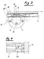
- the roller carrier 107 has only one pair of rollers 119 with two rollers 121.
- the shaft 123 of the pair of rollers 119 is held in a bore 124 in the roller carrier 107.
- the roller carrier 107 additionally has a recess 125, the diameter of which is dimensioned large enough to axially pass one of the rollers 121 through.
- a connecting slot 126 the width of which is slightly smaller than the diameter of the shaft 123, connects the recess 125 to the bore 124, which serves as a bearing for the shaft 123.
- a self-tapping fastening device 137 for holding the roller carrier 107 within a pot hole 133 in the door 101 can also be arranged.
- the fastening device 137 can be made from a pivotable bearing about an axis (A) in the roller carrier 107, there are boomerang-shaped knives, which in the swung-in state lies completely within the roller carrier 107 (solid lines) and whose ends 141, 142 in the swung-out state carry over the lateral surface of the roller carrier 107 (broken lines).
- the knife 137 has a pivot shaft 145 with a slot-shaped or a hexagonal engagement 147 for a tool, for example a screwdriver.
- the roller carrier 107 with the self-tapping knife 137 is inserted directly into the pot bore or recess 133 on the upper edge 3 of the sliding door 1 and locked in place with the door 1 by turning the engagement 147.
- a bore can be provided in the center of the roller carrier 107, through which a screw can be passed and screwed into the base of the pot bore 133 (not shown).
- the roller carrier 107 could also be inserted into a receiving sleeve, as shown in FIGS. 1 to 3.
- the fastening device 137 has a segment-shaped knife 237 which, in the swung-out state (shown in broken lines), projects like a sickle-like over the jacket of the roller carrier 207.
- the pivoting of the knife 207 takes place analogously and with the same means as are shown and described in FIGS. 5 and 6.
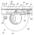
- the roller carrier 307 has a flange 351 in which a fastening screw 353 is embedded.
- the fastening screw 353 prevents the roller carrier 307 from rotating and also holds it in the corresponding cup bore in the sliding door 301.
- the roller carrier 307 in turn has only a single pair of rollers 321 which sits on the ends of a shaft 323.
- the two stops 355 are part of the roller carrier 307.
- the surface 359 of the stops facing upwards 355 is wave-shaped and designed to receive an elastic retaining finger 361.
- the retaining finger 361 is held clamped in the running rail 311 by means of a locking screw 363.
- a buffer surface 365 is also formed on the retaining finger 361, against which the stop surface 357 is intended to lie over a large area.
Landscapes
- Engineering & Computer Science (AREA)
- Mechanical Engineering (AREA)
- Support Devices For Sliding Doors (AREA)
- Lubrication Of Internal Combustion Engines (AREA)
- Surgical Instruments (AREA)
Claims (9)
- Mécanisme de déplacement à moyens de guidage pour une porte coulissante agencée de façon à pouvoir être montée dans un placard, dans lequel les moyens de guidage sont destinés à être situés à l'intérieur d'un rail profilé, disposé sur le panneau supérieur d'un placard, et qui comporte un support pour les moyens de guidage qui porte au moins un moyen de guidage, le support étant maintenu dans une douille réceptrice qui est mise en place dans un trou en cuvette ménagé sur la porte coulissante, caractérisé en ce qu'en tant que moyens de guidage, une paire de galets (19, 21) est montée sur un support (7, 307), lequel support (7, 307) est formé d'un corps de base (13, 113, 213, 313) pratiquement cylindrique et d'un corps de palier (17, 117, 217, 317) qui est fixé sur ce corps de base et sert au montage de la paire de galets (19, 119, 219, 319), le corps de base (13, 113, 213, 313) étant maintenu dans la douille réceptrice (5), encastrée dans la porte de placard (1), de façon à pouvoir pivoter autour de l'axe horizontal (A).
- Mécanisme de déplacement selon la revendication 1, caractérisé en ce que le porte-galets (7) porte deux paires de galets (19) disposées l'une à côté de l'autre.
- Mécanisme de déplacement selon la revendication 1, caractérisé en ce que le corps de palier (117) comporte un évidement (125) permettant l'introduction axiale de la paire de galets (119) montée sur un axe (123), cet évidement étant relié radialement par une fente à un perçage (124) qui est destiné à servir de palier à l'axe (123) qui porte les galets à ses extrémités.
- Mécanisme de déplacement selon l'une des revendications 2 et 3, caractérisé en ce qu'une nervure ou une gorge circonférentielle (15) est ménagée sur la surface périphérique du porte-galets (7) et une gorge correspondante ou une nervure correspondante (35) est ménagée dans l'alésage (33) situé dans la douille réceptrice (5).
- Mécanisme de déplacement selon la revendication 4, caractérisé en ce que la douille réceptrice (5) comporte une surface périphérique cylindrique et, se raccordant à cette dernière, une collerette (8) servant de surface d'appui/application sur la porte coulissante (1) et/ou pour la fixation sur cette porte coulissante (1);
- Mécanisme de déplacement selon l'une des revendications 1 à 5, caractérisé en ce qu'un protecteur antisalissures (27) est disposé sur le porte-galets (7, 107, 207) d'une façon permettant une action élastique.
- Mécanisme de déplacement selon l'une des revendications 1 et 3 à 6, caractérisé en ce que, sur le porte-galets (107, 207, 307) et sur les côtés vis-à-vis des galets (321), il est disposé des butées (355) comportant des surfaces de butée (357) qui sont destinées à venir en appui sur des surfaces correspondantes d'amortissement (365) situées aux extrémités des rails de guidage (111, 211, 311).
- Mécanisme de déplacement selon la revendication 7, caractérisé en ce que les butées (355) sont constituées par des ailes réalisées sur le porte-galets (307) et venant en appui parallèlement au rail de guidage (311) et en ce que les surfaces des ailes qui sont tournées vers le haut sont réalisées avec la forme d'une onde.
- Mécanisme de déplacement selon la revendication 8, caractérisée en ce que des moyens élastiques de retenue (361), destinés à s'enclencher d'une manière séparable sur les butées (355), sont montés dans les rails de guidage (311) de façon à pouvoir être réglés en position et immobilisés.
Applications Claiming Priority (4)
| Application Number | Priority Date | Filing Date | Title |
|---|---|---|---|
| CH733/92 | 1992-03-06 | ||
| CH73392 | 1992-03-06 | ||
| CH3201/92 | 1992-10-13 | ||
| CH320192 | 1992-10-13 |
Publications (2)
| Publication Number | Publication Date |
|---|---|
| EP0592357A1 EP0592357A1 (fr) | 1994-04-13 |
| EP0592357B1 true EP0592357B1 (fr) | 1995-02-15 |
Family
ID=25685527
Family Applications (1)
| Application Number | Title | Priority Date | Filing Date |
|---|---|---|---|
| EP93810108A Expired - Lifetime EP0592357B1 (fr) | 1992-03-06 | 1993-02-19 | Chariot à galet |
Country Status (5)
| Country | Link |
|---|---|
| US (1) | US5404675A (fr) |
| EP (1) | EP0592357B1 (fr) |
| AT (1) | ATE118588T1 (fr) |
| DE (1) | DE59300084D1 (fr) |
| ES (1) | ES2074922T3 (fr) |
Families Citing this family (30)
| Publication number | Priority date | Publication date | Assignee | Title |
|---|---|---|---|---|
| ES2066637B1 (es) * | 1992-03-11 | 1996-12-16 | Hernando M Del Rosario Garcia | Dispositivo de guiado y rodadura de cargas compensadas de puertas correderas. |
| FR2756587B1 (fr) * | 1996-12-03 | 1999-01-15 | Ferco Int Usine Ferrures | Dispositif de roulement pour ouvrant coulissant |
| PT920564E (pt) * | 1997-06-24 | 2003-03-31 | Hawa Ag | Dispositivo para ligar um elemento deslocavel a um dispositivo de guia |
| DE59915094D1 (de) * | 1998-08-21 | 2009-11-19 | Eku Ag | Laufwerks-Anordnung für eine Schiebetür |
| EP0984127B1 (fr) * | 1998-09-03 | 2009-05-06 | Eku Ag | Mécanisme de roulement pour porte coulissante |
| DE50012954D1 (de) * | 1999-06-10 | 2006-07-27 | Eku Ag | Laufwerk für eine Schiebetür |
| US6209171B1 (en) | 1999-10-01 | 2001-04-03 | The Stanley Works | Movable door mounting assembly |
| ES2277824T3 (es) * | 1999-12-13 | 2007-08-01 | Eku Ag | Conjunto de mecanismo de rodadura para una puerta de corredera. |
| US6520090B2 (en) | 2001-04-24 | 2003-02-18 | Stanley D. Hudson | Overhead rail system including a U-bracket and an end stop |
| DE102004062764A1 (de) | 2004-12-21 | 2006-06-29 | Geze Gmbh | Rollenwagen |
| US7730670B2 (en) * | 2005-03-01 | 2010-06-08 | Mr. Shower Door, Inc. | Sliding door assembly |
| US20060277850A1 (en) * | 2005-06-08 | 2006-12-14 | Gravel Donald P | Partition panel assembly |
| CN101365857B (zh) * | 2006-01-17 | 2012-05-23 | 日本文化钢卷帘门股份公司 | 带制动器装置的开闭装置 |
| DE102007059624A1 (de) * | 2007-12-10 | 2009-06-18 | Raumplus Gmbh & Co. Kg | Wand-, Tür- oder Fensterelement |
| IT1398112B1 (it) * | 2010-02-15 | 2013-02-07 | Eclisse Srl | Dispositivo di supporto ed ancoraggio in sospensione del pannello porta in un controtelaio per porte scorrevoli. |
| US8528283B2 (en) * | 2010-02-24 | 2013-09-10 | 3Form, Inc. | Pivoting wedge panel mounting assemblies and systems |
| US8327591B2 (en) * | 2010-03-24 | 2012-12-11 | Wilkinson Jr Edgar L | Overhead panel and installation system |
| US9833072B1 (en) * | 2010-11-23 | 2017-12-05 | Drawers In Motion, LLC | Rack and drawer systems and devices |
| US10376057B2 (en) | 2010-11-23 | 2019-08-13 | Drawers In Motion, LLC | Rack and drawer systems |
| US8905500B2 (en) * | 2011-05-13 | 2014-12-09 | Steelcase Inc. | Storage assembly includes a base assembly, a first cabinet assembly and a second cabinet assembly with each slidable with respect to the base assembly |
| DE102011056037B3 (de) * | 2011-12-05 | 2013-08-01 | Martin Staud GmbH & Co. KG | Schalter-Vorrichtung für einen Wandschrank und Wandschrank mit einer derartigen Vorrichtung |
| PL2740870T3 (pl) * | 2012-12-05 | 2022-01-03 | Hawa Sliding Solutions Ag | Urządzenie w postaci prowadnicy dla przesuwnych oraz obrotowych elementów oddzielających oraz jednostka funkcjonalna |
| US20140157545A1 (en) * | 2012-12-06 | 2014-06-12 | Enzo Maola | Rollo-flex assembly |
| DE102014101158B4 (de) | 2014-01-30 | 2026-03-26 | Lamello Ag | Verbindungsmittel und Verfahren zum Verbinden zweier Bauteile |
| CN104018751B (zh) * | 2014-06-13 | 2016-08-24 | 许姜德 | 吊趟门用上吊挂滑轮装置 |
| EP3606817B2 (fr) * | 2017-04-04 | 2023-12-13 | Safran Seats | Dispositif de fermeture d'un passage entre deux unités de sièges |
| CN107939202B (zh) * | 2017-10-27 | 2024-07-02 | 佛山市金砥柱建筑装饰材料有限公司 | 滑轮尾部安装结构 |
| US12134475B2 (en) * | 2019-10-29 | 2024-11-05 | Safran Seats GB Limited | Emergency passage door |
| DE102019217467A1 (de) * | 2019-11-12 | 2021-05-12 | Lamello Ag | Adapterelement und Verbindungsvorrichtung |
| WO2022219641A1 (fr) * | 2021-04-16 | 2022-10-20 | Kineco Limited | Ensemble excentrique pour porte coulissante |
Family Cites Families (21)
| Publication number | Priority date | Publication date | Assignee | Title |
|---|---|---|---|---|
| US699971A (en) * | 1902-01-31 | 1902-05-13 | Georg Poschmann | Curtain-pole. |
| US1610282A (en) * | 1925-06-10 | 1926-12-14 | A L Hansen Mfg Company | Sliding-door fixture |
| US2230615A (en) * | 1940-02-14 | 1941-02-04 | Otto D Dick | Door hanger |
| DE1259059B (de) * | 1961-11-07 | 1968-01-18 | Wilhelm Hachtel | Rollbarer Vorhangtraeger |
| US3155149A (en) * | 1962-01-30 | 1964-11-03 | Kirsch Co | Structural device |
| DE1259062B (de) * | 1964-06-05 | 1968-01-18 | Wilhelm Hachtel | Traeger zum Aufhaengen von Vorhaengen od. dgl. an Innenlaeufer-Vorhangschienen |
| CH442067A (de) * | 1965-04-23 | 1967-08-15 | Idealheim Ag | Schiebetüre |
| DE1269309B (de) * | 1965-07-30 | 1968-05-30 | Wilhelm Hachtel | Rollender Aufhaenger aus Kunststoff fuer Gardinen oder Vorhaenge |
| DE1259044B (de) * | 1966-05-18 | 1968-01-18 | Wilhelm Hachtel | Verschlussstueck fuer die Einfuehrungsoeffnung an Vorhangschienen |
| DE1259045B (de) * | 1966-05-18 | 1968-01-18 | Wilhelm Hachtel | Innenlaeufer-Vorhangschiene fuer rollende oder gleitende Vorhangtraeger |
| CH451742A (de) * | 1966-06-21 | 1968-05-15 | Ziegler Franz | Glas-Schiebetürbeschlag |
| DE1708300A1 (de) * | 1966-09-29 | 1971-05-19 | Franz Ziegler | Aufhaengebeschlag fuer Schiebetueren |
| US3457677A (en) * | 1967-10-09 | 1969-07-29 | Franz Ziegler | Door fitting for glass sliding suspension doors |
| AT300609B (de) * | 1968-12-13 | 1972-06-15 | Huwilwerke Hugo Willach & Sohn | Aufhaengebeschlag fuer schiebetueren |
| DE2110360C3 (de) * | 1971-03-04 | 1976-01-08 | Trola-Kunststofferzeugnisse Gmbh & Co, 8501 Schwaig | Beschlag, insbesondere zum lösbaren Aufhängen einer Schiebetür an eine Führungsschiene |
| DE2206447A1 (de) * | 1972-02-11 | 1973-08-16 | Hueppe Justin Fa | Laufschienen- und tragrollensystem fuer trennwandelemente |
| DE8433632U1 (de) * | 1984-11-16 | 1985-02-14 | Hespe & Woelm Gmbh & Co Kg, 5628 Heiligenhaus | Haengevorrichtung |
| US4872287A (en) * | 1988-05-13 | 1989-10-10 | C. Hager & Sons Hinge Manufacturing Company | Latching mechanism for trolley-hung doors |
| DE8913815U1 (de) * | 1989-11-23 | 1990-01-11 | Trola Kunststofferzeugnisse GmbH, 8501 Schwaig | Rolleneinsatz für Schiebetüren von Möbeln u.dgl. |
| US5189758A (en) * | 1990-09-26 | 1993-03-02 | Levy James F | Support system for a flexible closure |
| IT1243959B (it) * | 1990-11-30 | 1994-06-28 | Movi Srl | Complesso per la sospensione e lo scorrimento di pannelli scorrevoli |
-
1993
- 1993-02-19 EP EP93810108A patent/EP0592357B1/fr not_active Expired - Lifetime
- 1993-02-19 AT AT93810108T patent/ATE118588T1/de not_active IP Right Cessation
- 1993-02-19 ES ES93810108T patent/ES2074922T3/es not_active Expired - Lifetime
- 1993-02-19 DE DE59300084T patent/DE59300084D1/de not_active Expired - Lifetime
- 1993-03-05 US US08/026,600 patent/US5404675A/en not_active Expired - Lifetime
Also Published As
| Publication number | Publication date |
|---|---|
| EP0592357A1 (fr) | 1994-04-13 |
| DE59300084D1 (de) | 1995-03-23 |
| US5404675A (en) | 1995-04-11 |
| ES2074922T3 (es) | 1995-09-16 |
| ATE118588T1 (de) | 1995-03-15 |
Similar Documents
| Publication | Publication Date | Title |
|---|---|---|
| EP0592357B1 (fr) | Chariot à galet | |
| DE3200310A1 (de) | Gestell aus mehreren profilstaeben | |
| DE19947670B4 (de) | Drehband für Türen oder Fenster | |
| EP1020154A2 (fr) | Cloison de douche | |
| DE102014109429B4 (de) | Beschlag für eine Schiebetür | |
| DE19901644A1 (de) | Befestigungsplatte | |
| DE202006004198U1 (de) | Mehrachsenscharnier mit integrierter Höhenverstellhilfe für den bei geschlossener Tür nicht sichtbaren Einbau | |
| DE102009027242A1 (de) | Bewegliche Trennwand | |
| DE19858709A1 (de) | Scharnier, insbesondere für Türflügel von Duschabtrennungen | |
| EP0698710B1 (fr) | Penture pour portes, fenêtres et similaires | |
| DE3719516A1 (de) | Tuer- oder fensterband | |
| WO2025056287A1 (fr) | Ferrure de porte coulissante et agencement de porte coulissante associé | |
| EP1160406A2 (fr) | Charnière avec surface d'appui encochée | |
| EP1605125A2 (fr) | Système de guidage pour guider des portes coulissantes ou des fenêtres coulissantes | |
| EP0984126B1 (fr) | Dispositif de guidage pour une porte coulissante | |
| DE10301046B4 (de) | Drehbeschlag für die verdeckte Anordnung an Türen oder Fenstern | |
| EP2157266B1 (fr) | Charnière pour un article de mobilier doté d'une porte | |
| EP1460225B1 (fr) | Chariot pour une porte coulissante | |
| WO1996014489A1 (fr) | Penture de porte | |
| AT403826B (de) | Scharnier für fenster, türen od. dgl., insbesondere für dreh-kippbeschläge mit einer ausstellvorrichtung | |
| EP1757765B2 (fr) | Porte avec cadre étroit | |
| DE10323695A1 (de) | Schiebetürprofil | |
| EP1215356B1 (fr) | Ensemble de charnières pour portes, fenêtres et similaires | |
| DE29606911U1 (de) | Vorrichtung zum Zusammenbau von Ausrüstung | |
| DE29509177U1 (de) | Türband |
Legal Events
| Date | Code | Title | Description |
|---|---|---|---|
| PUAI | Public reference made under article 153(3) epc to a published international application that has entered the european phase |
Free format text: ORIGINAL CODE: 0009012 |
|
| 17P | Request for examination filed |
Effective date: 19930524 |
|
| AK | Designated contracting states |
Kind code of ref document: A1 Designated state(s): AT CH DE ES FR GB IT LI |
|
| GRAA | (expected) grant |
Free format text: ORIGINAL CODE: 0009210 |
|
| AK | Designated contracting states |
Kind code of ref document: B1 Designated state(s): AT CH DE ES FR GB IT LI |
|
| REF | Corresponds to: |
Ref document number: 118588 Country of ref document: AT Date of ref document: 19950315 Kind code of ref document: T |
|
| ET | Fr: translation filed | ||
| REF | Corresponds to: |
Ref document number: 59300084 Country of ref document: DE Date of ref document: 19950323 |
|
| ITF | It: translation for a ep patent filed | ||
| REG | Reference to a national code |
Ref country code: CH Ref legal event code: PFA Free format text: EKU AG |
|
| GBT | Gb: translation of ep patent filed (gb section 77(6)(a)/1977) |
Effective date: 19950517 |
|
| RAP2 | Party data changed (patent owner data changed or rights of a patent transferred) |
Owner name: EKU AG |
|
| REG | Reference to a national code |
Ref country code: ES Ref legal event code: FG2A Ref document number: 2074922 Country of ref document: ES Kind code of ref document: T3 |
|
| PLBE | No opposition filed within time limit |
Free format text: ORIGINAL CODE: 0009261 |
|
| STAA | Information on the status of an ep patent application or granted ep patent |
Free format text: STATUS: NO OPPOSITION FILED WITHIN TIME LIMIT |
|
| 26N | No opposition filed | ||
| REG | Reference to a national code |
Ref country code: GB Ref legal event code: IF02 |
|
| PGFP | Annual fee paid to national office [announced via postgrant information from national office to epo] |
Ref country code: GB Payment date: 20070103 Year of fee payment: 15 |
|
| PGFP | Annual fee paid to national office [announced via postgrant information from national office to epo] |
Ref country code: CH Payment date: 20070209 Year of fee payment: 15 |
|
| PGFP | Annual fee paid to national office [announced via postgrant information from national office to epo] |
Ref country code: ES Payment date: 20070222 Year of fee payment: 15 |
|
| PGFP | Annual fee paid to national office [announced via postgrant information from national office to epo] |
Ref country code: IT Payment date: 20070629 Year of fee payment: 15 |
|
| PGFP | Annual fee paid to national office [announced via postgrant information from national office to epo] |
Ref country code: FR Payment date: 20070112 Year of fee payment: 15 |
|
| PGFP | Annual fee paid to national office [announced via postgrant information from national office to epo] |
Ref country code: AT Payment date: 20080226 Year of fee payment: 16 |
|
| REG | Reference to a national code |
Ref country code: CH Ref legal event code: PL |
|
| GBPC | Gb: european patent ceased through non-payment of renewal fee |
Effective date: 20080219 |
|
| PG25 | Lapsed in a contracting state [announced via postgrant information from national office to epo] |
Ref country code: LI Free format text: LAPSE BECAUSE OF NON-PAYMENT OF DUE FEES Effective date: 20080229 Ref country code: CH Free format text: LAPSE BECAUSE OF NON-PAYMENT OF DUE FEES Effective date: 20080229 |
|
| REG | Reference to a national code |
Ref country code: FR Ref legal event code: ST Effective date: 20081031 |
|
| PG25 | Lapsed in a contracting state [announced via postgrant information from national office to epo] |
Ref country code: FR Free format text: LAPSE BECAUSE OF NON-PAYMENT OF DUE FEES Effective date: 20080229 |
|
| REG | Reference to a national code |
Ref country code: ES Ref legal event code: FD2A Effective date: 20080220 |
|
| PG25 | Lapsed in a contracting state [announced via postgrant information from national office to epo] |
Ref country code: GB Free format text: LAPSE BECAUSE OF NON-PAYMENT OF DUE FEES Effective date: 20080219 |
|
| PG25 | Lapsed in a contracting state [announced via postgrant information from national office to epo] |
Ref country code: ES Free format text: LAPSE BECAUSE OF NON-PAYMENT OF DUE FEES Effective date: 20080220 |
|
| PG25 | Lapsed in a contracting state [announced via postgrant information from national office to epo] |
Ref country code: IT Free format text: LAPSE BECAUSE OF NON-PAYMENT OF DUE FEES Effective date: 20080219 |
|
| PG25 | Lapsed in a contracting state [announced via postgrant information from national office to epo] |
Ref country code: AT Free format text: LAPSE BECAUSE OF NON-PAYMENT OF DUE FEES Effective date: 20090219 |
|
| PGFP | Annual fee paid to national office [announced via postgrant information from national office to epo] |
Ref country code: DE Payment date: 20110203 Year of fee payment: 19 |
|
| REG | Reference to a national code |
Ref country code: DE Ref legal event code: R119 Ref document number: 59300084 Country of ref document: DE Effective date: 20120901 |
|
| PG25 | Lapsed in a contracting state [announced via postgrant information from national office to epo] |
Ref country code: DE Free format text: LAPSE BECAUSE OF NON-PAYMENT OF DUE FEES Effective date: 20120901 |