EP0592452B1 - Strassenmarkierungsverfahren, Aufbringen von Markierungselementen - Google Patents
Strassenmarkierungsverfahren, Aufbringen von Markierungselementen Download PDFInfo
- Publication number
- EP0592452B1 EP0592452B1 EP92907462A EP92907462A EP0592452B1 EP 0592452 B1 EP0592452 B1 EP 0592452B1 EP 92907462 A EP92907462 A EP 92907462A EP 92907462 A EP92907462 A EP 92907462A EP 0592452 B1 EP0592452 B1 EP 0592452B1
- Authority
- EP
- European Patent Office
- Prior art keywords
- rib
- pads
- road surface
- pad
- line
- Prior art date
- Legal status (The legal status is an assumption and is not a legal conclusion. Google has not performed a legal analysis and makes no representation as to the accuracy of the status listed.)
- Expired - Lifetime
Links
Images


Classifications
-
- E—FIXED CONSTRUCTIONS
- E01—CONSTRUCTION OF ROADS, RAILWAYS, OR BRIDGES
- E01C—CONSTRUCTION OF, OR SURFACES FOR, ROADS, SPORTS GROUNDS, OR THE LIKE; MACHINES OR AUXILIARY TOOLS FOR CONSTRUCTION OR REPAIR
- E01C23/00—Auxiliary devices or arrangements for constructing, repairing, reconditioning, or taking-up road or like surfaces
- E01C23/16—Devices for marking-out, applying, or forming traffic or like markings on finished paving; Protecting fresh markings
- E01C23/18—Devices for marking-out, applying, or forming traffic or like markings on finished paving; Protecting fresh markings for applying prefabricated markings
-
- E—FIXED CONSTRUCTIONS
- E01—CONSTRUCTION OF ROADS, RAILWAYS, OR BRIDGES
- E01F—ADDITIONAL WORK, SUCH AS EQUIPPING ROADS OR THE CONSTRUCTION OF PLATFORMS, HELICOPTER LANDING STAGES, SIGNS, SNOW FENCES, OR THE LIKE
- E01F9/00—Arrangement of road signs or traffic signals; Arrangements for enforcing caution
- E01F9/50—Road surface markings; Kerbs or road edgings, specially adapted for alerting road users
- E01F9/553—Low discrete bodies, e.g. marking blocks, studs or flexible vehicle-striking members
Definitions
- This invention relates to a method of applying road markings to motorways, trunk roads and the like. Specifically the invention is concerned with the application of rib pads to a road surface, such that the rib pads protrude above the road surface and are applied at spaced intervals along a road. The application of the said pads is performed by mechanical means such that the application can be accurately performed.
- rib pads protrude above the road surface and as such, in general terms, shall be evident above road surface water.
- rib pads are applied to the road surface by means of a complicated and expensive vehicle which is required to lay down fluent and molten material to form a base strip on the surface as the vehicle travels along the surface with the rib pad itself being formed of a similar material to that of the base strip.
- the strip pads are formed by a mechanical shutter mechanism which allows a blob of material to form on the strip.
- the equipment for the application of the rib comprises a hopper for the material and a heating means.
- the molten material is applied to the road surface in the form of a base strip and a series of blobs.
- the machinery so described has the disadvantage of requiring the rib application to be performed at the same time as the base strip is laid. This has the effect of slowing down the application process when the time allowed for the process is frequently limited by traffic flow constraints i.e in the form of limitation of traffic congestion. Furthermore, if failure occurs in the operation of any part of the application machine, then it is difficult to continue the road marking operation until a replacement machine is available.
- EPA 0397406 discloses the application of rib pads to a pre-applied line by heating the same with a blow torch or to have the line in a molten condition having just been applied. This patent however teaches that the rib pads must be kept in a rigid condition to allow the same to be bonded to a line of paint in a molten condition.
- the present invention aims to provide the application of rib pads to a surface to form a rumble strip or demarcation strip wherein the pads are applied to a base strip when in a molten state or with at least a molten layer so that said pad molten layer can take into account any irregularities in the surface to which the same is to be applied and to perform said application by automated apparatus comprising placing and securing operations for the application of each rib pad.
- automated apparatus comprising placing and securing operations for the application of each rib pad.
- apparatus for making a rumble strip or demarcation line of a type having a plurality of protrusions at spaced intervals on a road surface comprising a movable rib pad laying unit for moving at predeterminable speeds along the road surface; integrated rib pad laying equipment for laying the preformed rib pads, said integrated rib pad laying equipment including a magazine for holding a plurality of said preformed rib pads; means for removing at selected time intervals a pad from the magazine; means for placing said preformed rib pads onto the road surface and characterised in that dedicated heating means are provided and directed to heat the rib pads so that when the rib pads are in position on the line of paint or road surface the underside thereof have a layer of softened material formed from the material of the rib pad to bond with the road surface or pre-applied line of paint.
- the apparatus allows for the automated heating and laying of said rib pads.
- a means for forming a rumble strip on a road surface wherein said rumble strip comprises a base line of paint of thermoplastic and a series of raised protrusions, each of said protrusions being provided by the application of a rib pad to the base line.
- the base line will be previously applied and can be heated to a molten state prior to the rib pads being applied thereto.
- the rib pads are secured by pressing the rib pad into the molten surface by a further operation.
- the operation so described will be performed from one rib pad laying unit.
- the said rib pads can be stored on the rib pad laying road unit by means of a magazine mounted thereon such that the rib pad to be laid is removed from the bottom thereof.
- the pads can be preformed on the rib pad laying road unit from, in one embodiment, a roll mounted on the said rib pad laying road unit wherein the rib pads to be laid are punched out therefrom prior to being laid by the placing mechanism.
- the operations of heating, placing and securing of the rib pads so described can be performed by the rib pad laying road unit in sequence such that the direction and speed of movement of the unit shall be continuous.
- the rib pad laying road unit is capable of applying the rib pads at regular spaced intervals and said spaced intervals are adjustable to suit the required spacing intervals.
- the rib pad laying road unit is capable of applying pads of varying dimensions to the required surface.
- the apparatus for the application of the pads can heat the surface to which the rib pads are to be applied, by applying heat produced from gas burners mounted in close proximity to the said surface, to a state of fluidity sufficient to accept therein the rib pads.
- the rib pad securing operation of the pad laying unit can be performed by either a wheel which, upon passing over the pad, serves to press the pad into position.
- the wheel is replaced by a heating head which heats the pad sufficiently so that it will, in effect, form as one with the molten base surface.
- a method of forming a rumble strip or demarcation line on a road surface or pre-applied line of paint comprising the steps of moving a rib pad laying unit along the surface of the road ; depositing a plurality of rib pads along said surface of the road or pre-applied line of paint; controlling the distance between sequentially deposited rib pads and characterised by applying heat to said deposited rib pads to form a bonding layer of softened material of the rib pad so that the said bonding layer bonds with the road surface or pre-applied line of paint.
- the rib pads can be laid by the means of a manually controlled rib pad laying unit wherein the said unit is manually controlled by an operator and the laying operations are controlled by means of mechanical actuation, as the said unit is moved along the surface.
- said rib pads are applied immediately after the said base strip laying operation.
- Said molten base strip can be applied from the rib pad laying road unit.
- the rib pads are applied to a road surface to form a demarcation line wherein said rib pad is applied to a blob of material such as molten plastic in a molten state applied to the road surface prior to the application of the rib pads.
- said rib pads are applied to the blobs of material and said rib pads and blobs of material are oversprayed or painted with a substantially continuous line of material to form a rumble strip.
- said rib pads after application, can be oversprayed with paint to form a rumble strip.
- said rib pads are manufactured from plastics material remote from the laying of the rib pads.
- the rib pad is formed of thermoplastics material with a reflective top surface provided by light reflective spheres embedded in the plastics.
- the capability to apply reflective beads to the rib pads such that the reflective quality of the rib pads is enhanced.
- the said beads are applied to the rib pads by the means of a spray of the said beads.
- the pads may be further reflectorised by the attachment of reflective devices to the rib pads and preferably along the longitudinal edges of same.
- said rib pads will have reflective strips attached to the vertical edges of said strips.
- Thermoplastic material of varied colours may be used in the manufacture of the said rib pads to suit the statutory road marking colours required and the rib pad dimensions will be such that they can be laid on the base strip by the rib pad laying apparatus so described.
- the rib pads manufactured are of 4.5cm width and either 20cm, 15cm or 10cm in length.
- the rib pads can be manufactured by the extrusion of lengths of thermoplastic material, the said lengths being subsequently cut to form the said rib pads of required dimension.
- thermoplastic material it will be possible to control the flow of the extrusion of the thermoplastic material such that the material can be extruded in controlled lengths.
- This embodiment will provide means whereby a shutter mechanism will control the length of the rib pad to be produced by controlling the length of each extruded part to match.
- the extruded material shall be laid in a molten state onto polypropylene film to protect the conveying system from damage, and the extruded material shall be cooled as quickly as possible from the molten form by means of a blast freezer or by the treating of said material with water.
- the method of using rib pads with a soft bonding layer on the underside of the rib pads compensates for irregularities in the road surface to which rib pads are to be applied.
- the bonding on the underside of the rib pads shall be provided by the application of extra bonding to the underside of said rib pads.
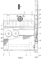
- the unit 2 is a four wheel vehicle having four wheels 4 and comprising a driver seating area 6, a fuel tank 8, gas canisters storage area 10, a tool box 12, work table 14, work platform 16 and a rib pad storage area 18.
- a driver seating area 6 a fuel tank 8
- gas canisters storage area 10 a tool box 12
- work table 14 work platform 16
- rib pad storage area 18 On one 22 of the edges 20 and 22 running longitudinally of the road unit 2 there is mounted the rib pad laying equipment 24.
- the rib pad laying equipment 24 comprises a burner section 26 which consists of a series of gas burners 28.
- a depositing assembly 32 is mounted behind the burner section 26 in relation to the direction of travel 30 of the road unit 2 and is followed by a presser roller 34 for applied rib pads.
- the rear of the road unit 2 is equipped with flasher lights 36 and has the capability of having hazard signs 38 fitted thereon.
- the depositing assembly 32 is shown in greater detail in Figures 3 and 4 and comprises a central column 42 in which the rib pads 40 are contained.
- Column 42 formed of two U-sectioned bars 44 and 46.
- spacers 48 (as shown in Fig 4) can be placed inside the column along with the said pads when loading the central column 42.
- a slot 52 therein allows one rib pad 40 at a time to be pushed by a mechanism 54 in the direction 56 onto a spring flap 58 held normally in a horizontal position by spring 60.
- the unit 2 In the order to lay the rib pads 40 the unit 2 is driven at a speed, approximately 1 mile (1.6 km) per hour, and on a path such that the rib pad laying equipment 24 is positioned above that line on road on which the rib pads 40 are to be laid.
- the burner section 26 supplied by gas from tanks 10 serves to melt the road surface immediately below the burners so that the surface melts which allows the rib pad 40 subsequently to be pressed therein.
- the rib pads are deposited by depositing assembly 32 Each rib pad is deposited by means of the pad having been pushed by mechanism 54 to reach a position 62 on the spring flap 58 and the holding force of the spring 60 is overcome by the returning action of the mechanism 54 which is connected to the said flap.This causes the flap to lower into the position shown by the broken lines 64 and allows the rib pad 40 to slide into position on the molten surface.
- the frequency of depositing the rib pads 40 on the surface is dependant on the frequency of reciprocation of the mechanism 54.
- the reciprocatory movement is controlled by a linkage geared to the engine of the road unit 2.
- the spacing of the rib pads 40 along the road is dependent upon the speed of the unit 2 and the frequency of reciprocation of the mechanism 54.
- each rib pad 40 When in postion on the surface, each rib pad 40 is pressed into the soft, heated road surface by the pad roller 34. Roller 34 passes over the said pad as the road unit 2 continues in direction 30.
- a pressing spider wheel may be used comprising radial arms each with a pressing bar on its extremity. The spider wheel rotates in synchronism with the laying of the pads so that each presser bar in turn comes down onto and presses a previously applied pad.
- the pad laying process of heating, placing and pressing is repeatedly and continuously performed as the said road unit continues in the direction 30, with the depositing assembly 32 being refilled with rib pads 40 when required by an operative on the road unit 2.
- the burners 28, column 32 and the presser being on a dedicated machine it may be connected to a conventional vehicle such as a lorry.
- the depositing assembly 32 consists of the mechanism 54 and the central column 42 as described previously.
- the spring flap 58 and spring 60 are omitted.
- the rib pads 40 are held in the central column 42 which as before has a slot 52 formed therein.
- the central column 32 is mounted at such an angle that the rib pads 40 are held in position so that the bottom rib pad 40 will not leave the central column 42 until pushed by mechanism 54 and when it is so pushed, it falls freely and predictably to the ground.
- the rib pad roller 34 may be removed and replaced by a heater head.
- the rib pad 40 once the rib pad 40 has been placed in position by the depositing assembly 32, it is heated by the heater head such that the rib pad melts sufficiently to allow a bond to be formed with the heated surface upon which it is laid. This prevents the pad from cracking due to the pad roller 34 passing over and especially when applied to uneven surfaces.
- the pads may be fed to a feed wheel having peripheral notches into which the pads are placed one by one, and as the process proceeds the wheel is rotated and carries the pads round the wheel one by one and presents them to the road surface. This can be used in any embodiment.
- the rib pad laying unit will be provided with means whereby a base strip can be laid onto the road surface prior to the rib pad application process. Typically this will involve the removal of the burner section 26 and replacement with a base line point application means.
- Figure 6 illustrates a rib pad laying unit wherein the burner section 26 and the roller 34 have been removed.
- the roller 34 has been replaced by a bead spraying mechanism 66 thereby illustrating the adaptability of the rib pad laying unit.
- the pads can be further reflectorised by reflective devices such as for example reflective tape or plastic reflectors, being placed, stuck or embedded into the longitudinal edges of the pads.
- the said reflective devices may be protected by a layer of hard wearing plastic film.
- Coloured thermoplastic material may be used for or with the pad,
- the pad may be formed wholly of the coloured thermoplastic material or may have a strip of the said material bonded thereto.
- the coloured edges can thus be placed facing towards the motorist for maximum reflectivity and warning.
- the three operations of heating, placing and securing may be performed by the means of a manually controlled and propelled rib pad laying road unit. Integral to this unit in one embodiment will be a means for heating the base strip and a manually controlled lever application mechanism whereby the rib pad can be laid on the road surface as the road unit is propelled along the road surface. The effect of the said three operations are similar to that provided by the powered road unit.
- the manually controlled road unit may be especially suited to operations which require increased manoeuvrability or involve only small stretches of rib pad laying.
- the mechanism for dispensing the pads can be attached to existing screed, spray and extruding machinery so that pads can be laid directly on to newly applied base lines whilst the material is still molten, thus alleviating the need for heating up of the base line.
- This unit has the advantage of providing, in one integral unit, a method of laying the said rib pads wherein the operations of heating, laying and pressing are part of one linked system with a comparatively high degree of automation which ensures that the rib pads 40 are laid in a systematic and efficient manner without the requirement for a simultaneously laid base strip.
- the rib pad laying road unit allows rib pads 40 of varying sizes to be laid independently of the laying of any base strip as is required by existing methods. This will allow the said rib pad laying to be performed more quickly and traffic congestion will be minimised and thus greater flexibility in the planning of a rib pad laying process is provided.
- this rib pad laying unit allows the operatives to operate from the vehicle itself which is equipped with hazard signs and affords the said operators a degree of protection against collision with any other vehicle.
- the ability to lay the rib pads to the road surface and then overspray allows the rib pads to be located as an integral part of a rumble strip whilst maintaining the flexibility of the rib pad laying mechanism.
- the ability to provide preformed, reflectorised rib pads, manufactured remote from the point of application to the road surface or base line provides a pad which is adaptable and flexible in use to form a demarcation line or rumble strip.
- the apparatus and method according to the invention in its various embodiments can be used for the creation of rumble strips in various circumstances as follows.
- the pads may be applied by heating and softening the road surface as described followed by application of the pads to the heated surface.
- the pads will mainly be of the rigid type described, but could be portions of molten material which subsequently hardens.
- the pads may stick to the road surface with adhesive, such as pressure sensitive adhesive on the underside of the pads.
- a strip of molten white lining material may be applied over the pads so that a rumble strip continuous white line is formed.
- the road surface along the line where the rumble strip has to be formed already has a white line
- this may be softened by heat and the pads applied to the softened material before it re-hardens.
- the pads may be rigid components or may be applied as molten portions.
- Another possibility is that the pads (rigid) can be stuck to the white line using adhesive.
- this may be applied as described herein by applying the molten material to the road surface to form the strip, followed by the application of the pads (rigid) whilst the strip is still warm and soft.
Landscapes
- Engineering & Computer Science (AREA)
- Architecture (AREA)
- Civil Engineering (AREA)
- Structural Engineering (AREA)
- Road Signs Or Road Markings (AREA)
- Road Repair (AREA)
Claims (7)
- Vorrichtung zur Herstellung eines/einer Markierungsstreifens oder -linie der Art mit einer Mehrzahl von beabstandeten Vorsprüngen auf einer Straßenoberfläche, umfassend eine bewegliche Markierungselemente-Verlegeeinheit (2), die mit einer einstellbaren Geschwindigkeit über die Straßenoberfläche bewegt werden kann, ein integriertes Markierungselemente-Verlegegerät (24) zum Verlegen der vorgeformten Markierungselemente (40), wobei das genannte integrierte Markierungselemente-Verlegegerät (24) ein Magazin (42) zur Aufnahme einer Mehrzahl der genannten vorgeformten Markierungselemente (40) aufweist, ein Mittel (32) zur Entnahme eines Elementes (40) in gewählten Zeitabständen (40) aus dem Magazin (42), Mittel (54, 58, 60) zum Verlegen der genannten vorgeformten Markierungselemente (40) auf die Straßenoberfläche, dadurch gekennzeichnet, daß spezielle Heizmittel vorgesehen sind, die so gerichtet werden, daß sie die Markierungselemente erhitzen, so daß sich auf der Unterseite der Markierungselemente, wenn sie in ihrer Position auf der Farblinie oder Straßenoberfläche liegen, eine Schicht aus erweichtem Material bildet, die aus dem Material der Platte besteht und mit der Straßenoberfläche oder der zuvor aufgebrachten Farblinie verklebt.
- Vorrichtung nach Anspruch 1, dadurch gekennzeichnet, daß das Heizmittel (26) vorgesehen ist, um die Straßenoberfläche oder die zuvor aufgebrachte Farblinie vor dem Aufbringen des Markierungselementes darauf zu erhitzen.
- Vorrichtung nach Anspruch 1, dadurch gekennzeichnet, daß ferner ein Basisstreifenauftragsmittel zum Aufbringen eines Basisstreifens auf die Straßenoberfläche vor dem Aufbringen der Markierungselemente (40) darauf vorgesehen ist.
- Verfahren zur Herstellung eines/einer Markierungsstreifens oder -linie auf einer Straßenoberfläche oder einer zuvor aufgebrachten Farblinie, wobei das Verfahren die folgenden Schritte umfaßt: Bewegen einer Markierungselemente-Verlegeeinheit (2) über die Oberfläche der Straße, Aufbringen einer Mehrzahl von Markierungselementen (40) entlang der genannten Oberfläche der Straße oder der zuvor aufgebrachten Farblinie; Regeln des Abstands zwischen nacheinander aufgebrachten Markierungselementen (40), dadurch gekennzeichnet, daß die Unterseite der genannten Markierungselemente (40) mit Wärme beaufschlagt wird, um eine Bondschicht aus erweichtem Material des Markierungselementes zu bilden, so daß die genannte Bondschicht mit der Straßenoberfläche oder der zuvor aufgebrachten Farblinie verklebt.
- Verfahren nach Anspruch 4, dadurch gekennzeichnet, daß die Bondschicht aus erweichtem Material auf der Unterseite der Markierungselemente gebildet wird, die mit der Straßenoberfläche oder der zuvor aufgebrachten Farblinie Kontakt erhalten.
- Verfahren nach Anspruch 5, dadurch gekennzeichnet, daß vor der Durchführung des genannten Schrittes des Aufbringens der Markierungselemente der weitere Schritt des Ladens einer Mehrzahl von vorgefertigten Platten (40) in ein Magazin (42) in der genannten Markierungselemente-Verlegeeinheit vorgesehen ist.
- Verfahren nach Anspruch 4, dadurch gekennzeichnet, daß die Straßenoberfläche oder die zuvor aufgebrachte Farblinie durch ein Heizmittel (26) vor dem Aufbringen der Markierungselemente darauf erhitzt wird.
Applications Claiming Priority (7)
| Application Number | Priority Date | Filing Date | Title |
|---|---|---|---|
| GB919107186A GB9107186D0 (en) | 1991-04-05 | 1991-04-05 | Rib pad manufacturing plant |
| GB919107185A GB9107185D0 (en) | 1991-04-05 | 1991-04-05 | Road marking method |
| GB9107186 | 1991-04-05 | ||
| GB9107185 | 1991-04-05 | ||
| GB9118719 | 1991-08-31 | ||
| GB919118719A GB9118719D0 (en) | 1991-08-31 | 1991-08-31 | Improvements in the application of rib pads for road marking |
| PCT/GB1992/000610 WO1992017648A1 (en) | 1991-04-05 | 1992-04-06 | Road marking method - the application of rib pads |
Publications (2)
| Publication Number | Publication Date |
|---|---|
| EP0592452A1 EP0592452A1 (de) | 1994-04-20 |
| EP0592452B1 true EP0592452B1 (de) | 1999-06-23 |
Family
ID=27265583
Family Applications (1)
| Application Number | Title | Priority Date | Filing Date |
|---|---|---|---|
| EP92907462A Expired - Lifetime EP0592452B1 (de) | 1991-04-05 | 1992-04-06 | Strassenmarkierungsverfahren, Aufbringen von Markierungselementen |
Country Status (7)
| Country | Link |
|---|---|
| EP (1) | EP0592452B1 (de) |
| AT (1) | ATE181580T1 (de) |
| AU (1) | AU673136B2 (de) |
| CA (1) | CA2107774A1 (de) |
| DE (1) | DE69229475T2 (de) |
| ES (1) | ES2136619T3 (de) |
| WO (1) | WO1992017648A1 (de) |
Family Cites Families (10)
| Publication number | Priority date | Publication date | Assignee | Title |
|---|---|---|---|---|
| GB1201548A (en) * | 1968-07-18 | 1970-08-05 | Prismo Safety Corp | Reflective markers and reflective elements therefor |
| DE1923877A1 (de) * | 1969-05-09 | 1970-11-19 | E Stieglan Fa | Fahrbare Strassenmarkierungsmaschine |
| GB1531480A (en) * | 1974-12-20 | 1978-11-08 | Bagshaw R | Retroreflective elements |
| US4136991A (en) * | 1977-06-02 | 1979-01-30 | Elin R. Clark | Roadway marker and process of and application for producing the same |
| US4607978A (en) * | 1982-08-23 | 1986-08-26 | Ludwig Eigenmann | Method and equipment for improving horizontal marking strips |
| BR8401650A (pt) * | 1983-04-11 | 1984-11-20 | Minnesota Mining & Mfg | Marcador elastomerico de pavimentacao |
| EP0279205B1 (de) * | 1984-04-10 | 1991-09-18 | Minnesota Mining And Manufacturing Company | Elastomere Fahrbahnmarkierung |
| US4888896A (en) * | 1987-06-29 | 1989-12-26 | Sanchez Richard E | Utility cut patch identification tag |
| GB8910454D0 (en) * | 1989-05-06 | 1989-06-21 | Mone Bros Roadmarkings Limited | Road marking method |
| US4974990A (en) * | 1989-10-24 | 1990-12-04 | Minnesota Mining And Manufacturing Company | Raised pavement marker applicator |
-
1992
- 1992-04-06 CA CA002107774A patent/CA2107774A1/en not_active Abandoned
- 1992-04-06 EP EP92907462A patent/EP0592452B1/de not_active Expired - Lifetime
- 1992-04-06 ES ES92907462T patent/ES2136619T3/es not_active Expired - Lifetime
- 1992-04-06 AT AT92907462T patent/ATE181580T1/de active
- 1992-04-06 AU AU15317/92A patent/AU673136B2/en not_active Ceased
- 1992-04-06 DE DE69229475T patent/DE69229475T2/de not_active Expired - Fee Related
- 1992-04-06 WO PCT/GB1992/000610 patent/WO1992017648A1/en not_active Ceased
Also Published As
| Publication number | Publication date |
|---|---|
| ES2136619T3 (es) | 1999-12-01 |
| WO1992017648A1 (en) | 1992-10-15 |
| CA2107774A1 (en) | 1992-10-06 |
| DE69229475D1 (de) | 1999-07-29 |
| ATE181580T1 (de) | 1999-07-15 |
| DE69229475T2 (de) | 2000-05-04 |
| AU1531792A (en) | 1992-11-02 |
| EP0592452A1 (de) | 1994-04-20 |
| AU673136B2 (en) | 1996-10-31 |
Similar Documents
| Publication | Publication Date | Title |
|---|---|---|
| EP0679208B1 (de) | Verfahren und vorrichtungzum auftragen eines in der nacht sichtbaren strassenmarkierungsstreifen | |
| US6505995B2 (en) | Road-marking machine | |
| CA1209391A (en) | Method and apparatus for applying roadway retro- reflecting elements | |
| EP0045180B1 (de) | Gerät zum Aufbringen von Strassenmarkierungsmaterial auf Strassen | |
| KR101454634B1 (ko) | 복합 융착식 차선도색장치 | |
| US20130230354A1 (en) | Multi-application apparatus, methods and surface markings | |
| WO2000047823A1 (en) | Audible night-visible traffic stripe for a road and method and apparatus for making the same | |
| AU673136B2 (en) | Road marking method - the application of rib pads | |
| KR101747370B1 (ko) | 융착식 차선 도색장치 | |
| US6217254B1 (en) | Marking on roads with a fixed road surface, such as asphalt, concrete or the like for motor vehicles and method for producing road markings | |
| EP0397406A1 (de) | Verfahren zum Markieren von Strassendecken | |
| US20240159001A1 (en) | Thermo truck with laterally disposed direct fired heating kettles and surface applicator system | |
| GB2329410A (en) | Hand-driven embossing device for road markings | |
| JPH11247132A (ja) | プロファイリングローラ及びプロファイル付与方法 | |
| KR102375743B1 (ko) | 노면표시 노후 페인트 처리기 | |
| JP2541874B2 (ja) | 道路の舗設方法とその装置 | |
| JP3824178B2 (ja) | 路面標示施工装置 | |
| EP1136623B1 (de) | Strassenmarkierungsvorrichtung | |
| JP3824179B2 (ja) | 路面標示施工装置及び路面標示施工方法 | |
| US6902348B2 (en) | Collated road marker assembly, and system and method for automatically applying collated road markers to roadway surfaces | |
| KR20030078206A (ko) | 노면표시 및 미끄럼방지면 포장의 시공장치, 그리고 이장치를 사용한 노면표시 및 미끄럼방지면 포장의 시공방법 | |
| FI109551B (fi) | Menetelmä ja laitteisto struktuurimerkinnän tekemiseksi ja struktuurimerkintä | |
| JP2541874C (de) |
Legal Events
| Date | Code | Title | Description |
|---|---|---|---|
| PUAI | Public reference made under article 153(3) epc to a published international application that has entered the european phase |
Free format text: ORIGINAL CODE: 0009012 |
|
| 17P | Request for examination filed |
Effective date: 19931104 |
|
| AK | Designated contracting states |
Kind code of ref document: A1 Designated state(s): AT BE CH DE DK ES FR GB GR IT LI LU MC NL SE |
|
| 17Q | First examination report despatched |
Effective date: 19950925 |
|
| GRAG | Despatch of communication of intention to grant |
Free format text: ORIGINAL CODE: EPIDOS AGRA |
|
| GRAG | Despatch of communication of intention to grant |
Free format text: ORIGINAL CODE: EPIDOS AGRA |
|
| GRAH | Despatch of communication of intention to grant a patent |
Free format text: ORIGINAL CODE: EPIDOS IGRA |
|
| GRAH | Despatch of communication of intention to grant a patent |
Free format text: ORIGINAL CODE: EPIDOS IGRA |
|
| GRAA | (expected) grant |
Free format text: ORIGINAL CODE: 0009210 |
|
| AK | Designated contracting states |
Kind code of ref document: B1 Designated state(s): AT BE CH DE DK ES FR GB GR IT LI LU MC NL SE |
|
| PG25 | Lapsed in a contracting state [announced via postgrant information from national office to epo] |
Ref country code: SE Free format text: THE PATENT HAS BEEN ANNULLED BY A DECISION OF A NATIONAL AUTHORITY Effective date: 19990623 Ref country code: NL Free format text: LAPSE BECAUSE OF FAILURE TO SUBMIT A TRANSLATION OF THE DESCRIPTION OR TO PAY THE FEE WITHIN THE PRESCRIBED TIME-LIMIT Effective date: 19990623 Ref country code: LI Free format text: LAPSE BECAUSE OF FAILURE TO SUBMIT A TRANSLATION OF THE DESCRIPTION OR TO PAY THE FEE WITHIN THE PRESCRIBED TIME-LIMIT Effective date: 19990623 Ref country code: GR Free format text: LAPSE BECAUSE OF NON-PAYMENT OF DUE FEES Effective date: 19990623 Ref country code: CH Free format text: LAPSE BECAUSE OF FAILURE TO SUBMIT A TRANSLATION OF THE DESCRIPTION OR TO PAY THE FEE WITHIN THE PRESCRIBED TIME-LIMIT Effective date: 19990623 Ref country code: BE Free format text: LAPSE BECAUSE OF FAILURE TO SUBMIT A TRANSLATION OF THE DESCRIPTION OR TO PAY THE FEE WITHIN THE PRESCRIBED TIME-LIMIT Effective date: 19990623 Ref country code: AT Free format text: LAPSE BECAUSE OF FAILURE TO SUBMIT A TRANSLATION OF THE DESCRIPTION OR TO PAY THE FEE WITHIN THE PRESCRIBED TIME-LIMIT Effective date: 19990623 |
|
| REF | Corresponds to: |
Ref document number: 181580 Country of ref document: AT Date of ref document: 19990715 Kind code of ref document: T |
|
| REG | Reference to a national code |
Ref country code: CH Ref legal event code: EP |
|
| REF | Corresponds to: |
Ref document number: 69229475 Country of ref document: DE Date of ref document: 19990729 |
|
| ITF | It: translation for a ep patent filed | ||
| PG25 | Lapsed in a contracting state [announced via postgrant information from national office to epo] |
Ref country code: DK Free format text: LAPSE BECAUSE OF FAILURE TO SUBMIT A TRANSLATION OF THE DESCRIPTION OR TO PAY THE FEE WITHIN THE PRESCRIBED TIME-LIMIT Effective date: 19990923 |
|
| ITF | It: translation for a ep patent filed | ||
| ET | Fr: translation filed | ||
| NLV1 | Nl: lapsed or annulled due to failure to fulfill the requirements of art. 29p and 29m of the patents act | ||
| REG | Reference to a national code |
Ref country code: ES Ref legal event code: FG2A Ref document number: 2136619 Country of ref document: ES Kind code of ref document: T3 |
|
| REG | Reference to a national code |
Ref country code: CH Ref legal event code: PL |
|
| PG25 | Lapsed in a contracting state [announced via postgrant information from national office to epo] |
Ref country code: LU Free format text: LAPSE BECAUSE OF NON-PAYMENT OF DUE FEES Effective date: 20000406 |
|
| PLBE | No opposition filed within time limit |
Free format text: ORIGINAL CODE: 0009261 |
|
| 26N | No opposition filed | ||
| PG25 | Lapsed in a contracting state [announced via postgrant information from national office to epo] |
Ref country code: MC Free format text: LAPSE BECAUSE OF NON-PAYMENT OF DUE FEES Effective date: 20001031 |
|
| PGFP | Annual fee paid to national office [announced via postgrant information from national office to epo] |
Ref country code: GB Payment date: 20010501 Year of fee payment: 10 |
|
| PGFP | Annual fee paid to national office [announced via postgrant information from national office to epo] |
Ref country code: FR Payment date: 20010503 Year of fee payment: 10 |
|
| PGFP | Annual fee paid to national office [announced via postgrant information from national office to epo] |
Ref country code: ES Payment date: 20010510 Year of fee payment: 10 |
|
| PGFP | Annual fee paid to national office [announced via postgrant information from national office to epo] |
Ref country code: DE Payment date: 20010616 Year of fee payment: 10 |
|
| REG | Reference to a national code |
Ref country code: GB Ref legal event code: IF02 |
|
| PG25 | Lapsed in a contracting state [announced via postgrant information from national office to epo] |
Ref country code: GB Free format text: LAPSE BECAUSE OF NON-PAYMENT OF DUE FEES Effective date: 20020406 |
|
| PG25 | Lapsed in a contracting state [announced via postgrant information from national office to epo] |
Ref country code: ES Free format text: LAPSE BECAUSE OF NON-PAYMENT OF DUE FEES Effective date: 20020407 |
|
| PG25 | Lapsed in a contracting state [announced via postgrant information from national office to epo] |
Ref country code: DE Free format text: LAPSE BECAUSE OF NON-PAYMENT OF DUE FEES Effective date: 20021101 |
|
| GBPC | Gb: european patent ceased through non-payment of renewal fee |
Effective date: 20020406 |
|
| PG25 | Lapsed in a contracting state [announced via postgrant information from national office to epo] |
Ref country code: FR Free format text: LAPSE BECAUSE OF NON-PAYMENT OF DUE FEES Effective date: 20021231 |
|
| REG | Reference to a national code |
Ref country code: FR Ref legal event code: ST |
|
| REG | Reference to a national code |
Ref country code: ES Ref legal event code: FD2A Effective date: 20030514 |
|
| PG25 | Lapsed in a contracting state [announced via postgrant information from national office to epo] |
Ref country code: IT Free format text: LAPSE BECAUSE OF NON-PAYMENT OF DUE FEES Effective date: 20050406 |