EP0592670A1 - Verfahren zum verhindern des eindringens von stösseln in den boden in einem polsterstiftdruckausgleichssystem - Google Patents
Verfahren zum verhindern des eindringens von stösseln in den boden in einem polsterstiftdruckausgleichssystem Download PDFInfo
- Publication number
- EP0592670A1 EP0592670A1 EP92912641A EP92912641A EP0592670A1 EP 0592670 A1 EP0592670 A1 EP 0592670A1 EP 92912641 A EP92912641 A EP 92912641A EP 92912641 A EP92912641 A EP 92912641A EP 0592670 A1 EP0592670 A1 EP 0592670A1
- Authority
- EP
- European Patent Office
- Prior art keywords
- die cushion
- pressure equalizing
- pressure
- die
- bottoming
- Prior art date
- Legal status (The legal status is an assumption and is not a legal conclusion. Google has not performed a legal analysis and makes no representation as to the accuracy of the status listed.)
- Granted
Links
- 238000000034 method Methods 0.000 title claims description 5
- 230000036316 preload Effects 0.000 claims abstract description 21
- 239000003921 oil Substances 0.000 description 34
- 238000010521 absorption reaction Methods 0.000 description 10
- 239000010720 hydraulic oil Substances 0.000 description 4
- 238000003825 pressing Methods 0.000 description 4
- 238000006073 displacement reaction Methods 0.000 description 2
- 230000002950 deficient Effects 0.000 description 1
- 238000009826 distribution Methods 0.000 description 1
- 238000004519 manufacturing process Methods 0.000 description 1
- 230000001105 regulatory effect Effects 0.000 description 1
- 230000037303 wrinkles Effects 0.000 description 1
Images





Classifications
-
- B—PERFORMING OPERATIONS; TRANSPORTING
- B21—MECHANICAL METAL-WORKING WITHOUT ESSENTIALLY REMOVING MATERIAL; PUNCHING METAL
- B21D—WORKING OR PROCESSING OF SHEET METAL OR METAL TUBES, RODS OR PROFILES WITHOUT ESSENTIALLY REMOVING MATERIAL; PUNCHING METAL
- B21D24/00—Special deep-drawing arrangements in, or in connection with, presses
- B21D24/02—Die-cushions
-
- B—PERFORMING OPERATIONS; TRANSPORTING
- B30—PRESSES
- B30B—PRESSES IN GENERAL
- B30B15/00—Details of, or accessories for, presses; Auxiliary measures in connection with pressing
- B30B15/02—Dies; Inserts therefor; Mounting thereof; Moulds
-
- B—PERFORMING OPERATIONS; TRANSPORTING
- B30—PRESSES
- B30B—PRESSES IN GENERAL
- B30B15/00—Details of, or accessories for, presses; Auxiliary measures in connection with pressing
- B30B15/06—Platens or press rams
- B30B15/065—Press rams
- B30B15/067—Press rams with means for equalizing the pressure exerted by a plurality of press rams
Definitions
- the present invention relates to a method of preventing plungers of pressure equalizing hydraulic cylinders provided in a die cushion pin pressure equalizing system used for press drawing from bottoming.
- a press machine is usually equipped with a die cushion below a lower die half.
- Fig. 6 shows the structure of a press machine equipped with a die cushion.
- reference numeral 1 designates a crown
- reference numeral 2 designates an upright
- reference numeral 3 designates a bed
- a reference numeral 4 designates a slide
- reference numeral 5 designates an upper die half
- reference numeral 6 designates a lower die half
- reference numeral 7 designates a bolster
- reference numeral 8 designates a moving bolster
- reference numeral 9 designates a die cushion pin
- reference numeral 10 designates a pressure equalizing plate
- reference numeral 11 designates a pressure equalizing cylinder
- reference numeral 12 designates a die cushion pad
- reference numeral 13 designates a die cushion leg
- reference numeral 14 designates a die cushion air cylinder
- reference numeral 15 designates a die cushion rod
- reference numeral 16 designates a damper filled with hydraulic oil.
- the bolster 7 is mounted on the bet 3 with the moving bolsters 8 interposed therebetween and the die cushion pad 12 is received in the bed 3.
- the die cushion pad 12 is supported by the die cushion cylinder 14 mounted on the die cushion leg 13.
- a compressed air supply source is pneumatically connected to the die cushion cylinders 14 via an air pressure regulating unit (not shown).
- the lower die half 6 is mounted on the bolster 7 which is formed with pin holes through which a plurality of die cushion pins 9 are inserted.
- the die cushion pins 9 serve to support a die pad (not shown) received in the lower die half 6.
- a plurality of pressure equalizing hydraulic cylinders 11 are mounted on the plate 10 at positions corresponding to the cushion pins 9. As shown in Fig. 7, the pressure equalizing cylinders 11 are arranged in such a manner that the lower end of die cushion pins 9 come in contact with plungers 18. The flange portion 17 of the plungers 18 is received in a cylinder hydraulic chamber and serves as stoppers for preventing the cylinders 11 from moving upward out of the cylinder hydraulic chambers.
- the cylinder hydraulic chambers of the pressure equalizing hydraulic cylinders 11 are hydraulically connected to a hydraulic pressure supply source (not shown) via a hydraulic path 19 such as a drilled hole, a pipe, etc. formed in the plate 10.
- a check valve is provided at the hydraulic path 19 so as to supply hydraulic oil with a high pressure enough to cancel an error in the length of each die cushion pin into the hydraulic path 19 and the respective cylinder chambers.
- die cushion pins 9 are selected corresponding to a die assembly and then the press machine is driven. Since the outflow of the pressurized oil supplied into the respective pressure equalizing hydraulic cylinders 11 is blocked, when the slide 4 and the upper die half 5 are lowered and the selected die cushion pins 9 receive a pressing power, the pressing power is transmitted to the die cushion pad 12 via the die cushion pins 9 and the hydraulic cylinders 11 and is absorbed in the die cushion cylinders 14. At this time, uneven distribution of the pressing power due to the unequal length of die cushion pins 9 as well as assembling error of the parts of the press machine is absorbed in the cushioning pressure of each pressure equalizing cylinder 11.
- (1) is difficult to conduct considering the fact that the number of die cushion pins should correspond to a die assembly, (2) is not suited to conduct because defective pressing is likely to occur and (3) is hardly acceptable to manufactures since a production rate per hour becomes reduced.
- the present invention has been made in consideration of the aforementioned background and its object is to provide a method of preventing the plungers of the pressure equalizing hydraulic cylinders provided in a die cushion pin pressure equalizing system from the bottoming without the generation of an excessively high peak pressure and without the reduction of productivity and accuracy in press-drawing operations.
- a die cushion pin pressure equalizing system of the present invention wherein a plurality of die cushion pins are vertically movably disposed in the bolster of a press machine, the pressure equalizing hydraulic cylinders are disposed below the die cushion pins while they are supported by a die cushion, and the pressure equalizing hydraulic cylinders are hydraulically connected to each other via an oil path so as to allow an oil pressure to be acted on the pressure equalizing hydraulic cylinders, the plungers of the pressure equalizing hydraulic cylinders are prevented from bottoming by increasing a preload oil pressure exerted on the pressure equalizing hydraulic cylinders.
- the plungers of the pressure equalizing hydraulic cylinders are prevented from bottoming by simply increasing a preload oil pressure exerted on the pressure equalizing hydraulic cylinders, the bottoming of the plungers can be prevented without generating an excessively high peak oil pressure and without reducing productivity and accuracy of the press-drawing operation.
- Fig. 2 shows oil pressure in the die cushion pin pressure equalizing system described above with reference to Fig. 8 and Fig. 9 in which reference character P0 designates a preload oil pressure, reference character Pmax designates a peak oil pressure (which appears at the time when an upper die half comes in contact with die cushion pins) and reference character PD designates a stable oil pressure.
- reference character P0 designates a preload oil pressure
- reference character Pmax designates a peak oil pressure (which appears at the time when an upper die half comes in contact with die cushion pins)
- reference character PD designates a stable oil pressure.
- the inventor of the present invention discovered based on results of an experiment that bottoming of the plunger of the pressure equalizing hydraulic cylinder 11 in the die cushion pin pressure equalizing system can reliably be prevented by raising the preload oil pressure P0 even when the die cushion pin is displaced in excess of the maximum displacement.
- Fig. 3 An apparatus as shown in Fig. 3 was prepared.
- the apparatus includes about 30 to 40 die cushion pins 9 each having a diameter of 60 mm and a length of 675 mm.
- a dial gauge 20 While driving a slide 4 on which an upper die half 5 is mounted by micro-inching so as to apply pressure to a die cushion, relative stroke between the pressure applied die cushion pin and an unpressured die cushion pin was measured by a dial gauge 20.
- a pressure meter 21 At this time, an oil pressure appearing in the oil path 19 of the die cushion pin pressure equalizing system was also measured by a pressure meter 21.
- reference numeral 11 designates a pressure equalizing hydraulic cylinder
- reference numeral 22 designates a pressure head
- reference numeral 23 designates a check valve
- reference numeral designates a recorder.
- the total absorption stroke ⁇ is calculated in accordance with the following equation (1).
- total absorption stroke ⁇ (reading of the dial gauge) X (the number of pressured die cushion pins) (1)
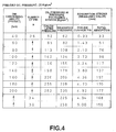
- Fig. 4 is a table in which die cushion ability, the number of pressured die cushion pins, oil pressure in the die cushion pin pressure equalizing system, and absorption stroke are shown when the preload oil pressure P0 is 25 kg/cm2.
- Fig. 5 shows the above items are shown when the preload oil pressure P0 is 75 kg/cm2.
- Fig. 6 is a graph prepared by plotting the relationship between the total die cushion pin absorption stroke ⁇ and oil pressure P in the die cushion pin pressure equalizing system when the preload oil pressure P0 is 25 kg/cm2 and 75 kg/cm2.
- the relationship between the total absorption stroke and the oil pressure in the die cushion pin pressure equalizing system is obtained for the preload oil pressure P0 is P01 and P02 as shown in Fig. 1.
- reference character PD designates a stable oil pressure value shown in Fig. 2.
- the total absorption stroke at the stable oil pressure PD is shifted from L2 to L1.
- the total absorption stroke is shortened by L2 - L1. This makes it possible to prevent the bottoming of the plunger of the pressure equalizing hydraulic cylinder 11.
- the total absorption stroke of the die cushion pin pressure equalizing system at the stable oil pressure PD is shortened by raising the preload oil pressure by an adequate quantity, whereby the bottoming of the plunger is prevented.
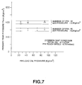
- Fig. 7 shows a result of an experiment and illustrates the relationship between the preload oil pressure P0 and the primary peak pressure Pmax for the total quantity of hydraulic oil in the die cushion pin pressure equalizing system of 6 liters and the pin touch speed of 0.757 m/sec under the conditions that the number of used die cushion pins is 20 and the air pressure is 2.0 kg/cm2, and the number of die cushion pins is 40 and the air pressure is 6.2 kg/cm2.
- the primary peak pressure Pmax is plotted substantially in parallel with the abscissa of the graph, which shows that the primary peak pressure Pmax is not affected by the change in the preload pressure.
- the method of the present invention can be practiced without incurring the fatigue crack or breakage at the stopper portion of the plunger in the pressure equalizing hydraulic cylinder 11 which will occur due to the raising of the preload oil pressure as mentioned above.
- the present invention is advantageously employable for press-drawing by using a press machine equipped with a die cushion pin pressure equalizing system.
- bottoming of the plungers of the hydraulic cylinders arranged in the die cushion pin equalizing system can reliably be prevented.
Landscapes
- Engineering & Computer Science (AREA)
- Mechanical Engineering (AREA)
- Shaping Metal By Deep-Drawing, Or The Like (AREA)
- Presses And Accessory Devices Thereof (AREA)
Applications Claiming Priority (4)
| Application Number | Priority Date | Filing Date | Title |
|---|---|---|---|
| JP14492491A JP3255174B2 (ja) | 1991-06-17 | 1991-06-17 | ダイクッションピン均圧化装置のプランジャー底付け防止方法 |
| JP144924/91 | 1991-06-17 | ||
| JP14492491 | 1991-06-17 | ||
| PCT/JP1992/000775 WO1992022391A1 (fr) | 1991-06-17 | 1992-06-17 | Procede utilise dans un systeme d'egalisation de la pression s'exerçant sur les broches de serre-flans, pour eviter que les pistons n'aillent en butee |
Publications (3)
| Publication Number | Publication Date |
|---|---|
| EP0592670A1 true EP0592670A1 (de) | 1994-04-20 |
| EP0592670A4 EP0592670A4 (de) | 1995-02-15 |
| EP0592670B1 EP0592670B1 (de) | 1999-08-25 |
Family
ID=15373388
Family Applications (1)
| Application Number | Title | Priority Date | Filing Date |
|---|---|---|---|
| EP92912641A Expired - Lifetime EP0592670B1 (de) | 1991-06-17 | 1992-06-17 | Verfahren zum verhindern des eindringens von stösseln in den boden in einem polsterstiftdruckausgleichssystem |
Country Status (5)
| Country | Link |
|---|---|
| EP (1) | EP0592670B1 (de) |
| JP (1) | JP3255174B2 (de) |
| CA (1) | CA2111671C (de) |
| DE (1) | DE69229863T2 (de) |
| WO (1) | WO1992022391A1 (de) |
Family Cites Families (2)
| Publication number | Priority date | Publication date | Assignee | Title |
|---|---|---|---|---|
| JPH0239622Y2 (de) * | 1985-06-20 | 1990-10-24 | ||
| JPS6220711U (de) * | 1985-07-19 | 1987-02-07 |
-
1991
- 1991-06-17 JP JP14492491A patent/JP3255174B2/ja not_active Expired - Lifetime
-
1992
- 1992-06-17 WO PCT/JP1992/000775 patent/WO1992022391A1/ja not_active Ceased
- 1992-06-17 EP EP92912641A patent/EP0592670B1/de not_active Expired - Lifetime
- 1992-06-17 CA CA002111671A patent/CA2111671C/en not_active Expired - Lifetime
- 1992-06-17 DE DE69229863T patent/DE69229863T2/de not_active Expired - Lifetime
Non-Patent Citations (2)
| Title |
|---|
| No further relevant documents disclosed * |
| See also references of WO9222391A1 * |
Also Published As
| Publication number | Publication date |
|---|---|
| WO1992022391A1 (fr) | 1992-12-23 |
| JP3255174B2 (ja) | 2002-02-12 |
| CA2111671C (en) | 2002-09-17 |
| CA2111671A1 (en) | 1992-12-23 |
| DE69229863T2 (de) | 2000-04-27 |
| EP0592670B1 (de) | 1999-08-25 |
| DE69229863D1 (de) | 1999-09-30 |
| EP0592670A4 (de) | 1995-02-15 |
| JPH04371325A (ja) | 1992-12-24 |
Similar Documents
| Publication | Publication Date | Title |
|---|---|---|
| EP0531140B1 (de) | Hydraulische Polsteranordnung für eine Presse mit verstellbarer hydraulischer Energieversorgung zum Einstellen des Anfangdruckes der Zylinder der Druckbolzen | |
| US4553795A (en) | Mold supporting arrangement | |
| JP3565679B2 (ja) | 板金成形用油圧プレス機械 | |
| US5735201A (en) | Apparatus including mutually communicating hydraulic cylinders for even distribution of blank-holding force on pressing machine | |
| US6250216B1 (en) | Press deflection controller and method of controlling press deflection | |
| US5660074A (en) | Method of selecting a preload oil pressure valve for a die cushion pin pressure equalizing system of a press machine | |
| JP3295115B2 (ja) | ハイドロエラスティックな深絞り装置 | |
| JPS592569B2 (ja) | 平板折り曲げプレス | |
| EP0592670A1 (de) | Verfahren zum verhindern des eindringens von stösseln in den boden in einem polsterstiftdruckausgleichssystem | |
| EP0384340B1 (de) | Vorrichtung zum Anritzen kornorientierter Elektrostahlbänder | |
| JP2727954B2 (ja) | プレス装置 | |
| US20040094046A1 (en) | Cushion pin, wear plate, load supporting device, die cushion, press machine and pressing method | |
| KR20010064338A (ko) | 상하 분할식 튜브 하이드로포밍성 평가 장치 및 이에적합한 평가 방법 | |
| JP3943686B2 (ja) | プリント基板打抜き加工装置 | |
| US4697338A (en) | Device for preparing a cutting tool | |
| JP2003136299A (ja) | プレス金型機構に内蔵の油圧式クッション装置 | |
| JPH0239622Y2 (de) | ||
| CN119747442B (zh) | 一种履带整形装置 | |
| US2112012A (en) | Press | |
| JPH0224491Y2 (de) | ||
| CN223382365U (zh) | 一种压机用上气垫分区控制装置 | |
| CN216127806U (zh) | 一种超精密数控压片机 | |
| JPS6161918B2 (de) | ||
| JPS632182Y2 (de) | ||
| CN111731002A (zh) | 一种多工件增压打钢印装置 |
Legal Events
| Date | Code | Title | Description |
|---|---|---|---|
| PUAI | Public reference made under article 153(3) epc to a published international application that has entered the european phase |
Free format text: ORIGINAL CODE: 0009012 |
|
| 17P | Request for examination filed |
Effective date: 19931218 |
|
| AK | Designated contracting states |
Kind code of ref document: A1 Designated state(s): DE FR GB IT |
|
| A4 | Supplementary search report drawn up and despatched |
Effective date: 19940104 |
|
| AK | Designated contracting states |
Kind code of ref document: A4 Designated state(s): DE FR GB IT |
|
| 17Q | First examination report despatched |
Effective date: 19970211 |
|
| GRAG | Despatch of communication of intention to grant |
Free format text: ORIGINAL CODE: EPIDOS AGRA |
|
| GRAG | Despatch of communication of intention to grant |
Free format text: ORIGINAL CODE: EPIDOS AGRA |
|
| GRAG | Despatch of communication of intention to grant |
Free format text: ORIGINAL CODE: EPIDOS AGRA |
|
| GRAH | Despatch of communication of intention to grant a patent |
Free format text: ORIGINAL CODE: EPIDOS IGRA |
|
| GRAH | Despatch of communication of intention to grant a patent |
Free format text: ORIGINAL CODE: EPIDOS IGRA |
|
| GRAA | (expected) grant |
Free format text: ORIGINAL CODE: 0009210 |
|
| AK | Designated contracting states |
Kind code of ref document: B1 Designated state(s): DE FR GB IT |
|
| PG25 | Lapsed in a contracting state [announced via postgrant information from national office to epo] |
Ref country code: IT Free format text: LAPSE BECAUSE OF FAILURE TO SUBMIT A TRANSLATION OF THE DESCRIPTION OR TO PAY THE FEE WITHIN THE PRESCRIBED TIME-LIMIT;WARNING: LAPSES OF ITALIAN PATENTS WITH EFFECTIVE DATE BEFORE 2007 MAY HAVE OCCURRED AT ANY TIME BEFORE 2007. THE CORRECT EFFECTIVE DATE MAY BE DIFFERENT FROM THE ONE RECORDED. Effective date: 19990825 |
|
| RAP1 | Party data changed (applicant data changed or rights of an application transferred) |
Owner name: TOYOTA JIDOSHA KABUSHIKI KAISHA |
|
| REF | Corresponds to: |
Ref document number: 69229863 Country of ref document: DE Date of ref document: 19990930 |
|
| ET | Fr: translation filed | ||
| PLBE | No opposition filed within time limit |
Free format text: ORIGINAL CODE: 0009261 |
|
| STAA | Information on the status of an ep patent application or granted ep patent |
Free format text: STATUS: NO OPPOSITION FILED WITHIN TIME LIMIT |
|
| 26N | No opposition filed | ||
| REG | Reference to a national code |
Ref country code: GB Ref legal event code: IF02 |
|
| PGFP | Annual fee paid to national office [announced via postgrant information from national office to epo] |
Ref country code: FR Payment date: 20110621 Year of fee payment: 20 |
|
| PGFP | Annual fee paid to national office [announced via postgrant information from national office to epo] |
Ref country code: GB Payment date: 20110615 Year of fee payment: 20 |
|
| PGFP | Annual fee paid to national office [announced via postgrant information from national office to epo] |
Ref country code: DE Payment date: 20110615 Year of fee payment: 20 |
|
| REG | Reference to a national code |
Ref country code: DE Ref legal event code: R071 Ref document number: 69229863 Country of ref document: DE |
|
| REG | Reference to a national code |
Ref country code: DE Ref legal event code: R071 Ref document number: 69229863 Country of ref document: DE |
|
| REG | Reference to a national code |
Ref country code: GB Ref legal event code: PE20 Expiry date: 20120616 |
|
| PG25 | Lapsed in a contracting state [announced via postgrant information from national office to epo] |
Ref country code: DE Free format text: LAPSE BECAUSE OF EXPIRATION OF PROTECTION Effective date: 20120619 |
|
| PG25 | Lapsed in a contracting state [announced via postgrant information from national office to epo] |
Ref country code: GB Free format text: LAPSE BECAUSE OF EXPIRATION OF PROTECTION Effective date: 20120616 |