EP0592749A1 - Procédé de tissage et métier à tisser pour la fabrication de tissu-éponge - Google Patents
Procédé de tissage et métier à tisser pour la fabrication de tissu-éponge Download PDFInfo
- Publication number
- EP0592749A1 EP0592749A1 EP92810794A EP92810794A EP0592749A1 EP 0592749 A1 EP0592749 A1 EP 0592749A1 EP 92810794 A EP92810794 A EP 92810794A EP 92810794 A EP92810794 A EP 92810794A EP 0592749 A1 EP0592749 A1 EP 0592749A1
- Authority
- EP
- European Patent Office
- Prior art keywords
- stop
- fabric
- shed
- threads
- weft
- Prior art date
- Legal status (The legal status is an assumption and is not a legal conclusion. Google has not performed a legal analysis and makes no representation as to the accuracy of the status listed.)
- Withdrawn
Links
Images


Classifications
-
- D—TEXTILES; PAPER
- D03—WEAVING
- D03D—WOVEN FABRICS; METHODS OF WEAVING; LOOMS
- D03D39/00—Pile-fabric looms
- D03D39/22—Terry looms
-
- D—TEXTILES; PAPER
- D03—WEAVING
- D03D—WOVEN FABRICS; METHODS OF WEAVING; LOOMS
- D03D41/00—Looms not otherwise provided for, e.g. for weaving chenille yarn; Details peculiar to these looms
- D03D41/005—Linear-shed multiphase looms
Definitions
- the invention relates to a weaving method according to the preamble of claim 1 and to a weaving machine for carrying out the method.
- terry weaving machines For the production of terry cloth, for example for bath towels and the like, terry weaving machines are used which work with two separate warp thread systems, a basic warp thread system and a pile warp thread system.
- two warp thread trees associated with the two warp thread systems are stored in the weaving machine frame, which are controlled in such a way that the two warp thread systems have a different warp thread tension.
- the warp threads of the basic warp thread system are kept taut with constant, comparatively high thread tension, while the warp threads of the pile warp thread system are loosely held with low tension in such a way that they can easily give way when the loop is formed.
- weft threads When weaving, for example, three or four weft threads are always inserted with the appropriate binding, but are not fully struck against the fabric edge by appropriately setting the limit stops of the reed. Rather, they are simply moved in their respective shed near the edge of the fabric. Only after the third or fourth weft thread has been inserted is a full weft stop made up to the edge of the fabric, which means that the warp threads of the pile warp thread system which are less taut and loosely resilient are held over the taut ones Basic warp threads are pushed away and loops form together. In conventional single-system weaving machines, the weft threading is usually carried out with a sley, so that these terry weaving machines are usually equipped with devices that enable different weft threading through the reed.
- the weaving performance of such known weaving machines with a weft insertion system using a rapier, projectile or air is limited.
- the object of the invention is therefore to provide a weaving process that allows terry cloth or loop fabric in general to be produced much more efficiently and thus more economically.
- the row shed weaving machine has the advantage that the weft thread is beaten at the same time over the entire width of the fabric by means of stop slats. This leads to a very uniform fabric, in particular to a very uniform formation of the loops.
- the weaving machine according to the invention for the production of terry fabrics allows any weave and any selectable loop length and density to be made, whereby the production of terry fabrics with color patterning is also possible through the appropriate choice of basic warp threads, pile warp threads and weft threads.
- a row shed weaving machine consists of a rotating weaving rotor, on the surface of which guide elements are arranged, which are regularly spaced in the direction of rotation and which are arranged next to one another in alignment across the width of the fabric.
- the warp threads that is to say the basic warp threads and the pile warp threads, are inserted by means of laying elements in high and low points of the shed forming means in such a way that shed weaves are created through which the weft thread can be inserted.
- one weft channel is usually left in the shedding means, so that the weft thread can be inserted into the open shed.
- the formerly open shed begins to close against the fabric edge during the movement, the weft moves more slowly than the weft channel and is simultaneously raised to a higher path with respect to the center of rotation of the weaving rotor.
- Lifting combs which either form part of the shedding means or are designed as separate lamellae, comb through the warp threads in the direction of rotation of the weaving rotor, and convey the slow moving weft to a position that is at a defined distance from the fabric edge, which is known as a partial stop.
- a full stop takes place by means of stop lamellae distributed over the entire fabric width in such a way that all weft threads spaced from the fabric edge are struck on the latter, the base warp threads being tensioned tightly during the attack the pile warp threads are kept loose, so that the pile warp threads are attached a loop formation occurs around the fabric edge.
- stop lamellae distributed over the entire fabric width in such a way that all weft threads spaced from the fabric edge are struck on the latter, the base warp threads being tensioned tightly during the attack the pile warp threads are kept loose, so that the pile warp threads are attached a loop formation occurs around the fabric edge.
- a distinction must therefore be made between a partial stop and a full stop. This can be achieved, for example, by designing the stop slats differently.
- Full stop slats are designed, for example, in such a way that they project the partial stop slats in a radial direction with respect to the center of rotation of the weaving rotor, which enables the full stop slats to act on the weft threads over a larger angular range on their rotating path and thus to effect a full stop.
- This configuration of partial stop and full stop slats has the disadvantage, when operated with the described method, that only loop fabric can be produced with a weaving rotor equipped in this way, the number of weft threads entered up to a full stop with a corresponding loop formation due to the sequence of full stop and Partial stop slats is fixed.
- a change to other fabrics or other types of weave is connected with an exchange of the lamellae or the rotor and is correspondingly complex.
- a full stop with a corresponding loop formation in the tissue can be achieved, for example, by periodically moving the tissue edge closer or deeper to the stop slats.
- the fabric edge and the associated fabric as well as the warp threads are moved back and forth in their direction of travel with movement means at least in the area spanning the weaving rotor in such a way that the fabric edge comes to lie deeper between the stop slats when a full stop is to be carried out , and the Fabric edge comes further from the center of rotation of the rotor when the weft threads are to be struck at a certain distance from the fabric edge.
- This attachment method with corresponding attachment slats offers the advantage that both terry fabrics and the usual fabrics can be produced with the same weaving rotor without having to change over. Another advantage is that the number of inserted weft threads up to a full weft thread stop can be varied as desired without changes to the weaving rotor.
- Row shed weaving machine consisting of a weaving rotor with combs, which comb through the warp threads, which are inserted by laying elements into shed-forming high and low points of shed training means, in the direction of rotation up to the area of the fabric edge.
- the warp threads are composed of a basic warp thread system with basic warp threads that are under a relatively high thread tension and a pile warp thread system with pile warp threads that are held in a yielding manner by means of a rocker.
- Partial stop slats convey each individual weft thread entered in an open shed near the fabric edge while maintaining a predeterminable distance.
- Full stop slats periodically strike all spaced weft threads against the fabric edge in such a way that pile loops form in the pile warp threads.
- the terry fabric produced in this way is drawn off through a fabric tree.
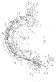
- Fig. 1 shows a row shed loom on whose weaving rotor 1 are arranged in the direction of rotation 12 at an angle ⁇ spaced shed forming means 2, which are lamella-like, and which are aligned alongside each other across the width of the fabric.
- Laying elements 5a-5d lay the warp threads 6 - 9, preferably by movements running parallel to the axis of rotation 1a of the weaving rotor 1, into shed-forming high and low points 2a, 2b of the shedding means 2.
- the shed forming means 2 usually has a recess in which the weft thread 10 can be entered over the width of the fabric, usually parallel or approximately parallel to the axis of rotation 1 a of the weaving rotor 1.
- the shed forming means 2 have a weft channel 3 and fluid nozzles 4 with an associated feed channel 11 for fluids, so that the weft thread 10 by means of a fluid such as air can be entered. After the weft thread has been inserted, the weft thread 10 is to be fed to the fabric 23 or the fabric edge 18 in order to be attached to it later.
- stop slats 14 are arranged between the shed forming elements 2, which, like the shed forming means 2, are aligned over the fabric width, or the stop slats 14, as shown in the present exemplary embodiment, form part of the shed forming means 2.
- the edge of the stop lamella 14 facing the fabric edge 18 is designed as a stop edge 13.
- the open shed 22 formed between the warp threads 6 - 9 narrows increasingly towards the fabric edge 18 due to the warp threads 6 - 9 emerging from the weaving rotor 1. This has the effect that the rotational speed of the weft thread 10 is increasingly determined by the speed of movement of the warp threads 6-9.
- the weft thread 10 therefore moves more slowly than the weft channel 3 and is simultaneously raised toward the fabric edge with respect to the center of rotation 1a of the weaving rotor 1.
- the weft thread 10 is then pushed into a defined position by the stop edge 13 of the subsequent stop lamella 14.
- the partial stop slats 2c move the weft thread 10 in the illustrated embodiment into a position at a defined distance from the fabric edge 18.
- the full stop slats 2d the outermost movement path 16 of which is shown with respect to the center of rotation 1a, cause a full stop of all of the fabric edge 18 spaced weft threads 10 on the fabric edge 18.
- the base warp threads 8, 9 are kept very taut, whereas the pile warp threads 6, 7 are kept loose and yielding, so that loop formation occurs in the pile chains 8, 9 and thus pile loops 19 arise in the area of the fabric edge 18 of the fabric 23.
- tissue guiding means 15 can be moved back and forth in the withdrawal direction d and / or transversely to the withdrawal direction c.
- the tissue guiding means 15 can be moved away from the center of rotation 1a in the direction c of the full stop in order to reduce or avoid contact between pile loops 19 and full stop slats 2d or partial stop slats 2c.
- the fabric guiding means 15 can be moved before each full stop, for example in the direction of movement c, towards the center of rotation 1a of the weaving rotor 1 in order to increase the angle of rotation during which a stop blade acts on a weft thread 10.
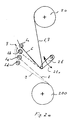
- FIG. 2a shows a pile warp beam 20 and a base warp beam 200 with part of the fabric conveying means that are usually required.
- the base warp threads 8 and 9 are inserted into the shed forming means 2 by the laying elements 5c and 5d and are held relatively taut by the base warp beam 200.
- the pile warp threads 6, 7 are inserted by the laying elements 5a, 5b, and are held loose, yielding by the pile warp beam 20 and by the rocker 21 movable in the direction 21a.
- pile warp threads 6, 7 must be given in briefly, depending on the attachment method during the formation of the loop, which is done by a correspondingly yielding movement 21a of the rocker 21.
- the base warp threads 8, 9 are kept relatively taut, so that loop formation only occurs in the pile warp threads 6, 7.
- FIG. 2b shows a further pile warp beam 20 and a basic warp beam 200 with a selection of fabric conveying means, whereby further fabric conveying means are usually used.
- the base warp threads 8, 9 are inserted into the shed forming means 2 by the laying elements 5c, 5d and are usually taut. However, if the base warp threads 8, 9 are periodically moved back and forth in the direction of movement f with each full stop, as described with FIG. 1, a rocker 210 with the direction of movement 210a is suitable for this purpose. The base warp threads 8, 9 can thus be moved back and forth in the direction of movement f without changing the basic tension of the warp threads 8, 9.
- the base warp threads 8, 9 back and forth in the direction of movement f moved it may prove necessary to also move the pile warp threads 6, 7 back and forth in the direction of movement f.
- the pile warp threads must therefore be kept yielding by the rocker 21 during the full stop. If the base warp threads 8, 9 are moved counter to the direction of rotation 12 of the weaving rotor 1, it may prove necessary to also move the pile warp threads 6, 7 in the same direction. For this purpose, the pile warp threads 6, 7 must be held in place by the pile warp beam 20, and the pile warp threads 6, 7 must be moved counter to the direction of rotation 12 by the rocker 21.
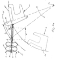
- FIG. 3a shows the weft threads 10 striking against the fabric edge 18.
- the two previously inserted weft threads 10 were pushed into a position by partial stop slats 2c rotating in the direction of rotation 12, which is approximately a distance b from the fabric edge 18 having.
- the third of the weft threads 10 was pushed by the shedding means 2 or its stop lamella 14 with stop edge 13 up to the other two weft threads 10.
- the full stop begins by the stop blade 14 with the full stop blade 2d continuing to rotate in the direction of rotation 12 of the weaving rotor 1, and thereby the weft threads 10 during an angle of rotation ⁇ through the stop edge 13 by approximately the distance b are conveyed to the fabric edge 18.
- the base warp threads 8, 9 are under a relatively high tension, whereas the pile warp threads 6, 7 are held loosely, so that pile loops 19 form in these warp threads during the full stop. This creates a terry cloth 23.
- the stop slats 14 lie parallel to one another along the axis of rotation 1a over the width of the fabric, so that the full stop with loop formation takes place simultaneously over the entire width of the fabric.
- FIG. 3b shows a further method for achieving a full stop, in that the partial stop slats 2c, as already described in FIG. 3a, convey weft threads in the vicinity of the fabric edge 18, the distance from the fabric edge being approximately b.
- the full stop of the weft threads 10 with loop formation on the fabric edge 18 in the present example does not take place with a full stop blade 2d but with a partial stop blade 2c, in that the fabric 23 and thus also the warp threads 6-9 immediately before a full stop by the distance b opposite to the direction of rotation 12 of the weaving rotor 1 is displaced, which enables the partial stop slats 2c to strike the weft threads 10 against the fabric edge 18.
- the partial weft slat 2c has just carried out a full weft of the weft threads 10 on the fabric edge 18.
- the fabric 23 is then removed from the weaving rotor 1 again by the distance b in the direction of rotation 12c, so that the subsequent partial stop slats 2c push the weft threads 10 into a position which is approximately a distance b from the fabric edge 18.
Landscapes
- Engineering & Computer Science (AREA)
- Textile Engineering (AREA)
- Looms (AREA)
Priority Applications (1)
| Application Number | Priority Date | Filing Date | Title |
|---|---|---|---|
| EP92810794A EP0592749A1 (fr) | 1992-10-16 | 1992-10-16 | Procédé de tissage et métier à tisser pour la fabrication de tissu-éponge |
Applications Claiming Priority (1)
| Application Number | Priority Date | Filing Date | Title |
|---|---|---|---|
| EP92810794A EP0592749A1 (fr) | 1992-10-16 | 1992-10-16 | Procédé de tissage et métier à tisser pour la fabrication de tissu-éponge |
Publications (1)
| Publication Number | Publication Date |
|---|---|
| EP0592749A1 true EP0592749A1 (fr) | 1994-04-20 |
Family
ID=8212008
Family Applications (1)
| Application Number | Title | Priority Date | Filing Date |
|---|---|---|---|
| EP92810794A Withdrawn EP0592749A1 (fr) | 1992-10-16 | 1992-10-16 | Procédé de tissage et métier à tisser pour la fabrication de tissu-éponge |
Country Status (1)
| Country | Link |
|---|---|
| EP (1) | EP0592749A1 (fr) |
Cited By (4)
| Publication number | Priority date | Publication date | Assignee | Title |
|---|---|---|---|---|
| EP0859075A1 (fr) | 1997-02-08 | 1998-08-19 | Günne Webmaschinenfabrik GmbH & Co. KG | Utilisation d'un métier pour tissu éponge |
| US5904186A (en) * | 1995-06-02 | 1999-05-18 | Sulzer Rueti Ag | Series shed weaving machine for weaving multiple web panels on a single rotor |
| WO2003089704A1 (fr) * | 2002-04-22 | 2003-10-30 | Picanol N.V., Naamloze Vennootschap | Metier a tisser et procede de fabrication d'un tissu avec ledit metier |
| CN110820140A (zh) * | 2019-12-12 | 2020-02-21 | 江苏莱纳多智能装备有限公司 | 一种两侧布置的打纬引纬传动机构 |
Citations (2)
| Publication number | Priority date | Publication date | Assignee | Title |
|---|---|---|---|---|
| FR2156215A1 (fr) * | 1971-10-11 | 1973-05-25 | Sulzer Ag | |
| EP0013321A1 (fr) * | 1978-12-07 | 1980-07-23 | Maschinenfabrik Sulzer-Rüti Ag | Métier à tisser multiphasé à foule linéaire avec un rotor de tissage |
-
1992
- 1992-10-16 EP EP92810794A patent/EP0592749A1/fr not_active Withdrawn
Patent Citations (2)
| Publication number | Priority date | Publication date | Assignee | Title |
|---|---|---|---|---|
| FR2156215A1 (fr) * | 1971-10-11 | 1973-05-25 | Sulzer Ag | |
| EP0013321A1 (fr) * | 1978-12-07 | 1980-07-23 | Maschinenfabrik Sulzer-Rüti Ag | Métier à tisser multiphasé à foule linéaire avec un rotor de tissage |
Cited By (5)
| Publication number | Priority date | Publication date | Assignee | Title |
|---|---|---|---|---|
| US5904186A (en) * | 1995-06-02 | 1999-05-18 | Sulzer Rueti Ag | Series shed weaving machine for weaving multiple web panels on a single rotor |
| EP0859075A1 (fr) | 1997-02-08 | 1998-08-19 | Günne Webmaschinenfabrik GmbH & Co. KG | Utilisation d'un métier pour tissu éponge |
| WO2003089704A1 (fr) * | 2002-04-22 | 2003-10-30 | Picanol N.V., Naamloze Vennootschap | Metier a tisser et procede de fabrication d'un tissu avec ledit metier |
| CN110820140A (zh) * | 2019-12-12 | 2020-02-21 | 江苏莱纳多智能装备有限公司 | 一种两侧布置的打纬引纬传动机构 |
| CN110820140B (zh) * | 2019-12-12 | 2024-04-26 | 江苏莱纳多智能装备有限公司 | 一种两侧布置的打纬引纬传动机构 |
Similar Documents
| Publication | Publication Date | Title |
|---|---|---|
| DE2642734C3 (de) | Lamellenkamm einer Düsenwebmaschine | |
| EP3347512B1 (fr) | Metier a tisser destine a la fabrication de produits tisses dotes d'un fil a poser ou a tricoter incorpore | |
| CH635625A5 (de) | Schuetzenlose webmaschine zur herstellung von geweben mit musterungsrapport. | |
| DE3200638A1 (de) | Schuetzenlose webmaschine | |
| WO1994026964A1 (fr) | Metier a rubans comportant une aiguille d'insertion de trame | |
| CH646213A5 (de) | Luftduesenwebmaschine. | |
| DE69811186T2 (de) | Verfahren zur Herstellung eines Polgewebes mit groben Kettpolfaden | |
| CH653060A5 (de) | Schusseintragskanal an einer duesenwebmaschine. | |
| DE2949765A1 (de) | Weberschiffchenfreier webstuhl | |
| EP1255885B1 (fr) | Procede pour devier une portee de fils de chaine pendant le tissage, et metier a tisser | |
| EP0022226B1 (fr) | Métier à tisser à buses | |
| DE2724923C3 (de) | Zwillings-Düsen-Webmaschine | |
| EP0155431A1 (fr) | Procédé d'insertion de fil de trame pour un métier à tisser et métier à tisser pour réaliser ce procédé | |
| DE3415781A1 (de) | Fuehrungssystem zum eintragen von schussfaeden fuer doppelwebmaschinen und webmaschine mit einem derartigen system | |
| DE102005028124A1 (de) | Frottierwebmaschine | |
| CH623872A5 (en) | Shuttleless weaving machine. | |
| DE60007009T2 (de) | Verfahren zum Weben von Polgewebe auf einer Greifer-Axminster Webmaschine und nach diesem Verfahren hergestelltes Gewebe | |
| EP0570330B1 (fr) | Métier à tisser multiphase à foule linéaire | |
| DE2900186C2 (de) | Schußfadenwechselvorrichtung einer Düsenwebmaschine | |
| DE2460737C3 (de) | Vorrichtung in einer Nadelwebmaschine zur Herstellung von Bandgeweben mit Schußschlaufen | |
| DE3248557C2 (fr) | ||
| EP0053217A1 (fr) | Lamelle de guidage pour la formation du canal de guidage dans un métier à tisser | |
| EP0368799A1 (fr) | Métier à tisser avec support de tissu | |
| EP0379843A2 (fr) | Assemblage peigne-ensouple à double fonction et son utilisation pour machines à tisser | |
| DE2221282C3 (de) | Webmaschine zur Herstellung von Frottiergewebe |
Legal Events
| Date | Code | Title | Description |
|---|---|---|---|
| PUAI | Public reference made under article 153(3) epc to a published international application that has entered the european phase |
Free format text: ORIGINAL CODE: 0009012 |
|
| AK | Designated contracting states |
Kind code of ref document: A1 Designated state(s): AT BE CH DE DK ES FR GB GR IE IT LI LU MC NL PT SE |
|
| RBV | Designated contracting states (corrected) |
Designated state(s): BE DE FR IT |
|
| 18D | Application deemed to be withdrawn |
Effective date: 19941021 |