EP0592768B1 - A process for co-molding a metal insert - Google Patents
A process for co-molding a metal insert Download PDFInfo
- Publication number
- EP0592768B1 EP0592768B1 EP93109956A EP93109956A EP0592768B1 EP 0592768 B1 EP0592768 B1 EP 0592768B1 EP 93109956 A EP93109956 A EP 93109956A EP 93109956 A EP93109956 A EP 93109956A EP 0592768 B1 EP0592768 B1 EP 0592768B1
- Authority
- EP
- European Patent Office
- Prior art keywords
- cavities
- insert
- regions
- blank holder
- mold
- Prior art date
- Legal status (The legal status is an assumption and is not a legal conclusion. Google has not performed a legal analysis and makes no representation as to the accuracy of the status listed.)
- Expired - Lifetime
Links
- 239000002184 metal Substances 0.000 title claims description 22
- 238000000034 method Methods 0.000 title claims description 16
- 238000013037 co-molding Methods 0.000 title claims description 11
- 229920003023 plastic Polymers 0.000 claims description 31
- 239000004033 plastic Substances 0.000 claims description 31
- 239000000463 material Substances 0.000 claims description 20
- 230000000452 restraining effect Effects 0.000 claims description 16
- 238000002347 injection Methods 0.000 claims description 13
- 239000007924 injection Substances 0.000 claims description 13
- 239000012530 fluid Substances 0.000 claims description 12
- 238000004519 manufacturing process Methods 0.000 claims description 5
- 230000002706 hydrostatic effect Effects 0.000 claims description 4
- 230000008878 coupling Effects 0.000 claims description 2
- 238000010168 coupling process Methods 0.000 claims description 2
- 238000005859 coupling reaction Methods 0.000 claims description 2
- 238000006073 displacement reaction Methods 0.000 claims description 2
- 238000000465 moulding Methods 0.000 claims description 2
- 238000000926 separation method Methods 0.000 claims 2
- 239000007787 solid Substances 0.000 claims 2
- 238000001816 cooling Methods 0.000 claims 1
- 230000003068 static effect Effects 0.000 claims 1
- 230000000694 effects Effects 0.000 description 2
- 230000015572 biosynthetic process Effects 0.000 description 1
- 239000000428 dust Substances 0.000 description 1
- XLYOFNOQVPJJNP-UHFFFAOYSA-N water Substances O XLYOFNOQVPJJNP-UHFFFAOYSA-N 0.000 description 1
Images


Classifications
-
- H—ELECTRICITY
- H05—ELECTRIC TECHNIQUES NOT OTHERWISE PROVIDED FOR
- H05K—PRINTED CIRCUITS; CASINGS OR CONSTRUCTIONAL DETAILS OF ELECTRIC APPARATUS; MANUFACTURE OF ASSEMBLAGES OF ELECTRICAL COMPONENTS
- H05K3/00—Apparatus or processes for manufacturing printed circuits
- H05K3/10—Apparatus or processes for manufacturing printed circuits in which conductive material is applied to the insulating support in such a manner as to form the desired conductive pattern
- H05K3/20—Apparatus or processes for manufacturing printed circuits in which conductive material is applied to the insulating support in such a manner as to form the desired conductive pattern by affixing prefabricated conductor pattern
- H05K3/202—Apparatus or processes for manufacturing printed circuits in which conductive material is applied to the insulating support in such a manner as to form the desired conductive pattern by affixing prefabricated conductor pattern using self-supporting metal foil pattern
-
- B—PERFORMING OPERATIONS; TRANSPORTING
- B29—WORKING OF PLASTICS; WORKING OF SUBSTANCES IN A PLASTIC STATE IN GENERAL
- B29C—SHAPING OR JOINING OF PLASTICS; SHAPING OF MATERIAL IN A PLASTIC STATE, NOT OTHERWISE PROVIDED FOR; AFTER-TREATMENT OF THE SHAPED PRODUCTS, e.g. REPAIRING
- B29C45/00—Injection moulding, i.e. forcing the required volume of moulding material through a nozzle into a closed mould; Apparatus therefor
- B29C45/14—Injection moulding, i.e. forcing the required volume of moulding material through a nozzle into a closed mould; Apparatus therefor incorporating preformed parts or layers, e.g. injection moulding around inserts or for coating articles
- B29C45/14065—Positioning or centering articles in the mould
- B29C45/14073—Positioning or centering articles in the mould using means being retractable during injection
-
- B—PERFORMING OPERATIONS; TRANSPORTING
- B29—WORKING OF PLASTICS; WORKING OF SUBSTANCES IN A PLASTIC STATE IN GENERAL
- B29C—SHAPING OR JOINING OF PLASTICS; SHAPING OF MATERIAL IN A PLASTIC STATE, NOT OTHERWISE PROVIDED FOR; AFTER-TREATMENT OF THE SHAPED PRODUCTS, e.g. REPAIRING
- B29C45/00—Injection moulding, i.e. forcing the required volume of moulding material through a nozzle into a closed mould; Apparatus therefor
- B29C45/14—Injection moulding, i.e. forcing the required volume of moulding material through a nozzle into a closed mould; Apparatus therefor incorporating preformed parts or layers, e.g. injection moulding around inserts or for coating articles
- B29C45/1418—Injection moulding, i.e. forcing the required volume of moulding material through a nozzle into a closed mould; Apparatus therefor incorporating preformed parts or layers, e.g. injection moulding around inserts or for coating articles the inserts being deformed or preformed, e.g. by the injection pressure
- B29C45/14221—Injection moulding, i.e. forcing the required volume of moulding material through a nozzle into a closed mould; Apparatus therefor incorporating preformed parts or layers, e.g. injection moulding around inserts or for coating articles the inserts being deformed or preformed, e.g. by the injection pressure by tools, e.g. cutting means
-
- B—PERFORMING OPERATIONS; TRANSPORTING
- B29—WORKING OF PLASTICS; WORKING OF SUBSTANCES IN A PLASTIC STATE IN GENERAL
- B29C—SHAPING OR JOINING OF PLASTICS; SHAPING OF MATERIAL IN A PLASTIC STATE, NOT OTHERWISE PROVIDED FOR; AFTER-TREATMENT OF THE SHAPED PRODUCTS, e.g. REPAIRING
- B29C45/00—Injection moulding, i.e. forcing the required volume of moulding material through a nozzle into a closed mould; Apparatus therefor
- B29C45/14—Injection moulding, i.e. forcing the required volume of moulding material through a nozzle into a closed mould; Apparatus therefor incorporating preformed parts or layers, e.g. injection moulding around inserts or for coating articles
- B29C45/14065—Positioning or centering articles in the mould
- B29C45/14073—Positioning or centering articles in the mould using means being retractable during injection
- B29C2045/14081—Positioning or centering articles in the mould using means being retractable during injection centering means retracted by the injection pressure
-
- B—PERFORMING OPERATIONS; TRANSPORTING
- B29—WORKING OF PLASTICS; WORKING OF SUBSTANCES IN A PLASTIC STATE IN GENERAL
- B29C—SHAPING OR JOINING OF PLASTICS; SHAPING OF MATERIAL IN A PLASTIC STATE, NOT OTHERWISE PROVIDED FOR; AFTER-TREATMENT OF THE SHAPED PRODUCTS, e.g. REPAIRING
- B29C45/00—Injection moulding, i.e. forcing the required volume of moulding material through a nozzle into a closed mould; Apparatus therefor
- B29C45/14—Injection moulding, i.e. forcing the required volume of moulding material through a nozzle into a closed mould; Apparatus therefor incorporating preformed parts or layers, e.g. injection moulding around inserts or for coating articles
- B29C45/14065—Positioning or centering articles in the mould
- B29C2045/14147—Positioning or centering articles in the mould using pins or needles penetrating through the insert
-
- B—PERFORMING OPERATIONS; TRANSPORTING
- B29—WORKING OF PLASTICS; WORKING OF SUBSTANCES IN A PLASTIC STATE IN GENERAL
- B29K—INDEXING SCHEME ASSOCIATED WITH SUBCLASSES B29B, B29C OR B29D, RELATING TO MOULDING MATERIALS OR TO MATERIALS FOR MOULDS, REINFORCEMENTS, FILLERS OR PREFORMED PARTS, e.g. INSERTS
- B29K2995/00—Properties of moulding materials, reinforcements, fillers, preformed parts or moulds
- B29K2995/0003—Properties of moulding materials, reinforcements, fillers, preformed parts or moulds having particular electrical or magnetic properties, e.g. piezoelectric
- B29K2995/0005—Conductive
-
- H—ELECTRICITY
- H05—ELECTRIC TECHNIQUES NOT OTHERWISE PROVIDED FOR
- H05K—PRINTED CIRCUITS; CASINGS OR CONSTRUCTIONAL DETAILS OF ELECTRIC APPARATUS; MANUFACTURE OF ASSEMBLAGES OF ELECTRICAL COMPONENTS
- H05K2201/00—Indexing scheme relating to printed circuits covered by H05K1/00
- H05K2201/03—Conductive materials
- H05K2201/0332—Structure of the conductor
- H05K2201/0364—Conductor shape
- H05K2201/0382—Continuously deformed conductors
-
- H—ELECTRICITY
- H05—ELECTRIC TECHNIQUES NOT OTHERWISE PROVIDED FOR
- H05K—PRINTED CIRCUITS; CASINGS OR CONSTRUCTIONAL DETAILS OF ELECTRIC APPARATUS; MANUFACTURE OF ASSEMBLAGES OF ELECTRICAL COMPONENTS
- H05K2201/00—Indexing scheme relating to printed circuits covered by H05K1/00
- H05K2201/09—Shape and layout
- H05K2201/09009—Substrate related
- H05K2201/09118—Moulded substrate
-
- H—ELECTRICITY
- H05—ELECTRIC TECHNIQUES NOT OTHERWISE PROVIDED FOR
- H05K—PRINTED CIRCUITS; CASINGS OR CONSTRUCTIONAL DETAILS OF ELECTRIC APPARATUS; MANUFACTURE OF ASSEMBLAGES OF ELECTRICAL COMPONENTS
- H05K2201/00—Indexing scheme relating to printed circuits covered by H05K1/00
- H05K2201/20—Details of printed circuits not provided for in H05K2201/01 - H05K2201/10
- H05K2201/2072—Anchoring, i.e. one structure gripping into another
-
- H—ELECTRICITY
- H05—ELECTRIC TECHNIQUES NOT OTHERWISE PROVIDED FOR
- H05K—PRINTED CIRCUITS; CASINGS OR CONSTRUCTIONAL DETAILS OF ELECTRIC APPARATUS; MANUFACTURE OF ASSEMBLAGES OF ELECTRICAL COMPONENTS
- H05K2203/00—Indexing scheme relating to apparatus or processes for manufacturing printed circuits covered by H05K3/00
- H05K2203/17—Post-manufacturing processes
- H05K2203/175—Configurations of connections suitable for easy deletion, e.g. modifiable circuits or temporary conductors for electroplating; Processes for deleting connections
-
- H—ELECTRICITY
- H05—ELECTRIC TECHNIQUES NOT OTHERWISE PROVIDED FOR
- H05K—PRINTED CIRCUITS; CASINGS OR CONSTRUCTIONAL DETAILS OF ELECTRIC APPARATUS; MANUFACTURE OF ASSEMBLAGES OF ELECTRICAL COMPONENTS
- H05K3/00—Apparatus or processes for manufacturing printed circuits
- H05K3/0011—Working of insulating substrates or insulating layers
- H05K3/0014—Shaping of the substrate, e.g. by moulding
Definitions
- the present invention relates to a process for co-molding an insert forming a plurality of electrical circuits in a member of synthetic plastics material.
- the insert may be metallic.
- the present invention also relates to equipment for carrying out the above co-molding process.
- a process is known from Italian Patent No. TO91A000275 of 12.4.1991 for co-molding electrical circuits with members of plastics material, in which the operation of separating the electrical circuits, formed as a single metal insert, is carried out by cutting the metal insert inside the injection mold.
- a blank holder associated with a cutting die and a punch cut the metal insert and also cooperate to hold it in a predetermined position during the injection of the fluid plastics material so as to avoid any movement of the insert.
- the above process is not without disadvantages: the use of the blank holder, the punch and the cutting die to hold the insert in position during the injection phase means that the cut regions are not encapsulated in the synthetic plastics material, with the result that the cut edge portions of the metal insert are left exposed; this means that, if the co-molded electrical circuit is used, for example, in a situation with a high degree of humidity or in a very dusty situation, the cut metal parts could accidentally be short-circuited by water droplets or dust.
- the object of the present invention is to provide a process and equipment for manufacturing an insert forming a plurality of electrical circuits in a member of synthetic plastics material which overcomes the disadvantages described above.
- the present invention provides a process for co-molding an insert forming a plurality of electrical circuits in a synthetic plastics member.
- the invention according to claim 3 also provides equipment for the co-molding of a metal insert forming a plurality of electrical circuits in a synthetic plastics member.
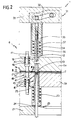
- equipment is indicated 1 for co-molding an insert 2 in a member 3 of synthetic plastics material; the insert 2 forms a plurality (for example two) of electrical circuits 4 ( Figure 7).
- the equipment 1 comprises essentially a pair of half-molds 5a and 5b, constituting an injection mold 6, provided with respective cavities 7a and 7b for molding the member 3 while the metal insert 2 is clamped in a predetermined position 8 inside the cavities 7 by at least one tubular die 11 and a blank holder 12.
- the equipment 1 is also provided with a punch 13 slidable within the blank holder 12 and cooperating with the die 11 to cut the insert 2 at a junction region 14 between the electrical circuits 4 so as to obtain respective cut metal parts 15, thereby separating the circuits 4 both mechanically and electrically.
- the blank holder 12, the die 11 and the punch 13 are axially slidable inside the half-molds 5 in respective fluid-tight through-seats 16 and 18 formed in the half-molds and opening into the respective cavities 7.
- the equipment 1 is in fact provided with two carriages 21 and 22 which effect the controlled axial displacement of the blank holder 12, of the die 11 and of the punch 13.
- the punch 13 and the blank holder 12 are supported by a support frame 31 of the respective half-mold 5a and are slidably mounted, the former within the latter, and fixed by a cam 32 to the second carriage 22 which is movable perpendicular to the direction of movement of the punch 13 and of the blank holder 12 and effects the controlled movement of these latter;
- the blank holder 12 includes an outer sleeve 34 in which a rod 35 which defines the punch 13 is slidable; a carrier sleeve 36 is connected to the cam 32 while a spring 37 is arranged between the outer sleeve 34 and the carrier sleeve 36 for providing resilient biasing for the blank holder 12.
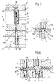
- the equipment 1 In order to hold the metal insert in the predetermined position 8, both before and during the injection of a fluid synthetic plastics material 33 into the cavities 7 when the blank holder 12, the die 11 and the punch 13 have been withdrawn by the carriages 21 and 22, the equipment 1 also includes a series of plungers 41 which act at restraining regions 42 of the metal insert 2 ( Figure 3) which differ from the junction regions 14.
- the plungers 41 are provided with respective springs 43, appropriately calibrated to transmit a predetermined force, and with tips 44 for coupling with respective centering holes 45 formed in the restraining regions 42 of the metal insert 2 ( Figure 7).
- the plungers 41 have a active surfaces 46 which are substantially larger than the corresponding contact surfaces 47 of the corresponding restraining regions 42 so that they project beyond the edges of these latter within the cavities 7 and, during the injection step and after the cavities 7 have been filled with fluid plastics material 33, are acted upon by the hydrostatic pressure which is such as to overcome the action of the springs 43 and thus enables the cavities 7 to be completely filled with the plastics material 33, even around the restraining regions 42.
- the process for the co-molding of the insert 2 in a member 3 of synthetic plastics material consists essentially of the following steps: a first step ( Figure 1) in which the insert 2 is arranged between the two half-molds 5 and, once the mold 6 is closed, the metal insert 2 is clamped in the predetermined position 8 both by the mutual cooperation of the blank holder 12 and the die 11 and by the plungers 41 which couple with the corresponding restraining regions 42; a second step ( Figure 2) in which the insert 2 is cut by the punch 13 with the formation of the cut metal parts 15; and a third step ( Figure 5) in which the punch 13, together with the blank holder 12 and the die 11, is moved away from the metal insert 2 which at this point is held in the predetermined position 8 by the plungers 41 alone.
Landscapes
- Engineering & Computer Science (AREA)
- Manufacturing & Machinery (AREA)
- Mechanical Engineering (AREA)
- Microelectronics & Electronic Packaging (AREA)
- Injection Moulding Of Plastics Or The Like (AREA)
- Moulds For Moulding Plastics Or The Like (AREA)
Applications Claiming Priority (2)
| Application Number | Priority Date | Filing Date | Title |
|---|---|---|---|
| ITTO920648 | 1992-07-28 | ||
| ITTO920648A IT1256901B (it) | 1992-07-28 | 1992-07-28 | Procedimento per il costampaggio di un inserto metallico realizzante una pluralita' di circuiti elettrici in un elemento in materiale plastico sintetico. |
Publications (2)
| Publication Number | Publication Date |
|---|---|
| EP0592768A1 EP0592768A1 (en) | 1994-04-20 |
| EP0592768B1 true EP0592768B1 (en) | 1997-11-12 |
Family
ID=11410645
Family Applications (1)
| Application Number | Title | Priority Date | Filing Date |
|---|---|---|---|
| EP93109956A Expired - Lifetime EP0592768B1 (en) | 1992-07-28 | 1993-06-22 | A process for co-molding a metal insert |
Country Status (3)
| Country | Link |
|---|---|
| EP (1) | EP0592768B1 (it) |
| DE (1) | DE69315172T2 (it) |
| IT (1) | IT1256901B (it) |
Cited By (1)
| Publication number | Priority date | Publication date | Assignee | Title |
|---|---|---|---|---|
| US10001661B1 (en) | 2014-03-06 | 2018-06-19 | Verily Life Sciences Llc | Body-mountable devices having an optical polarizer |
Families Citing this family (10)
| Publication number | Priority date | Publication date | Assignee | Title |
|---|---|---|---|---|
| DE19500790A1 (de) * | 1995-01-13 | 1996-07-18 | Bayer Ag | Verfahren und Vorrichtung zur Herstellung von Kunststoff/Metallverbundkörpern |
| FR2748414B1 (fr) * | 1996-05-10 | 1998-06-26 | Allibert Ind | Procede d'habillage d'une piece thermoplastique injectee par une feuille decoupee au cours du procede, moule pour la mise en oeuvre du procede et piece obtenue |
| FR2749795B1 (fr) * | 1996-06-12 | 1998-08-14 | James Juillard Ets | Moule pour la realisation d'un surmoulage, et procede de realisation d'une piece surmoulee avec decoupe d'insert integree |
| WO2005110703A1 (en) * | 2004-05-07 | 2005-11-24 | Decoma International | Injection forming and bonding process |
| US7572402B2 (en) * | 2004-08-17 | 2009-08-11 | Borgwarner Inc. | Method of overmolding circuit |
| US9782942B2 (en) | 2013-12-30 | 2017-10-10 | Verily Life Sciences Llc | Methods and apparatus for positioning a structure on a polymer layer |
| DE102014102024B4 (de) | 2014-02-18 | 2025-05-28 | Dr. Ing. H.C. F. Porsche Aktiengesellschaft | Verfahren zur Herstellung einer Öffnung in einem Faserverbundbauteil |
| JP2020049804A (ja) * | 2018-09-27 | 2020-04-02 | 日本電産株式会社 | インサート成形金型及びインサート成形品の製造方法 |
| CN116653214A (zh) * | 2023-04-20 | 2023-08-29 | 深圳市博硕科技股份有限公司 | 一种五金注塑混合模具结构 |
| CN118438604B (zh) * | 2023-10-30 | 2025-02-11 | 荣耀终端有限公司 | 嵌件注塑模具、嵌件注塑结构及其制备方法、摄像头模组 |
Family Cites Families (5)
| Publication number | Priority date | Publication date | Assignee | Title |
|---|---|---|---|---|
| JPH01262115A (ja) * | 1988-04-14 | 1989-10-19 | Seiko Epson Corp | Ic封止用射出成形金型 |
| US5203060A (en) * | 1989-05-22 | 1993-04-20 | Mraz James E | Apparatus for making insert molded circuitry |
| US4965933A (en) * | 1989-05-22 | 1990-10-30 | The Cherry Corporation | Process for making insert molded circuit |
| US5038468A (en) * | 1990-04-19 | 1991-08-13 | Illinois Tool Works Inc. | Method of insert molding with web placed in the mold |
| JPH04102338A (ja) * | 1990-08-22 | 1992-04-03 | Toshiba Corp | 樹脂封止型半導体装置の製造方法及び製造装置 |
-
1992
- 1992-07-28 IT ITTO920648A patent/IT1256901B/it active IP Right Grant
-
1993
- 1993-06-22 DE DE69315172T patent/DE69315172T2/de not_active Expired - Fee Related
- 1993-06-22 EP EP93109956A patent/EP0592768B1/en not_active Expired - Lifetime
Cited By (1)
| Publication number | Priority date | Publication date | Assignee | Title |
|---|---|---|---|---|
| US10001661B1 (en) | 2014-03-06 | 2018-06-19 | Verily Life Sciences Llc | Body-mountable devices having an optical polarizer |
Also Published As
| Publication number | Publication date |
|---|---|
| ITTO920648A0 (it) | 1992-07-28 |
| DE69315172T2 (de) | 1998-04-02 |
| DE69315172D1 (de) | 1997-12-18 |
| ITTO920648A1 (it) | 1994-01-28 |
| IT1256901B (it) | 1995-12-27 |
| EP0592768A1 (en) | 1994-04-20 |
Similar Documents
| Publication | Publication Date | Title |
|---|---|---|
| EP0592768B1 (en) | A process for co-molding a metal insert | |
| US3737272A (en) | Improved injection mold apparatus for the production of substantially cup-shaped and sleeve-shaped thermoplastic containers | |
| US3060509A (en) | Forming apparatus | |
| US5788905A (en) | Method for producing molded articles having inserts incorporated therein | |
| US5038468A (en) | Method of insert molding with web placed in the mold | |
| KR102370936B1 (ko) | 인서트 사출 성형장치 및 방법 | |
| EP0071343A1 (en) | Injection moulding method and apparatus | |
| US20200055220A1 (en) | Method and device for injection overmoulding | |
| US3685933A (en) | Apparatus for producing an assembly of interconnected and relatively movably displaceable molded parts | |
| US1161191A (en) | Process of mounting objects. | |
| US3192569A (en) | Apparatus for molding articles of plastic | |
| US4074413A (en) | Method and apparatus for manufacturing separable sliding clasp fasteners | |
| BR8706234A (pt) | Prensa aperfeicoada para a moldagem de artigos de material polimerico termoplastico,termoendurecivel e poliuretanico e seu processo de operacao | |
| JP7346521B2 (ja) | プラグを製造するための方法および射出成形金型 | |
| GB1599708A (en) | Composite articles | |
| US3763300A (en) | Method of encapsulating articles | |
| EP0115175A2 (en) | Elastomeric strip of encapsulated contacts | |
| US5940954A (en) | Apparatus for producing molded article and method therefor | |
| US3434201A (en) | Terminating and encapsulating devices in a single manufacturing operation | |
| US3590426A (en) | Apparatus for forming plastic articles | |
| US2306316A (en) | Die structure for injection molding machines | |
| US4176151A (en) | Method for manufacturing an article stopper device | |
| CN212352700U (zh) | 一种用于注塑模具零件加工的注塑嵌件固定装置 | |
| CN219705873U (zh) | 一种便于汽车模具脱模的注塑机 | |
| JP2620772B2 (ja) | インサート成形法並びにインサート成形機 |
Legal Events
| Date | Code | Title | Description |
|---|---|---|---|
| PUAI | Public reference made under article 153(3) epc to a published international application that has entered the european phase |
Free format text: ORIGINAL CODE: 0009012 |
|
| AK | Designated contracting states |
Kind code of ref document: A1 Designated state(s): DE ES FR GB MC SE |
|
| 17P | Request for examination filed |
Effective date: 19940929 |
|
| 17Q | First examination report despatched |
Effective date: 19960117 |
|
| GRAG | Despatch of communication of intention to grant |
Free format text: ORIGINAL CODE: EPIDOS AGRA |
|
| GRAH | Despatch of communication of intention to grant a patent |
Free format text: ORIGINAL CODE: EPIDOS IGRA |
|
| GRAH | Despatch of communication of intention to grant a patent |
Free format text: ORIGINAL CODE: EPIDOS IGRA |
|
| GRAA | (expected) grant |
Free format text: ORIGINAL CODE: 0009210 |
|
| AK | Designated contracting states |
Kind code of ref document: B1 Designated state(s): DE ES FR GB MC SE |
|
| PG25 | Lapsed in a contracting state [announced via postgrant information from national office to epo] |
Ref country code: ES Free format text: THE PATENT HAS BEEN ANNULLED BY A DECISION OF A NATIONAL AUTHORITY Effective date: 19971112 |
|
| REF | Corresponds to: |
Ref document number: 69315172 Country of ref document: DE Date of ref document: 19971218 |
|
| PG25 | Lapsed in a contracting state [announced via postgrant information from national office to epo] |
Ref country code: SE Free format text: LAPSE BECAUSE OF FAILURE TO SUBMIT A TRANSLATION OF THE DESCRIPTION OR TO PAY THE FEE WITHIN THE PRESCRIBED TIME-LIMIT Effective date: 19980212 |
|
| ET | Fr: translation filed | ||
| PGFP | Annual fee paid to national office [announced via postgrant information from national office to epo] |
Ref country code: GB Payment date: 19980615 Year of fee payment: 6 |
|
| PGFP | Annual fee paid to national office [announced via postgrant information from national office to epo] |
Ref country code: FR Payment date: 19980623 Year of fee payment: 6 |
|
| PGFP | Annual fee paid to national office [announced via postgrant information from national office to epo] |
Ref country code: DE Payment date: 19980624 Year of fee payment: 6 |
|
| PLBE | No opposition filed within time limit |
Free format text: ORIGINAL CODE: 0009261 |
|
| STAA | Information on the status of an ep patent application or granted ep patent |
Free format text: STATUS: NO OPPOSITION FILED WITHIN TIME LIMIT |
|
| 26N | No opposition filed | ||
| PG25 | Lapsed in a contracting state [announced via postgrant information from national office to epo] |
Ref country code: MC Free format text: LAPSE BECAUSE OF NON-PAYMENT OF DUE FEES Effective date: 19981231 |
|
| PG25 | Lapsed in a contracting state [announced via postgrant information from national office to epo] |
Ref country code: GB Free format text: LAPSE BECAUSE OF NON-PAYMENT OF DUE FEES Effective date: 19990622 |
|
| PG25 | Lapsed in a contracting state [announced via postgrant information from national office to epo] |
Ref country code: FR Free format text: THE PATENT HAS BEEN ANNULLED BY A DECISION OF A NATIONAL AUTHORITY Effective date: 19990630 |
|
| GBPC | Gb: european patent ceased through non-payment of renewal fee |
Effective date: 19990622 |
|
| PG25 | Lapsed in a contracting state [announced via postgrant information from national office to epo] |
Ref country code: DE Free format text: LAPSE BECAUSE OF NON-PAYMENT OF DUE FEES Effective date: 20000503 |
|
| REG | Reference to a national code |
Ref country code: FR Ref legal event code: ST |