EP0592771A1 - Procédé pour commander la température de l'eau chaude sanitaire dans une installation d'eau chaude sanitaire et dispositif de commande pour la mise en oeuvre de ce procédé - Google Patents
Procédé pour commander la température de l'eau chaude sanitaire dans une installation d'eau chaude sanitaire et dispositif de commande pour la mise en oeuvre de ce procédé Download PDFInfo
- Publication number
- EP0592771A1 EP0592771A1 EP93110813A EP93110813A EP0592771A1 EP 0592771 A1 EP0592771 A1 EP 0592771A1 EP 93110813 A EP93110813 A EP 93110813A EP 93110813 A EP93110813 A EP 93110813A EP 0592771 A1 EP0592771 A1 EP 0592771A1
- Authority
- EP
- European Patent Office
- Prior art keywords
- hot water
- value
- actual
- nominal
- water temperature
- Prior art date
- Legal status (The legal status is an assumption and is not a legal conclusion. Google has not performed a legal analysis and makes no representation as to the accuracy of the status listed.)
- Granted
Links
- XLYOFNOQVPJJNP-UHFFFAOYSA-N water Substances O XLYOFNOQVPJJNP-UHFFFAOYSA-N 0.000 title claims abstract description 97
- 238000000034 method Methods 0.000 title claims abstract description 37
- 238000010438 heat treatment Methods 0.000 claims abstract description 28
- 230000000694 effects Effects 0.000 claims description 18
- 238000012544 monitoring process Methods 0.000 claims 1
- 238000004891 communication Methods 0.000 description 7
- 238000010586 diagram Methods 0.000 description 6
- 230000001276 controlling effect Effects 0.000 description 4
- 238000001514 detection method Methods 0.000 description 2
- 239000013529 heat transfer fluid Substances 0.000 description 2
- 230000000737 periodic effect Effects 0.000 description 2
- 235000013290 Sagittaria latifolia Nutrition 0.000 description 1
- 230000005540 biological transmission Effects 0.000 description 1
- 235000015246 common arrowhead Nutrition 0.000 description 1
- 239000004020 conductor Substances 0.000 description 1
- 230000001419 dependent effect Effects 0.000 description 1
- 238000009413 insulation Methods 0.000 description 1
- 239000012528 membrane Substances 0.000 description 1
- 230000001105 regulatory effect Effects 0.000 description 1
Images

Classifications
-
- F—MECHANICAL ENGINEERING; LIGHTING; HEATING; WEAPONS; BLASTING
- F24—HEATING; RANGES; VENTILATING
- F24D—DOMESTIC- OR SPACE-HEATING SYSTEMS, e.g. CENTRAL HEATING SYSTEMS; DOMESTIC HOT-WATER SUPPLY SYSTEMS; ELEMENTS OR COMPONENTS THEREFOR
- F24D19/00—Details
- F24D19/10—Arrangement or mounting of control or safety devices
- F24D19/1006—Arrangement or mounting of control or safety devices for water heating systems
- F24D19/1066—Arrangement or mounting of control or safety devices for water heating systems for the combination of central heating and domestic hot water
-
- F—MECHANICAL ENGINEERING; LIGHTING; HEATING; WEAPONS; BLASTING
- F24—HEATING; RANGES; VENTILATING
- F24H—FLUID HEATERS, e.g. WATER OR AIR HEATERS, HAVING HEAT-GENERATING MEANS, e.g. HEAT PUMPS, IN GENERAL
- F24H15/00—Control of fluid heaters
- F24H15/10—Control of fluid heaters characterised by the purpose of the control
- F24H15/174—Supplying heated water with desired temperature or desired range of temperature
- F24H15/175—Supplying heated water with desired temperature or desired range of temperature where the difference between the measured temperature and a set temperature is kept under a predetermined value
-
- F—MECHANICAL ENGINEERING; LIGHTING; HEATING; WEAPONS; BLASTING
- F24—HEATING; RANGES; VENTILATING
- F24H—FLUID HEATERS, e.g. WATER OR AIR HEATERS, HAVING HEAT-GENERATING MEANS, e.g. HEAT PUMPS, IN GENERAL
- F24H15/00—Control of fluid heaters
- F24H15/20—Control of fluid heaters characterised by control inputs
- F24H15/269—Time, e.g. hour or date
-
- F—MECHANICAL ENGINEERING; LIGHTING; HEATING; WEAPONS; BLASTING
- F24—HEATING; RANGES; VENTILATING
- F24H—FLUID HEATERS, e.g. WATER OR AIR HEATERS, HAVING HEAT-GENERATING MEANS, e.g. HEAT PUMPS, IN GENERAL
- F24H15/00—Control of fluid heaters
- F24H15/30—Control of fluid heaters characterised by control outputs; characterised by the components to be controlled
- F24H15/335—Control of pumps, e.g. on-off control
-
- F—MECHANICAL ENGINEERING; LIGHTING; HEATING; WEAPONS; BLASTING
- F24—HEATING; RANGES; VENTILATING
- F24H—FLUID HEATERS, e.g. WATER OR AIR HEATERS, HAVING HEAT-GENERATING MEANS, e.g. HEAT PUMPS, IN GENERAL
- F24H15/00—Control of fluid heaters
- F24H15/30—Control of fluid heaters characterised by control outputs; characterised by the components to be controlled
- F24H15/355—Control of heat-generating means in heaters
- F24H15/36—Control of heat-generating means in heaters of burners
-
- F—MECHANICAL ENGINEERING; LIGHTING; HEATING; WEAPONS; BLASTING
- F24—HEATING; RANGES; VENTILATING
- F24H—FLUID HEATERS, e.g. WATER OR AIR HEATERS, HAVING HEAT-GENERATING MEANS, e.g. HEAT PUMPS, IN GENERAL
- F24H15/00—Control of fluid heaters
- F24H15/30—Control of fluid heaters characterised by control outputs; characterised by the components to be controlled
- F24H15/355—Control of heat-generating means in heaters
- F24H15/37—Control of heat-generating means in heaters of electric heaters
-
- F—MECHANICAL ENGINEERING; LIGHTING; HEATING; WEAPONS; BLASTING
- F24—HEATING; RANGES; VENTILATING
- F24H—FLUID HEATERS, e.g. WATER OR AIR HEATERS, HAVING HEAT-GENERATING MEANS, e.g. HEAT PUMPS, IN GENERAL
- F24H15/00—Control of fluid heaters
- F24H15/40—Control of fluid heaters characterised by the type of controllers
- F24H15/414—Control of fluid heaters characterised by the type of controllers using electronic processing, e.g. computer-based
- F24H15/421—Control of fluid heaters characterised by the type of controllers using electronic processing, e.g. computer-based using pre-stored data
- F24H15/429—Control of fluid heaters characterised by the type of controllers using electronic processing, e.g. computer-based using pre-stored data for selecting operation modes
-
- G—PHYSICS
- G05—CONTROLLING; REGULATING
- G05D—SYSTEMS FOR CONTROLLING OR REGULATING NON-ELECTRIC VARIABLES
- G05D23/00—Control of temperature
- G05D23/19—Control of temperature characterised by the use of electric means
- G05D23/1902—Control of temperature characterised by the use of electric means characterised by the use of a variable reference value
Definitions
- the invention relates to a method for controlling the hot water temperature in a hot water system and to a control device for carrying out the method according to the preambles of claims 1 and 10.
- Such control devices are advantageously used together with a hot water controller to control or regulate the hot water temperature, wherein the hot water controller can also be integrated in a heating circuit controller.
- a control device of this type is known (Landis & Gyr, "SIGMAGYR RVP DIGITAL", description CE1P2440 D, July 1989, chapter 8.4), which has a recharge button and with which, after a manual actuation of the recharge button, the hot water is independent of a valid operating mode or can be heated for two and a half hours from the status of a running heating program. Without the action of the reload button, depending on the operating mode or the state of the heating program, the hot water is either heated to an adjustable setpoint, for example set to 60 ° C, with the aid of a heat exchanger, or the heat exchanger is switched off, after which the hot water changes depending on Insulation and hot water supply cools down.
- an adjustable setpoint for example set to 60 ° C
- the invention has for its object to provide a method for controlling the domestic hot water temperature, which makes hot domestic water available at all times, but avoids keeping the domestic hot water unnecessarily, and to provide a control device which operates according to the control method.
- a heating system in FIG. 1, 1 means a boiler which can be heated by a burner 2.
- a heat transfer fluid flows under the action of at least one circulation pump 3 through a heating flow line 4 to a heat dispenser 5, for example a radiator, and from the heat dispenser 5 through a heating return line 6 back to the boiler 1.
- the heating system has a weather sensor 7, a room unit 8, one Boiler temperature sensor 9 and a control device 10.
- the control device 10 has a heating circuit controller and is connected to the room device 8, the circulation pump 3, the burner 2, the boiler temperature sensor 9 and the weather sensor 7 by electrical conductors.
- a hot water system is integrated in the heating system, which has a hot water tank 11 for the hot water and a hot water controller for regulating the hot water temperature.
- the process water can be heated by a further heat source 12 and / or an electric heater 13.
- the heat transfer fluid flows under the action of a charging pump 14 through a charging flow line 15 branching off from the heating flow line 4, through the further heat donor 12 and through a charging return line 16 connected to the heating return line 6.
- the hot water controller is arranged in the control unit 10 and functionally connected to the heating circuit controller if necessary.
- the hot water temperature can be measured by means of a hot water temperature sensor 17 connected to the hot water controller.
- the process water controller acts on the charge pump 14 and / or on the electric heater 13 and possibly also on the burner 2 by means of control signals.
- devices such as the charge pump 14 and / or the electric heater 13 and / or the burner 2, which can be influenced by the control signals, are also generally referred to as heating means.
- the domestic hot water system can be operated in at least one nominal operating mode and in one economy mode, with a nominal value T nominal in the nominal operating mode and another nominal value T Spar in the economy mode being decisive for the desired domestic water temperature.
- a valid operating mode is selected in a known manner either manually via a mode switch or automatically from a heating program.
- the control device 10 has a control device, which also then reloads - that is, additional heating - the Domestic water enables if the economy mode is selected for the domestic water system.
- control device has a reload button 18 arranged on the control device 10, which is not required in an embodiment of the control device according to the invention.
- FIG. 2 shows the basic structure of the control device according to the invention using a data flow diagram.
- a circle means an activity, a rectangle an adjacent system (terminator) and an arrow a communication channel (channel) for the transmission of data and / or events, the arrow head pointing in the essential data flow direction.
- a data store (pool) which is generally available for several activities, is represented by two parallel lines of the same length. Furthermore, for example, an arrangement of two activities connected by a communication channel is equivalent to a single activity which fulfills all the tasks of the two activities.
- Activities are implemented as an electronic circuit and / or as a process, program piece or routine.
- the actual value T Ist and the valid setpoint T Soll of the hot water temperature are stored in a first pool 19 and in a second pool 20.
- An activity 21 is connected to the first pool 19 via a first communication channel 22 and to the second pool 20 via a second communication channel 23.
- An adjacent system 24 is an input part of the domestic water controller, which is connected to the first pool 19 via a third communication channel 25 and to the second pool 20 via a fourth communication channel 26. If necessary, a fifth communication channel 27 leads to activity 21 for an event e.
- the hot water controller forms, based on the difference between the target value T target available in the second pool 20 and the actual value T actual stored in the first pool 19, at least one desired control signal for controlling the hot water temperature in a known manner.
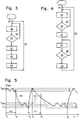
- FIG. 3 shows a flow chart in which a beginning 28 is followed by an endless loop 29 which, as loop steps, has an inner loop 30, followed by a first action block 31, a second action block 32 and a third action block 33.
- the inner loop 30 has a fourth action block 34 and a loop condition 35.
- FIG. 4 differs from the flowchart of FIG. 3 only in that after the first action block 31 instead of the second action block 32 (FIG. 3) there follows a further loop 36 which has a further action block 37 and has a further loop condition 38.
- Fig. 5 39 shows a basic, not true-to-scale course of the domestic water temperature T BW depending on the time t.
- the hot water system operates in the nominal operating mode, the target value T of the nominal current for the hot water controller setpoint T set; the hot water temperature T BW runs within limits which are determined by a switching difference b.
- the hot water system is switched to the economy mode, whereby its setpoint T Spar is set as the applicable setpoint T setpoint for the hot water controller.
- the hot water controller strives for the setpoint with a switching difference a T save .
- the switching difference a and the switching difference b are matched to the desired properties of the hot water controller and are, for example, each about 4 K.
- the nominal values T nominal and T saving are 60 ° C and 40 ° C, no hot water is drawn and the hot water tank 11 is thermally insulated in the usual way, it can take several days until the hot water reaches the nominal value T. Spar has cooled; when hot water is drawn, the hot water cools down correspondingly faster.
- the process water temperature is monitored by activity 21 (FIG. 2) by periodically comparing the actual value T actual measured by the process water temperature sensor 17 and available in the first pool 19 with the threshold value T T.
- the activity 21 introduces the nominal value T nominal in the nominal operating mode up to a predetermined event, regardless of the operating mode in question, as the valid nominal value T nominal , by the nominal value T nominal in the second pool 20 is copied.
- the applicable setpoint T Soll is used again in accordance with the applicable operating mode; in the economy mode, the activity copies the target value T economy into the second pool 20.
- the predetermined event is advantageously an adjustment of the actual value T actual of the hot water temperature to the target value T nominal which is decisive in the nominal operating mode. 5 is an example at a fourth time t4 evident.
- the predetermined event which is visible in the course 42 can advantageously also be the reaching of a fifth point in time t5 which, after a predetermined time period 41, follows the falling below the threshold value T T in the third point in time t3.
- the predetermined time period 41 is advantageously the maximum permitted switch-on time of the heating means.
- the time period 41 is advantageously about two and a half hours; a much longer period of time could have a correspondingly greater impact on the functioning of the heating system.
- the time period 41 and also the adjustment of the actual value T actual to the target value T nominal are monitored and the heating medium is switched off when the first of the two monitored events occurs.
- the threshold value T T is undershot again, whereupon the service water is again heated up strongly.
- the hot water temperature reaches the nominal value T Nom in the example just before a seventh time t7.
- the activity advantageously carries out method steps according to the flow diagram shown in FIG. 3.
- the domestic water temperature is monitored in the inner loop 30 by detecting the actual value T Ist in the fourth action block 34 and comparing the actual value T Ist with the threshold value T T in the loop condition 35.
- the inner loop 30 essentially becomes periodically run through what can be achieved with the help of event e (FIG. 2), if this is periodic and triggers the detection of the actual value T Ist in the fourth action block 34.
- the inner loop 30 is ended when the actual value T Ist is less than the threshold value T T.
- the applicable target value T Soll is set equal to the target value T Nom applicable in the nominal operating mode, and the predetermined event is awaited in the action block 32 in a known manner.
- the valid target value T target is set again in the third action block 33 according to the valid operating mode.
- the activity 21 advantageously executes the further loop 36 (FIG. 4) after the first action block 31 if the predetermined event is the adjustment of the actual value T actual to the nominal value T nominal which is decisive in the nominal operating mode.
- the process water temperature is monitored in the further loop 36, in that the actual value T actual is recorded in the action block 36 and the actual value T actual is compared with the target value T nominal in the loop condition 38.
- the further loop 36 is run through periodically, which can be achieved with the help of event e (FIG. 2) if it is periodic and triggers the detection of the actual value T actual in action block 36.
- the further loop 36 is ended when the actual value T actual reaches the target value T target .
- a limit value is introduced which is below the nominal value T nominal applicable in the nominal operating mode, and the hot water temperature is also changed in the economy mode supervised.
- the limit value is the lower threshold of the switching difference a of the setpoint T Spar valid in the economy mode or the limit value is the threshold value T T.
- the setpoint T saving and also the threshold value T T can advantageously be changed on the device.
- the domestic water controller uses the setpoint T Spar in the economy mode, which is advantageously at the desired bath water temperature, that is to say in the range from 35 to 40 ° C.
- This variant is particularly advantageous in the case of larger domestic water storage tanks 11 which require a relatively long heating-up time. If the domestic water system operates in economy mode for several days, there is only a small loss of energy due to the relatively small temperature difference between the domestic water and its surroundings. If the domestic hot water is used repeatedly in the economy mode, the domestic water does not have more than the temperature of the setpoint T Spar .
- the domestic water system works in the same way as a heating system, which also has two different setpoints.
- the hot water temperature is monitored by activity 21 in the economy mode and, if the actual value T actual falls below the threshold value T T , the hot water is heated until the predetermined event occurs.
- the threshold value T T is advantageously at the desired bath water temperature, that is to say approximately in the range from 35 to 40 ° C.
- the further target value T Spar is not introduced or is arranged lower than the threshold value T T.
- the heating medium is advantageously switched on less often in the economy mode. If the threshold value T T is reached, the process water is heated up, so that in a subsequent draw, warmer process water is available compared to the first variant.
- a third variant of the method is a combination of the first and the second variant: the domestic water controller works in the economy mode according to the further setpoint T Spar , which is advantageously around 40 ° C.
- the hot water temperature is monitored by activity 21 and, when the actual value T Ist falls below the threshold value T T , the hot water is heated until the predetermined event occurs.
- the threshold value T T lies by a certain amount c below the lower limit of the switching difference a which is valid for the further target value T Spar .
- the amount c is advantageously about half the switching difference a.
Landscapes
- Engineering & Computer Science (AREA)
- Physics & Mathematics (AREA)
- Mechanical Engineering (AREA)
- General Engineering & Computer Science (AREA)
- Thermal Sciences (AREA)
- Chemical & Material Sciences (AREA)
- Combustion & Propulsion (AREA)
- Computer Hardware Design (AREA)
- Automation & Control Theory (AREA)
- General Physics & Mathematics (AREA)
- Control Of Temperature (AREA)
- Heat-Pump Type And Storage Water Heaters (AREA)
- Feedback Control In General (AREA)
Applications Claiming Priority (2)
| Application Number | Priority Date | Filing Date | Title |
|---|---|---|---|
| CH317992 | 1992-10-12 | ||
| CH3179/92 | 1992-10-12 |
Publications (2)
| Publication Number | Publication Date |
|---|---|
| EP0592771A1 true EP0592771A1 (fr) | 1994-04-20 |
| EP0592771B1 EP0592771B1 (fr) | 1997-03-05 |
Family
ID=4250337
Family Applications (1)
| Application Number | Title | Priority Date | Filing Date |
|---|---|---|---|
| EP93110813A Expired - Lifetime EP0592771B1 (fr) | 1992-10-12 | 1993-07-07 | Procédé pour commander la température de l'eau chaude sanitaire dans une installation d'eau chaude sanitaire et dispositif de commande pour la mise en oeuvre de ce procédé |
Country Status (4)
| Country | Link |
|---|---|
| EP (1) | EP0592771B1 (fr) |
| AT (1) | ATE149664T1 (fr) |
| DE (1) | DE59305588D1 (fr) |
| DK (1) | DK0592771T3 (fr) |
Cited By (4)
| Publication number | Priority date | Publication date | Assignee | Title |
|---|---|---|---|---|
| GB2363189A (en) * | 2000-06-08 | 2001-12-12 | Gasforce Ltd | Controller for water-heating system |
| FR2811198A1 (fr) * | 2000-07-04 | 2002-01-11 | Patrick Avrillas | Dispositif de protection des vegetaux contre le gel |
| EP2397927A1 (fr) * | 2010-06-17 | 2011-12-21 | STIEBEL ELTRON GmbH & Co. KG | Procédé de commande de température d'un accumulateur d'eau chaude et accumulateur d'eau chaude |
| EP2570739A2 (fr) * | 2011-09-16 | 2013-03-20 | Robert Bosch Gmbh | Procédé et dispositif destinés à la préparation d'eau chaude |
Citations (2)
| Publication number | Priority date | Publication date | Assignee | Title |
|---|---|---|---|---|
| EP0121164A2 (fr) * | 1983-03-15 | 1984-10-10 | Friedrich Müller | Appareil pour régler et/ou pour surveiller l'amenée de chaleur à un chauffe-eau et/ou à un générateur de chaleur ambiante |
| DE3538934A1 (de) * | 1984-11-16 | 1986-05-28 | Joh. Vaillant Gmbh U. Co, 5630 Remscheid | Verfahren zur absenkung eines temperaturniveaus |
-
1993
- 1993-07-07 DK DK93110813.8T patent/DK0592771T3/da active
- 1993-07-07 EP EP93110813A patent/EP0592771B1/fr not_active Expired - Lifetime
- 1993-07-07 DE DE59305588T patent/DE59305588D1/de not_active Expired - Fee Related
- 1993-07-07 AT AT93110813T patent/ATE149664T1/de not_active IP Right Cessation
Patent Citations (2)
| Publication number | Priority date | Publication date | Assignee | Title |
|---|---|---|---|---|
| EP0121164A2 (fr) * | 1983-03-15 | 1984-10-10 | Friedrich Müller | Appareil pour régler et/ou pour surveiller l'amenée de chaleur à un chauffe-eau et/ou à un générateur de chaleur ambiante |
| DE3538934A1 (de) * | 1984-11-16 | 1986-05-28 | Joh. Vaillant Gmbh U. Co, 5630 Remscheid | Verfahren zur absenkung eines temperaturniveaus |
Cited By (4)
| Publication number | Priority date | Publication date | Assignee | Title |
|---|---|---|---|---|
| GB2363189A (en) * | 2000-06-08 | 2001-12-12 | Gasforce Ltd | Controller for water-heating system |
| FR2811198A1 (fr) * | 2000-07-04 | 2002-01-11 | Patrick Avrillas | Dispositif de protection des vegetaux contre le gel |
| EP2397927A1 (fr) * | 2010-06-17 | 2011-12-21 | STIEBEL ELTRON GmbH & Co. KG | Procédé de commande de température d'un accumulateur d'eau chaude et accumulateur d'eau chaude |
| EP2570739A2 (fr) * | 2011-09-16 | 2013-03-20 | Robert Bosch Gmbh | Procédé et dispositif destinés à la préparation d'eau chaude |
Also Published As
| Publication number | Publication date |
|---|---|
| DK0592771T3 (da) | 1997-08-04 |
| DE59305588D1 (de) | 1997-04-10 |
| ATE149664T1 (de) | 1997-03-15 |
| EP0592771B1 (fr) | 1997-03-05 |
Similar Documents
| Publication | Publication Date | Title |
|---|---|---|
| DE2933606C2 (de) | Heißwasserbereiter | |
| DE2843929B2 (de) | Anordnung zur Steuerung der Raumtemperatur | |
| EP0592771B1 (fr) | Procédé pour commander la température de l'eau chaude sanitaire dans une installation d'eau chaude sanitaire et dispositif de commande pour la mise en oeuvre de ce procédé | |
| EP2667104A2 (fr) | Installation et procédé de chauffage d'eau potable | |
| EP2604946A2 (fr) | Accumulateur d'eau chaude avec réglage de la température de préparation sur la base d'informations de débit | |
| DE3727442C2 (fr) | ||
| DE3541257A1 (de) | Regelvorrichtung fuer zentralheizungsanlage mit warmwasservorrat | |
| DE102021120396A1 (de) | Leitungsanordnung mit dezentraler Trinkwassererwärmung und Verfahren zum Betrieb einer Leitungsanordnung | |
| DE3030565A1 (de) | Heizkessel fuer heizungsanlagen | |
| AT397425B (de) | Steuerverfahren für eine heizungsanlage | |
| DE102010056301B4 (de) | Verfahren zur automatischen Optimierung einer Aufheizphase eines Heizsystems sowie ein Heizsystem | |
| DE69105742T2 (de) | Zentralheizungsanlage. | |
| DE2307109A1 (de) | Heizgeraet fuer brauch- und heizwasser | |
| DE3138701C2 (de) | Einrichtung zur Vorgabe des Sollwertes der Raumtemperatur eines Heizungssystems | |
| DE3315881C2 (de) | Betriebsverfahren für eine Heizungsumwälzpumpe | |
| EP3303935B1 (fr) | Dispositif et procédé de commande d'une installation de chauffage et/ou de climatisation | |
| DE3923030A1 (de) | Steuerung eines umlaufwasserheizers | |
| EP0384959B1 (fr) | Régulateur pour un brûleur non modulant | |
| DE4138858A1 (de) | Warmwasser-versorgungssystem | |
| DE2631476A1 (de) | Verfahren und einrichtung zur beeinflussung der temperatur mindestens eines gebaeuderaumes | |
| DE10057942A1 (de) | Verfahren und Vorrichtung zur Steuerung einer Zentralheizungsanlage | |
| EP0351716B1 (fr) | Commande d'un appareil de production d'eau chaude en circulation | |
| DE10044734A1 (de) | Anordnung zur Anpassung eines Heizgerätes an den tatsächlichen Wärmebedarf | |
| EP0711960A1 (fr) | Procédé et dispositif pour chauffer de l'eau sanitaire | |
| EP0530727B2 (fr) | Appareil de chauffage à accumulation |
Legal Events
| Date | Code | Title | Description |
|---|---|---|---|
| PUAI | Public reference made under article 153(3) epc to a published international application that has entered the european phase |
Free format text: ORIGINAL CODE: 0009012 |
|
| AK | Designated contracting states |
Kind code of ref document: A1 Designated state(s): AT CH DE DK FR LI SE |
|
| 17P | Request for examination filed |
Effective date: 19940628 |
|
| RAP1 | Party data changed (applicant data changed or rights of an application transferred) |
Owner name: LANDIS & GYR TECHNOLOGY INNOVATION AG |
|
| 17Q | First examination report despatched |
Effective date: 19951009 |
|
| GRAG | Despatch of communication of intention to grant |
Free format text: ORIGINAL CODE: EPIDOS AGRA |
|
| GRAH | Despatch of communication of intention to grant a patent |
Free format text: ORIGINAL CODE: EPIDOS IGRA |
|
| GRAH | Despatch of communication of intention to grant a patent |
Free format text: ORIGINAL CODE: EPIDOS IGRA |
|
| GRAA | (expected) grant |
Free format text: ORIGINAL CODE: 0009210 |
|
| AK | Designated contracting states |
Kind code of ref document: B1 Designated state(s): AT CH DE DK FR LI SE |
|
| REF | Corresponds to: |
Ref document number: 149664 Country of ref document: AT Date of ref document: 19970315 Kind code of ref document: T |
|
| REG | Reference to a national code |
Ref country code: CH Ref legal event code: EP |
|
| REF | Corresponds to: |
Ref document number: 59305588 Country of ref document: DE Date of ref document: 19970410 |
|
| ET | Fr: translation filed | ||
| REG | Reference to a national code |
Ref country code: DK Ref legal event code: T3 |
|
| PLBE | No opposition filed within time limit |
Free format text: ORIGINAL CODE: 0009261 |
|
| STAA | Information on the status of an ep patent application or granted ep patent |
Free format text: STATUS: NO OPPOSITION FILED WITHIN TIME LIMIT |
|
| 26N | No opposition filed | ||
| REG | Reference to a national code |
Ref country code: CH Ref legal event code: PFA Free format text: LANDIS & GYR TECHNOLOGY INNOVATION AG TRANSFER- SIEMENS BUILDING TECHNOLOGIES AG C-IPR |
|
| PGFP | Annual fee paid to national office [announced via postgrant information from national office to epo] |
Ref country code: AT Payment date: 20060614 Year of fee payment: 14 |
|
| PGFP | Annual fee paid to national office [announced via postgrant information from national office to epo] |
Ref country code: FR Payment date: 20060727 Year of fee payment: 14 |
|
| PGFP | Annual fee paid to national office [announced via postgrant information from national office to epo] |
Ref country code: DE Payment date: 20060918 Year of fee payment: 14 |
|
| PGFP | Annual fee paid to national office [announced via postgrant information from national office to epo] |
Ref country code: CH Payment date: 20061012 Year of fee payment: 14 |
|
| REG | Reference to a national code |
Ref country code: CH Ref legal event code: PL |
|
| EUG | Se: european patent has lapsed | ||
| REG | Reference to a national code |
Ref country code: DK Ref legal event code: EBP |
|
| PG25 | Lapsed in a contracting state [announced via postgrant information from national office to epo] |
Ref country code: SE Free format text: LAPSE BECAUSE OF NON-PAYMENT OF DUE FEES Effective date: 20070708 Ref country code: LI Free format text: LAPSE BECAUSE OF NON-PAYMENT OF DUE FEES Effective date: 20070731 Ref country code: DE Free format text: LAPSE BECAUSE OF NON-PAYMENT OF DUE FEES Effective date: 20080201 Ref country code: CH Free format text: LAPSE BECAUSE OF NON-PAYMENT OF DUE FEES Effective date: 20070731 |
|
| PGFP | Annual fee paid to national office [announced via postgrant information from national office to epo] |
Ref country code: DK Payment date: 20060710 Year of fee payment: 14 |
|
| REG | Reference to a national code |
Ref country code: FR Ref legal event code: ST Effective date: 20080331 |
|
| PG25 | Lapsed in a contracting state [announced via postgrant information from national office to epo] |
Ref country code: AT Free format text: LAPSE BECAUSE OF NON-PAYMENT OF DUE FEES Effective date: 20070707 |
|
| PGFP | Annual fee paid to national office [announced via postgrant information from national office to epo] |
Ref country code: SE Payment date: 20060707 Year of fee payment: 14 |
|
| PG25 | Lapsed in a contracting state [announced via postgrant information from national office to epo] |
Ref country code: DK Free format text: LAPSE BECAUSE OF NON-PAYMENT OF DUE FEES Effective date: 20070731 |
|
| PG25 | Lapsed in a contracting state [announced via postgrant information from national office to epo] |
Ref country code: FR Free format text: LAPSE BECAUSE OF NON-PAYMENT OF DUE FEES Effective date: 20070731 |