EP0592777A1 - Ferrure de charnière pour battants de fenêtre, de portes ou similaires - Google Patents
Ferrure de charnière pour battants de fenêtre, de portes ou similaires Download PDFInfo
- Publication number
- EP0592777A1 EP0592777A1 EP93111712A EP93111712A EP0592777A1 EP 0592777 A1 EP0592777 A1 EP 0592777A1 EP 93111712 A EP93111712 A EP 93111712A EP 93111712 A EP93111712 A EP 93111712A EP 0592777 A1 EP0592777 A1 EP 0592777A1
- Authority
- EP
- European Patent Office
- Prior art keywords
- hinge
- stop
- coupling
- wing
- actuator
- Prior art date
- Legal status (The legal status is an assumption and is not a legal conclusion. Google has not performed a legal analysis and makes no representation as to the accuracy of the status listed.)
- Granted
Links
- 230000008878 coupling Effects 0.000 claims abstract description 58
- 238000010168 coupling process Methods 0.000 claims abstract description 58
- 238000005859 coupling reaction Methods 0.000 claims abstract description 58
- 230000000295 complement effect Effects 0.000 claims abstract description 4
- 235000001674 Agaricus brunnescens Nutrition 0.000 claims description 5
- 238000004080 punching Methods 0.000 claims description 4
- 210000002105 tongue Anatomy 0.000 claims description 4
- 238000007373 indentation Methods 0.000 claims description 3
- 238000003780 insertion Methods 0.000 claims description 3
- 230000037431 insertion Effects 0.000 claims description 3
- 238000000465 moulding Methods 0.000 abstract description 8
- 210000003128 head Anatomy 0.000 description 8
- 238000013461 design Methods 0.000 description 3
- 238000009434 installation Methods 0.000 description 3
- 230000001154 acute effect Effects 0.000 description 1
- 230000015572 biosynthetic process Effects 0.000 description 1
- 238000011161 development Methods 0.000 description 1
- 238000006073 displacement reaction Methods 0.000 description 1
- 238000011900 installation process Methods 0.000 description 1
- 238000000034 method Methods 0.000 description 1
- 230000006641 stabilisation Effects 0.000 description 1
- 238000011105 stabilization Methods 0.000 description 1
- 238000012549 training Methods 0.000 description 1
Images


Classifications
-
- E—FIXED CONSTRUCTIONS
- E05—LOCKS; KEYS; WINDOW OR DOOR FITTINGS; SAFES
- E05D—HINGES OR SUSPENSION DEVICES FOR DOORS, WINDOWS OR WINGS
- E05D15/00—Suspension arrangements for wings
- E05D15/48—Suspension arrangements for wings allowing alternative movements
- E05D15/52—Suspension arrangements for wings allowing alternative movements for opening about a vertical as well as a horizontal axis
- E05D15/5205—Suspension arrangements for wings allowing alternative movements for opening about a vertical as well as a horizontal axis with horizontally-extending checks
-
- E—FIXED CONSTRUCTIONS
- E05—LOCKS; KEYS; WINDOW OR DOOR FITTINGS; SAFES
- E05D—HINGES OR SUSPENSION DEVICES FOR DOORS, WINDOWS OR WINGS
- E05D5/00—Construction of single parts, e.g. the parts for attachment
- E05D5/02—Parts for attachment, e.g. flaps
- E05D5/0215—Parts for attachment, e.g. flaps for attachment to profile members or the like
- E05D5/0223—Parts for attachment, e.g. flaps for attachment to profile members or the like with parts, e.g. screws, extending through the profile wall or engaging profile grooves
- E05D5/0238—Parts for attachment, e.g. flaps for attachment to profile members or the like with parts, e.g. screws, extending through the profile wall or engaging profile grooves with parts engaging profile grooves
-
- E—FIXED CONSTRUCTIONS
- E05—LOCKS; KEYS; WINDOW OR DOOR FITTINGS; SAFES
- E05D—HINGES OR SUSPENSION DEVICES FOR DOORS, WINDOWS OR WINGS
- E05D7/00—Hinges or pivots of special construction
- E05D7/02—Hinges or pivots of special construction for use on the right-hand as well as the left-hand side; Convertible right-hand or left-hand hinges
-
- E—FIXED CONSTRUCTIONS
- E05—LOCKS; KEYS; WINDOW OR DOOR FITTINGS; SAFES
- E05Y—INDEXING SCHEME ASSOCIATED WITH SUBCLASSES E05D AND E05F, RELATING TO CONSTRUCTION ELEMENTS, ELECTRIC CONTROL, POWER SUPPLY, POWER SIGNAL OR TRANSMISSION, USER INTERFACES, MOUNTING OR COUPLING, DETAILS, ACCESSORIES, AUXILIARY OPERATIONS NOT OTHERWISE PROVIDED FOR, APPLICATION THEREOF
- E05Y2800/00—Details, accessories and auxiliary operations not otherwise provided for
- E05Y2800/37—Length, width or depth adjustment
-
- E—FIXED CONSTRUCTIONS
- E05—LOCKS; KEYS; WINDOW OR DOOR FITTINGS; SAFES
- E05Y—INDEXING SCHEME ASSOCIATED WITH SUBCLASSES E05D AND E05F, RELATING TO CONSTRUCTION ELEMENTS, ELECTRIC CONTROL, POWER SUPPLY, POWER SIGNAL OR TRANSMISSION, USER INTERFACES, MOUNTING OR COUPLING, DETAILS, ACCESSORIES, AUXILIARY OPERATIONS NOT OTHERWISE PROVIDED FOR, APPLICATION THEREOF
- E05Y2900/00—Application of doors, windows, wings or fittings thereof
- E05Y2900/10—Application of doors, windows, wings or fittings thereof for buildings or parts thereof
- E05Y2900/13—Type of wing
- E05Y2900/148—Windows
Definitions
- the invention relates to a hinge fitting for the sash of windows, doors or the like.
- the attachment consists of a fitting which is positively in an undercut, for example in cross-section C or dovetail-shaped Profile groove of a wing leg insertable and position-adjustable in its longitudinal direction on an actuator in the wing, for example is supported by screws, a fixed stop, with a shaped and open window-like cutout being provided in the fitting, in which the wing-side fixed stop engages in a relatively displaceable manner in the longitudinal direction, the cutout on the one hand and the stop on its longitudinal walls on the other in certain areas has interrupted guide strips which can be brought into engagement with one another transversely to the direction of action of the actuator and can be fixed in their mutual engagement position by the actuator, and wherein the actuator is designed as a screw which can be screwed into the cutout through the end wall of the shaped piece.
- a hinge fitting of this type is part of the prior art, for example, by DE-U-76 36 855 and has been used there in particular on opening devices for the sash of tilt-and-turn windows, doors or the like, which have a fixed frame in the region of the pivot axis of the
- the wing is only equipped with a pivoting arm that can pivot and slide on the wing and is equipped with an additional arm on the one hand on the raising arm and on the other hand only pivotally mounted on the wing, with the sliding guide for the raising arm and the storage for the additional arm being on the shaped piece designed as a profile rail.
- a hinge fitting similar to DE-U-76 36 855 for opening devices of tilt-and-turn windows, doors or the like is also known from DE-U 77 21 479.
- the aim of the invention is to provide a hinge fitting of the type specified at the outset which does not have the disadvantages of the known hinge fittings dealt with above. Therefore, the invention has for its object to provide a hinge fitting that not only ensures a simple and problem-free attachment to the wing, but also allows the adjustment to the right and left stop without further ado, thus avoiding loosening and tightening of screw connections.
- the hinge strap can be connected to the fitting exclusively by a positive plug-in coupling, the first coupling half of which is formed by recesses and projections provided on the underside of the fitting, while the second coupling half consists of one of the hinge strap normal to the hinge axis protruding tab, which in the direction parallel to the hinge axis has a complementary to the recesses and projections of the molding, and that both coupling halves of the plug-in coupling are designed symmetrically to their longitudinal center.
- hinge fitting All of the functional parts essential for the formation of the hinge fitting, i.e. the hinge, the fitting and the stop, can be easily inserted in the longitudinal direction into the undercut profile groove of the wing limb in question, and are then simply tightened fixed by stop screws in this profile groove on the wing leg. In this installation process, it is then only necessary to ensure that the hinge is connected to the fitting via the positive plug-in coupling in accordance with the intended stop direction.
- the flap forming the second coupling half is arranged on a plane of symmetry crossing the hinge axis of the hinge and the profile extends uniformly over its entire thickness.
- both coupling halves of the plug-in coupling extends at least over the maximum profile depth of the undercut profile groove in the wing leg, while their maximum mutual engagement width is matched to the clear opening width of the undercut profile groove.
- the coupling half of the plug-in coupling provided on the hinge can in this embodiment also directly enter into an active connection with the wing leg by not only supporting it on the bottom of the undercut profile groove, but also between the mutually facing surfaces of the undercuts of the profile groove delimiting hook webs Wing leg engages.
- the recesses and projections forming the first coupling half of the plug-in coupling are provided on the shaped piece in the region of the upright legs of the foot parts which undercut the undercut parts of the profile groove of the wing leg and are approximately L-shaped, while those forming the second coupling half
- Profiling of the flap on the hinge is formed by alternating lugs and indentations on the longitudinal edges.
- a further stabilization of the form-fitting plug-in coupling can be brought about according to the invention in that a longitudinal center, e.g. protrudes in cross section round pin, which is assigned a correspondingly profiled hole in the tab of the hinge.
- the shaped piece in its - middle - length range between the first coupling half for the plug-in coupling and the window-like cutout is offset both on its underside and on its long sides and there longitudinal guide receptacles for forms a section of the stop, which is provided on the one hand along its underside with laterally protruding foot parts for gripping under the undercut parts of the profile groove of the wing leg, while on the other hand it carries threaded eyes protruding sideways at a distance above these foot parts on projecting guide webs, in which above the undercut parts of the profile groove of the wing are threaded fastening bolts.
- fastening threaded bolts can each carry a pin-like punching attachment at their shaft start.
- this punching lug is pressed through the inwardly directed leg of the profile webs, which delimit the undercut profile groove on the wing leg.
- the stop is then positively fixed in position in the punched cut-out which is created by means of the fastening threaded bolts.
- the second group of guide strips can each be formed by mutually directed lugs or tongues, which are located on the outer sides of the stop and the fitting.
- the screw forming the actuator has a mushroom head on its end protruding into the window-like cutout of the guide piece, which can be placed in a form-locking engagement with an approximately C-shaped end opening of the stop is when stop and fitting are brought together to produce the mutual engagement of the guide strips.
- the screw forming the actuator assumes an axial position in the end wall of the fitting which is inclined towards the horizontal. It is then easily accessible with a screwdriver or a wrench. Proper attachment of the hinge fitting to the respective wing leg of the window, the door or the like can be facilitated if, according to the invention, the alignment or stop lugs which protrude above the underside of the foot parts and which are adjacent to the plug coupling for the hinge band are provided with predetermined breaking points.
- the basic position of the stop relative to the fitting should also be determined in at least one direction of adjustment of the screw forming the actuator by stops provided with predetermined breaking points.
- the end of the fitting forming the first coupling half of the plug-in coupling for the hinge protrudes beyond the fold edge of the wing extending transversely to its insertion direction as a support stop for the flap of the hinge.
- the flap of the hinge can therefore not bend undesirably under the influence of the weight of the opened wing.
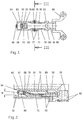
- a hinge fitting 55 for windows, doors or the like is shown, which is used according to FIG. 6 of the drawing as an upper hinge fitting 55 of a casement window 51 and there for mounting the wing 53 on the fixed frame 52 serves.
- the lower hinge fitting 54 of the casement window 51 according to FIG. 6 has a conventional design and therefore does not need to be explained in more detail.
- the upper hinge fitting 55 has a frame-side hinge band 56 with a hinge sleeve 57 located in front of the face-side end face of the fixed frame 52, into which a hinge pin 58 engages.
- This hinge pin 58 is above the hinge band 56 of the hinge sleeve 59 of another hinge band 60, which is connected to a fitting 61 which is attached to the upper horizontal leg of the wing 53, as can be seen in FIG. 6.
- the fitting 61 has integrally formed on its lower longitudinal edge, laterally ledge-like projecting foot parts 63, with which it can be inserted from the corner of the wing 53 into an undercut, for example C-shaped, profile groove 62, which leads to the wing corner is cut open.
- the arrangement and design of the profile groove 62 in the legs of the wing 53 can be seen in particular from FIG. 3 of the drawing.
- the fitting 61 is provided in its end wall 64 with an internal thread 65, as can be seen in particular in FIGS. 2 and 5. Doing so in this internal thread 65, a screw 66 is received as an actuator, as can be seen in FIGS. 1, 2, 4 and 6.
- the screw 66 At its end located outside the end wall 64 of the shaped piece 61, the screw 66 is provided with a tool engagement, for example a hexagon socket, while its other end projects into a window-like cutout 67 of the shaped piece and is shaped into a mushroom head 68. 2, 5 and 6 of the drawing it can be seen that the internal thread 65 and consequently also the screw 66 seated therein has an axis position which is inclined towards the horizontal, namely for this purpose at an acute angle 69 (FIG. 2). Via its mushroom head 68, the screw 66 is in positive engagement with an approximately C-shaped head piece 70 of a stop 71, which is indented from below into the window-like cutout 67 of the shaped piece 61, as can be seen particularly clearly from FIG. 2.
- a tool engagement for example a hexagon socket
- the head piece 70 of the stop 71 has lateral wings 72 (FIGS. 1 and 4), which come into operative connection in the window-like cutout 67 of the shaped piece 71 with guide strips 73, which end at a distance from the end wall 64 and on which they delimit the window-like cutout 67 Side walls of the molding 61 are formed (Fig. 5).
- the shaped piece 61 is not only cut out on its underside approximately over half its height, but it is also has lateral shoulders over a somewhat larger length range 75, so that only a relatively low and narrow longitudinal web 76 remains there.
- the shaped piece 61 forms longitudinal guide receptacles for a partial section of the stop 71 which encompasses and encompasses it, which, according to FIG. 3, has an approximately H-shaped cross section and is provided along its lower edge with foot parts 77 projecting sideways, which in a similar manner how the foot parts 63 of the shaped piece 61 can engage under the undercut parts of the profile groove 62 in the wing spar in a form-fitting manner.
- each fastening threaded bolt 80 has a pin-like punching projection 81 at its beginning of the shaft, which penetrates into the horizontal leg of a hook web and separates a material section therefrom in order to subsequently form-fit in the cutout formed thereby.
- each outside of the longitudinal web 76 of the fitting 61 gripping guide web 78 of the stopper 71 is provided near its upper edge with a projecting tongue 82, the lower edge of which comes to lie at the same height as the upper edge of a nose 83 , which projecting the molded piece 61 is formed laterally.
- Tongues 82 and lugs 83 interact with one another as a second group of guide strips between the shaped piece 61 and the stop 71. This in such a way that the superimposed support surfaces of both groups of guide strips assume approximately the same height from the underside of the shaped piece 61.
- both the front and the rear end of the stop 71 are provided with a longitudinally movable guide connection with the shaped piece 61.
- the element forming the actuator it can be moved beyond the area of longitudinal displacement Screw 66, the relative position of the fitting 61 with respect to the stop 71 can be adjusted continuously, provided the stop 61 is anchored via its fastening threaded bolts 80 in the hook webs of the wing spar delimiting the profile groove 62.
- An essential design feature of the hinge fitting 55 also lies in the fact that the hinge strap 56 can only be connected to the fitting 61 by means of a form-fitting plug-in coupling 84 (FIG. 4).
- the first coupling half 85 of this plug-in coupling 84 is formed by recesses 86 and projections 87 provided on the underside of the shaped piece 61, which are alternately adjacent to one another in the longitudinal direction of the shaped piece 61.
- recesses 86 and projections 87 are assigned to the two longitudinal edges of the shaped piece 61 symmetrically with respect to the longitudinal center plane thereof, which extends parallel to the wing plane.
- a tab 89 protruding from the articulation band 60 normal to the articulation axis thereof is used, which in the direction parallel to the articulation axis of the articulation band 60 has a profile 90 that is complementary to the recesses 86 and projections 87 of the first coupling half 85.
- the tab 89 has an approximately cross-shaped outline, so that its profile 90 fits positively without play in two adjacent notches 86 and between two adjacent projections 87 of the first coupling half 85.
- the tab 89 forming the second coupling half 88 is arranged on the hinge band 60 on a plane of symmetry crossing its hinge axis (FIG. 6) and that the profiling 90 extends uniformly over its entire thickness.
- the tab 89 is not only supported (as shown in FIG. 2) on the bottom of the profile groove 62, but it is also over the Total height of this profile groove 62 between the mutually facing surfaces of the bordering hook webs added.
- the recesses 86 and projections 87 forming the first coupling half 85 of the plug-in coupling 84 are provided on the shaped piece 61 in the area of the upright legs of the foot parts 63 which undercut the undercut parts of the profile groove 62 of the respective wing leg, while the second coupling half 88 forms the second coupling half 88
- Profiling 90 of the flap 89 on the hinge band 60 is formed by alternating lugs and indentations on the longitudinal edges thereof, as can be clearly seen in FIG. 4.
- a pin 91 for example with a round cross-sectional shape, protrude longitudinally from the underside of the shaped piece 60 and to which a correspondingly profiled hole 92 in the tab 89 of the hinge strap 60 is assigned.
Landscapes
- Engineering & Computer Science (AREA)
- Mechanical Engineering (AREA)
- Hinges (AREA)
Applications Claiming Priority (4)
| Application Number | Priority Date | Filing Date | Title |
|---|---|---|---|
| DE4234495 | 1992-10-14 | ||
| DE4234495 | 1992-10-14 | ||
| DE4234863 | 1992-10-15 | ||
| DE4234863A DE4234863A1 (de) | 1992-10-14 | 1992-10-15 | Scharnierbeschlag für die Flügel von Fenstern, Türen o. dgl. |
Publications (2)
| Publication Number | Publication Date |
|---|---|
| EP0592777A1 true EP0592777A1 (fr) | 1994-04-20 |
| EP0592777B1 EP0592777B1 (fr) | 1995-11-08 |
Family
ID=25919428
Family Applications (1)
| Application Number | Title | Priority Date | Filing Date |
|---|---|---|---|
| EP93111712A Expired - Lifetime EP0592777B1 (fr) | 1992-10-14 | 1993-07-22 | Ferrure de charnière pour battants de fenêtre, de portes ou similaires |
Country Status (3)
| Country | Link |
|---|---|
| EP (1) | EP0592777B1 (fr) |
| AT (1) | ATE130070T1 (fr) |
| ES (1) | ES2081168T3 (fr) |
Cited By (3)
| Publication number | Priority date | Publication date | Assignee | Title |
|---|---|---|---|---|
| EP0924375A1 (fr) | 1997-12-22 | 1999-06-23 | ROTO FRANK Aktiengesellschaft | Ferrure de charnière pour une aíle à battement de recouvrement d'une fenêtre, porte ou similaire |
| EP1757762A1 (fr) * | 2005-08-22 | 2007-02-28 | Roto Frank Ag | Articulation à charnière, pour fenêtres, portes ou similaires |
| US20180030769A1 (en) * | 2016-08-01 | 2018-02-01 | Wilh. Schlechtendahl & Söhne Gmbh & Co. Kg (Wss) | Leaf unit of a scissor mechanism of a fitting and method for installing such a leaf unit |
Citations (4)
| Publication number | Priority date | Publication date | Assignee | Title |
|---|---|---|---|---|
| DE7636855U1 (fr) * | Siegenia-Frank Kg, 5900 Siegen-Kaan- Marienborn | |||
| FR2131735A5 (fr) * | 1971-03-30 | 1972-11-10 | Siegenia Frank Kg | |
| DE2904869A1 (de) * | 1979-02-09 | 1980-08-14 | Bilstein August Fa | Ausstellarm fuer kipp-schwenk-fluegel von fenstern, tueren o.dgl. |
| DE8913790U1 (de) * | 1989-11-23 | 1990-01-11 | Siegenia-Frank Kg, 5900 Siegen | Scharniergelenk für Fenster, Türen o.dgl. |
-
1993
- 1993-07-22 EP EP93111712A patent/EP0592777B1/fr not_active Expired - Lifetime
- 1993-07-22 AT AT93111712T patent/ATE130070T1/de not_active IP Right Cessation
- 1993-07-22 ES ES93111712T patent/ES2081168T3/es not_active Expired - Lifetime
Patent Citations (4)
| Publication number | Priority date | Publication date | Assignee | Title |
|---|---|---|---|---|
| DE7636855U1 (fr) * | Siegenia-Frank Kg, 5900 Siegen-Kaan- Marienborn | |||
| FR2131735A5 (fr) * | 1971-03-30 | 1972-11-10 | Siegenia Frank Kg | |
| DE2904869A1 (de) * | 1979-02-09 | 1980-08-14 | Bilstein August Fa | Ausstellarm fuer kipp-schwenk-fluegel von fenstern, tueren o.dgl. |
| DE8913790U1 (de) * | 1989-11-23 | 1990-01-11 | Siegenia-Frank Kg, 5900 Siegen | Scharniergelenk für Fenster, Türen o.dgl. |
Cited By (6)
| Publication number | Priority date | Publication date | Assignee | Title |
|---|---|---|---|---|
| EP0924375A1 (fr) | 1997-12-22 | 1999-06-23 | ROTO FRANK Aktiengesellschaft | Ferrure de charnière pour une aíle à battement de recouvrement d'une fenêtre, porte ou similaire |
| DE19758907B4 (de) * | 1997-12-22 | 2007-10-25 | Roto Frank Ag | Einen Überschlag aufweisender Flügel eines Fensters, einer Tür oder dergleichen, mit einem Scharnierbeschlag sowie Montageverfahren des Scharnierbeschlags |
| EP1757762A1 (fr) * | 2005-08-22 | 2007-02-28 | Roto Frank Ag | Articulation à charnière, pour fenêtres, portes ou similaires |
| US20180030769A1 (en) * | 2016-08-01 | 2018-02-01 | Wilh. Schlechtendahl & Söhne Gmbh & Co. Kg (Wss) | Leaf unit of a scissor mechanism of a fitting and method for installing such a leaf unit |
| EP3279417A1 (fr) * | 2016-08-01 | 2018-02-07 | Wilh. Schlechtendahl & Söhne GmbH & Co. KG | Unite d'ailes d'une ferrure et procede de montage d'une telle unite d'ailes |
| US10480235B2 (en) * | 2016-08-01 | 2019-11-19 | Wilh. Schlechtendahl & Söhne Gmbh & Co. Kg (Wss) | Leaf unit of a scissor mechanism of a fitting and method for installing such a leaf unit |
Also Published As
| Publication number | Publication date |
|---|---|
| EP0592777B1 (fr) | 1995-11-08 |
| ATE130070T1 (de) | 1995-11-15 |
| ES2081168T3 (es) | 1996-02-16 |
Similar Documents
| Publication | Publication Date | Title |
|---|---|---|
| EP0403731B1 (fr) | Dispositif pour ouverture compas pour panneaux de fenêtres, portes ou similaires | |
| EP0644976A1 (fr) | Charniere | |
| CH624729A5 (fr) | ||
| EP2118414B1 (fr) | Armature de verrouillage et ensemble de pièces pour cette armature | |
| EP0789125A1 (fr) | Pièce porteuse pour élément de fermeture, de préférence pour vantail de porte pliante et coulissante | |
| DE102011006023B3 (de) | Verstellbares Scharnierband | |
| EP0478639B1 (fr) | Charniere | |
| EP0947654A1 (fr) | Charnière cachée | |
| EP0844348B1 (fr) | Penture pour portes ou fenêtres | |
| EP0592777B1 (fr) | Ferrure de charnière pour battants de fenêtre, de portes ou similaires | |
| EP0699815B1 (fr) | Dispositif de fixation par serrage pour la fixation d'une pièce de ferrure et procédé de fabrication d'un tel dispositif de fixation par serrage | |
| DE29719016U1 (de) | Fenster- oder Türverschluß | |
| DE4234863A1 (de) | Scharnierbeschlag für die Flügel von Fenstern, Türen o. dgl. | |
| DE202011052447U1 (de) | Anordnung einer Antriebseinheit einer Ausstell- oder Verriegelungseinrichtung | |
| EP0222067B1 (fr) | Dispositif de verrou de la tringle de commande pour fenêtres, portes ou similaires | |
| DE102005010067A1 (de) | Flügel und einen derartigen Flügel umfassende Schwingtür | |
| EP0246431A2 (fr) | Dispositif déflecteur pour panneau basculant, en particulier panneau oscillo-battant ou battant coulissant et basculant, de fenêtres, portes ou similaires | |
| DE2131852C3 (de) | Klappenscharnier | |
| DD295207A5 (de) | Ausstellvorrichtung fuer die fluegel von fenstern, tueren oder dergleichen | |
| EP0429981B1 (fr) | Ferrure arrangée en feuillure pour portes ou fenêtres oscillo-battantes, en particulier avec encadrement en bois | |
| EP1001123B1 (fr) | Penture de porte ou de fenêtre | |
| DE4419932C2 (de) | Lagerelement für die wenigstens drehbare Lagerung eines Flügels eines Fensters, einer Tür oder dergleichen | |
| DE19912839A1 (de) | Leicht montierbarer Zentralverschluß für Flügel | |
| EP0703339B1 (fr) | Fenêtre ou porte pivotante ou pivotante et basculante | |
| EP0616106B1 (fr) | Fenêtre ou porte avec ferrure de charnière |
Legal Events
| Date | Code | Title | Description |
|---|---|---|---|
| PUAI | Public reference made under article 153(3) epc to a published international application that has entered the european phase |
Free format text: ORIGINAL CODE: 0009012 |
|
| AK | Designated contracting states |
Kind code of ref document: A1 Designated state(s): AT BE CH DE DK ES FR GB GR IT LI NL PT |
|
| 17P | Request for examination filed |
Effective date: 19940428 |
|
| 17Q | First examination report despatched |
Effective date: 19950412 |
|
| GRAA | (expected) grant |
Free format text: ORIGINAL CODE: 0009210 |
|
| AK | Designated contracting states |
Kind code of ref document: B1 Designated state(s): AT BE CH DE DK ES FR GB GR IT LI NL PT |
|
| PG25 | Lapsed in a contracting state [announced via postgrant information from national office to epo] |
Ref country code: NL Free format text: LAPSE BECAUSE OF FAILURE TO SUBMIT A TRANSLATION OF THE DESCRIPTION OR TO PAY THE FEE WITHIN THE PRESCRIBED TIME-LIMIT Effective date: 19951108 Ref country code: GR Free format text: LAPSE BECAUSE OF FAILURE TO SUBMIT A TRANSLATION OF THE DESCRIPTION OR TO PAY THE FEE WITHIN THE PRESCRIBED TIME-LIMIT Effective date: 19951108 Ref country code: DK Effective date: 19951108 |
|
| REF | Corresponds to: |
Ref document number: 130070 Country of ref document: AT Date of ref document: 19951115 Kind code of ref document: T |
|
| ITF | It: translation for a ep patent filed | ||
| REF | Corresponds to: |
Ref document number: 59300897 Country of ref document: DE Date of ref document: 19951214 |
|
| GBT | Gb: translation of ep patent filed (gb section 77(6)(a)/1977) |
Effective date: 19951219 |
|
| REG | Reference to a national code |
Ref country code: CH Ref legal event code: NV Representative=s name: PATENTANWAELTE GEORG ROEMPLER UND ALDO ROEMPLER |
|
| REG | Reference to a national code |
Ref country code: ES Ref legal event code: FG2A Ref document number: 2081168 Country of ref document: ES Kind code of ref document: T3 |
|
| ET | Fr: translation filed | ||
| NLV1 | Nl: lapsed or annulled due to failure to fulfill the requirements of art. 29p and 29m of the patents act | ||
| PLBE | No opposition filed within time limit |
Free format text: ORIGINAL CODE: 0009261 |
|
| STAA | Information on the status of an ep patent application or granted ep patent |
Free format text: STATUS: NO OPPOSITION FILED WITHIN TIME LIMIT |
|
| 26N | No opposition filed | ||
| REG | Reference to a national code |
Ref country code: GB Ref legal event code: IF02 |
|
| PGFP | Annual fee paid to national office [announced via postgrant information from national office to epo] |
Ref country code: AT Payment date: 20020719 Year of fee payment: 10 |
|
| PGFP | Annual fee paid to national office [announced via postgrant information from national office to epo] |
Ref country code: BE Payment date: 20020722 Year of fee payment: 10 |
|
| PGFP | Annual fee paid to national office [announced via postgrant information from national office to epo] |
Ref country code: CH Payment date: 20020730 Year of fee payment: 10 |
|
| PG25 | Lapsed in a contracting state [announced via postgrant information from national office to epo] |
Ref country code: AT Free format text: LAPSE BECAUSE OF NON-PAYMENT OF DUE FEES Effective date: 20030722 |
|
| PG25 | Lapsed in a contracting state [announced via postgrant information from national office to epo] |
Ref country code: LI Free format text: LAPSE BECAUSE OF NON-PAYMENT OF DUE FEES Effective date: 20030731 Ref country code: CH Free format text: LAPSE BECAUSE OF NON-PAYMENT OF DUE FEES Effective date: 20030731 Ref country code: BE Free format text: LAPSE BECAUSE OF NON-PAYMENT OF DUE FEES Effective date: 20030731 |
|
| BERE | Be: lapsed |
Owner name: *SIEGENIA-FRANK K.G. Effective date: 20030731 |
|
| REG | Reference to a national code |
Ref country code: CH Ref legal event code: PL |
|
| PGFP | Annual fee paid to national office [announced via postgrant information from national office to epo] |
Ref country code: GB Payment date: 20040621 Year of fee payment: 12 |
|
| PG25 | Lapsed in a contracting state [announced via postgrant information from national office to epo] |
Ref country code: GB Free format text: LAPSE BECAUSE OF NON-PAYMENT OF DUE FEES Effective date: 20050722 |
|
| GBPC | Gb: european patent ceased through non-payment of renewal fee |
Effective date: 20050722 |
|
| PGFP | Annual fee paid to national office [announced via postgrant information from national office to epo] |
Ref country code: FR Payment date: 20060720 Year of fee payment: 14 |
|
| PG25 | Lapsed in a contracting state [announced via postgrant information from national office to epo] |
Ref country code: PT Free format text: LAPSE BECAUSE OF NON-PAYMENT OF DUE FEES Effective date: 19960408 |
|
| REG | Reference to a national code |
Ref country code: FR Ref legal event code: ST Effective date: 20080331 |
|
| PG25 | Lapsed in a contracting state [announced via postgrant information from national office to epo] |
Ref country code: FR Free format text: LAPSE BECAUSE OF NON-PAYMENT OF DUE FEES Effective date: 20070731 |
|
| PGFP | Annual fee paid to national office [announced via postgrant information from national office to epo] |
Ref country code: ES Payment date: 20080717 Year of fee payment: 16 |
|
| REG | Reference to a national code |
Ref country code: ES Ref legal event code: FD2A Effective date: 20090723 |
|
| PG25 | Lapsed in a contracting state [announced via postgrant information from national office to epo] |
Ref country code: ES Free format text: LAPSE BECAUSE OF NON-PAYMENT OF DUE FEES Effective date: 20090723 |
|
| PGFP | Annual fee paid to national office [announced via postgrant information from national office to epo] |
Ref country code: DE Payment date: 20110731 Year of fee payment: 19 |
|
| PGFP | Annual fee paid to national office [announced via postgrant information from national office to epo] |
Ref country code: IT Payment date: 20110721 Year of fee payment: 19 |
|
| PG25 | Lapsed in a contracting state [announced via postgrant information from national office to epo] |
Ref country code: DE Free format text: LAPSE BECAUSE OF NON-PAYMENT OF DUE FEES Effective date: 20130201 |
|
| REG | Reference to a national code |
Ref country code: DE Ref legal event code: R119 Ref document number: 59300897 Country of ref document: DE Effective date: 20130201 |
|
| PG25 | Lapsed in a contracting state [announced via postgrant information from national office to epo] |
Ref country code: IT Free format text: LAPSE BECAUSE OF NON-PAYMENT OF DUE FEES Effective date: 20120722 |