EP0592792A1 - Porte-tuyère pour paroi d'un haut fourneau - Google Patents
Porte-tuyère pour paroi d'un haut fourneau Download PDFInfo
- Publication number
- EP0592792A1 EP0592792A1 EP93113448A EP93113448A EP0592792A1 EP 0592792 A1 EP0592792 A1 EP 0592792A1 EP 93113448 A EP93113448 A EP 93113448A EP 93113448 A EP93113448 A EP 93113448A EP 0592792 A1 EP0592792 A1 EP 0592792A1
- Authority
- EP
- European Patent Office
- Prior art keywords
- armor
- windform
- wind
- tuyere
- casing
- Prior art date
- Legal status (The legal status is an assumption and is not a legal conclusion. Google has not performed a legal analysis and makes no representation as to the accuracy of the status listed.)
- Withdrawn
Links
Images


Classifications
-
- F—MECHANICAL ENGINEERING; LIGHTING; HEATING; WEAPONS; BLASTING
- F27—FURNACES; KILNS; OVENS; RETORTS
- F27B—FURNACES, KILNS, OVENS OR RETORTS IN GENERAL; OPEN SINTERING OR LIKE APPARATUS
- F27B1/00—Shaft or like vertical or substantially vertical furnaces
- F27B1/10—Details, accessories or equipment specially adapted for furnaces of these types
- F27B1/16—Arrangements of tuyeres
-
- C—CHEMISTRY; METALLURGY
- C21—METALLURGY OF IRON
- C21B—MANUFACTURE OF IRON OR STEEL
- C21B7/00—Blast furnaces
- C21B7/16—Tuyéres
Definitions
- the invention relates to a multi-part, cylindrical or frustoconical wind form armor between the frame and locking armor of a shaft furnace, in particular a blast furnace, for receiving the wind forms for the hot wind blowing.
- the cooling ring of a wind mold is inserted gas-tight in a wind mold holding frame.
- These windform holder frames are individually welded into openings in the windform armor.
- the required minimum size of the shaft mold frame for the shaft furnace determines the maximum number of wind molds that can be accommodated on the circumference and sets natural limits for a further specific increase in performance, especially for large blast furnaces.
- the compressed hot wind is blown into the interior of the blast furnace at high speed and should reach the center of the furnace as far as possible in order to ensure optimum gas flow through the column of furniture.
- wind mold holding frame because of the required tolerances, can only be inserted and welded into the assembled wind mold armor after extensive measurement.
- Another disadvantage is that the windform holder frame cannot be inserted into the windform armor in abutment, but at predetermined intervals, ie, for strength reasons, a minimum amount of windform armor must remain between the individual windform armor frames.
- the number of nozzle assemblies to be arranged on the circumference of the shaft furnace is limited by the dimensions of the windform holding frame and the diameter of the shaft furnace in the region of the windform armor.
- a nozzle assembly for blast furnace hot wind nozzles which is equipped with a resilient pressing device for the blowing nozzle.
- the nozzle assembly has at least two compression springs, which are arranged symmetrically to the axis of the blowing nozzle and act on radially projecting parts of the nozzle assembly end adjacent to the blowing nozzle and which are supported against adjusting nuts by retaining screws articulated on the furnace wall.
- a nozzle assembly in particular for a blast furnace, with a nozzle tip connected to a hot wind ring line is described in AT-PS 373 283.
- the nozzle tip opens into a full-walled wind form made of ceramic sintered mass.
- a cooled wind form box which delimits a cavity in the brick lining of the blast furnace is inserted into the brick lining of the furnace.
- the wind form is movably mounted with respect to the nozzle tip with the aid of a ball joint and is movable with respect to the wind form box by means of a further tight joint connection.
- the object of the invention is to accommodate the largest possible number of wind forms on the circumference of the wind form armor and thereby to make the cooling rings, which are arranged on the circumference of the wind form openings, so large that injection lances for additional fuels can be introduced without difficulty.
- annular windform armor With the help of curved (rolled) windform armor segment sheets, an annular windform armor can be formed. With the help of flat windform armor segment sheets, a polygonal windform armor can be formed.
- the curved or flat segment sheets are welded together to form a closed windform armor.
- the welding can be dispensed with if several windform openings are incorporated into a flat, correspondingly elongated segment sheet and this segment sheet is bent between two blow molds. In this way, a polygonal windform armor can also be created.
- This embodiment according to the invention offers the advantage over the designs according to the prior art that the number of windforms on the circumference of the windform armor increases and that, with the aid of modern machine technology and production methods, all of them Seating areas for the wind forms can already be machined in the workshop.
- the greater wall thickness of the windform armor sheets according to the invention places no special demands on today's workshop production.
- the otherwise necessary reinforcing collar for the wind form openings can be dispensed with.
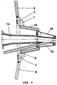
- Windform brackets (12) are welded into the windform armor (1), into which the cooling ring (13) for receiving the windform (15), to which a blowing lance (16) is let in, is fitted gas-tight through the windform cutout (6).
- the nozzle block tip (14) is connected to the nozzle block (not shown) with compensator, which is connected to the hot wind pipe.
- windform mounting frame (12) is also welded to the windform armor (1) on the bottom Frame armor (8) sits. Wind mold (1) and frame armor (8) are cooled in this area by double jacket cooling (17).
- FIG. 2 represents a segmental cutout of the entire annular windform armor (1).
- the windform armor (1) which consists of curved segment sheets (2) and serves to receive the cooling ring (13) and the windform (15) with a welded-in blowing lance (16).
- the wind form armor (1) has an approximately two to three times the wall thickness compared to the prior art. It is welded to the frame (8) at the bottom and to the locking armor (9) at the top.
- the seating area of the cooling ring (13) in the wind form opening (6) is designed in the workshop in such a way that a gas-tight connection is established after the cooling ring (13) has been introduced.
- Fig. 4 shows an arcuate section of the annular windform armor (4), which consists of curved windform armor segment sheets (2), in which the windform section (6) is incorporated.
- 5-6 shows a further, alternative solution for the execution of the windform armor (1).
- the polygonal windform armor (5) consists of individual flat windform armor segment sheets (3) of the same type Wall thickness, which are welded to each other via a butt seam (5a).
- the wind mold (15) with its cooling ring (13) is fitted directly into the wind mold cutout (6) and forms a gas-tight connection.
- Fig. 7 shows the windform armor (1) according to the invention, which is made of curved or flat segment sheets, with a cooling channel (7) incorporated circularly into the windform armor around each windform opening (6) with connections to the water cooling circuit of the blast furnace, not shown here.
Landscapes
- Engineering & Computer Science (AREA)
- Chemical & Material Sciences (AREA)
- Manufacturing & Machinery (AREA)
- Materials Engineering (AREA)
- Metallurgy (AREA)
- Organic Chemistry (AREA)
- Mechanical Engineering (AREA)
- General Engineering & Computer Science (AREA)
- Waste-Gas Treatment And Other Accessory Devices For Furnaces (AREA)
- Vertical, Hearth, Or Arc Furnaces (AREA)
Applications Claiming Priority (2)
| Application Number | Priority Date | Filing Date | Title |
|---|---|---|---|
| DE19924234936 DE4234936C1 (de) | 1992-10-16 | 1992-10-16 | Windformhalterung im Schachtofenpanzer |
| DE4234936 | 1992-10-16 |
Publications (1)
| Publication Number | Publication Date |
|---|---|
| EP0592792A1 true EP0592792A1 (fr) | 1994-04-20 |
Family
ID=6470641
Family Applications (1)
| Application Number | Title | Priority Date | Filing Date |
|---|---|---|---|
| EP93113448A Withdrawn EP0592792A1 (fr) | 1992-10-16 | 1993-08-24 | Porte-tuyère pour paroi d'un haut fourneau |
Country Status (2)
| Country | Link |
|---|---|
| EP (1) | EP0592792A1 (fr) |
| DE (1) | DE4234936C1 (fr) |
Citations (4)
| Publication number | Priority date | Publication date | Assignee | Title |
|---|---|---|---|---|
| DE607369C (de) * | 1932-03-30 | 1934-12-22 | Hans Rolfs | Dueseneinsatzkoerper zur Einfuehrung erhitzter Oberluft in Kupol- und Hochoefen |
| GB899445A (en) * | 1959-09-22 | 1962-06-20 | United States Steel Corp | Assembly for insertion in a blast furnace wall |
| GB1513274A (en) * | 1975-09-30 | 1978-06-07 | Sumitomo Metal Ind | Tuyeres |
| EP0451052A1 (fr) * | 1990-04-06 | 1991-10-09 | Savoie Refractaires | Perfectionnements à la réalisation des ouvreaux de brûleurs ou entourage de tuyères de fours et de réacteurs verticaux |
Family Cites Families (2)
| Publication number | Priority date | Publication date | Assignee | Title |
|---|---|---|---|---|
| US3480506A (en) * | 1964-08-20 | 1969-11-25 | Dow Chemical Co | Wood laminated with a modified ethylene polymer and a polyalkylene imine |
| AT373283B (de) * | 1982-04-05 | 1984-01-10 | Voest Alpine Ag | Duesenstock fuer einen schachtofen |
-
1992
- 1992-10-16 DE DE19924234936 patent/DE4234936C1/de not_active Expired - Lifetime
-
1993
- 1993-08-24 EP EP93113448A patent/EP0592792A1/fr not_active Withdrawn
Patent Citations (4)
| Publication number | Priority date | Publication date | Assignee | Title |
|---|---|---|---|---|
| DE607369C (de) * | 1932-03-30 | 1934-12-22 | Hans Rolfs | Dueseneinsatzkoerper zur Einfuehrung erhitzter Oberluft in Kupol- und Hochoefen |
| GB899445A (en) * | 1959-09-22 | 1962-06-20 | United States Steel Corp | Assembly for insertion in a blast furnace wall |
| GB1513274A (en) * | 1975-09-30 | 1978-06-07 | Sumitomo Metal Ind | Tuyeres |
| EP0451052A1 (fr) * | 1990-04-06 | 1991-10-09 | Savoie Refractaires | Perfectionnements à la réalisation des ouvreaux de brûleurs ou entourage de tuyères de fours et de réacteurs verticaux |
Also Published As
| Publication number | Publication date |
|---|---|
| DE4234936C1 (de) | 1993-10-28 |
Similar Documents
| Publication | Publication Date | Title |
|---|---|---|
| EP0481955B1 (fr) | Brûleur pour la combustion des combustibles solides à grains fins jusqu'aux combustibles solides pulvérulents | |
| DE102007044181B4 (de) | Füllteleskop zum Befüllen von Koksöfen | |
| DE2304875C2 (de) | Vorrichtung zum Einblasen von Heisswind in einen Schachtofen, insbesondere Hochofen | |
| EP0340207B1 (fr) | Lance de soufflage | |
| DE2034575C3 (de) | Mit einer wassergekühlten Blaslanze verbindbarer Düsenkopf | |
| AT405766B (de) | Schlusssteinset | |
| DE2344079A1 (de) | Ausgleichabschnitt fuer eine rohrleitung | |
| DE2018875A1 (de) | Vorrichtung zum Einblasen vorgewärmter Luft für öfen | |
| DE20213759U1 (de) | Kühlplatte für metallurgische Öfen | |
| DE4234936C1 (de) | Windformhalterung im Schachtofenpanzer | |
| DD202939A5 (de) | Kuehlvorrichtung fuer wandkonstruktionen und/oder deckelkonstruktionen von industrieoefen | |
| DE69808701T2 (de) | Metallurgisches Ofen Aggregat | |
| DE4107726A1 (de) | Vorrichtung zum einblasen von vorerhitzter luft in einen schachtofen | |
| DE19646802A1 (de) | Verfahren und Vorrichtung zum Betreiben eines Schachtofens | |
| EP0555725B1 (fr) | Dispositif d'installation de buses à gaz chaud ou de détente pour le raccordement d'appareillage d'admission d'air pour éliminer le collage ou l'accumulation de matière | |
| DE69615508T2 (de) | Düse zum einblasen von gas in schmelze und deren verwendung | |
| DE1302880C2 (de) | Metallurgischer tiegel mit muendungsring | |
| DE9213976U1 (de) | Windformhalterung im Schachtofen | |
| DE2421417C2 (de) | Vorrichtung zum Einblasen vorgewärmter Luft in einen Schachtofen, insbesondere Hochofen | |
| DE4443128A1 (de) | Rußbläsereinheit | |
| DE19541199C2 (de) | Wechselvorrichtung für eine Blaslanze | |
| EP0932805B1 (fr) | Souffleur a lance a eau pour nettoyage d'echangeurs de chaleur | |
| DE4136649C2 (de) | Heißwinddüsenstock für Schachtöfen, insbesondere Hochöfen | |
| EP0413925A1 (fr) | Système de refroidissement par air d'un récipient métallurgique monté dans un anneau de support | |
| EP1403603B1 (fr) | Element de raccordement pour un dispositif de refroidissement d'un four à cuve |
Legal Events
| Date | Code | Title | Description |
|---|---|---|---|
| PUAI | Public reference made under article 153(3) epc to a published international application that has entered the european phase |
Free format text: ORIGINAL CODE: 0009012 |
|
| AK | Designated contracting states |
Kind code of ref document: A1 Designated state(s): AT DE FR GB IT NL |
|
| 17P | Request for examination filed |
Effective date: 19940322 |
|
| 17Q | First examination report despatched |
Effective date: 19961210 |
|
| 18W | Application withdrawn |
Withdrawal date: 19970405 |