EP0592829B1 - Relais de surcharge a combiner a des contacteurs - Google Patents
Relais de surcharge a combiner a des contacteurs Download PDFInfo
- Publication number
- EP0592829B1 EP0592829B1 EP93114815A EP93114815A EP0592829B1 EP 0592829 B1 EP0592829 B1 EP 0592829B1 EP 93114815 A EP93114815 A EP 93114815A EP 93114815 A EP93114815 A EP 93114815A EP 0592829 B1 EP0592829 B1 EP 0592829B1
- Authority
- EP
- European Patent Office
- Prior art keywords
- contactors
- combined
- overload relay
- phase
- contactor
- Prior art date
- Legal status (The legal status is an assumption and is not a legal conclusion. Google has not performed a legal analysis and makes no representation as to the accuracy of the status listed.)
- Expired - Lifetime
Links
Images

Classifications
-
- H—ELECTRICITY
- H01—ELECTRIC ELEMENTS
- H01H—ELECTRIC SWITCHES; RELAYS; SELECTORS; EMERGENCY PROTECTIVE DEVICES
- H01H11/00—Apparatus or processes specially adapted for the manufacture of electric switches
- H01H11/0006—Apparatus or processes specially adapted for the manufacture of electric switches for converting electric switches
- H01H11/0031—Apparatus or processes specially adapted for the manufacture of electric switches for converting electric switches for allowing different types or orientation of connections to contacts
-
- H—ELECTRICITY
- H01—ELECTRIC ELEMENTS
- H01H—ELECTRIC SWITCHES; RELAYS; SELECTORS; EMERGENCY PROTECTIVE DEVICES
- H01H83/00—Protective switches, e.g. circuit-breaking switches, or protective relays operated by abnormal electrical conditions otherwise than solely by excess current
- H01H83/20—Protective switches, e.g. circuit-breaking switches, or protective relays operated by abnormal electrical conditions otherwise than solely by excess current operated by excess current as well as by some other abnormal electrical condition
- H01H83/22—Protective switches, e.g. circuit-breaking switches, or protective relays operated by abnormal electrical conditions otherwise than solely by excess current operated by excess current as well as by some other abnormal electrical condition the other condition being imbalance of two or more currents or voltages
- H01H83/223—Protective switches, e.g. circuit-breaking switches, or protective relays operated by abnormal electrical conditions otherwise than solely by excess current operated by excess current as well as by some other abnormal electrical condition the other condition being imbalance of two or more currents or voltages with bimetal elements
-
- H—ELECTRICITY
- H01—ELECTRIC ELEMENTS
- H01H—ELECTRIC SWITCHES; RELAYS; SELECTORS; EMERGENCY PROTECTIVE DEVICES
- H01H11/00—Apparatus or processes specially adapted for the manufacture of electric switches
- H01H11/0006—Apparatus or processes specially adapted for the manufacture of electric switches for converting electric switches
- H01H11/0031—Apparatus or processes specially adapted for the manufacture of electric switches for converting electric switches for allowing different types or orientation of connections to contacts
- H01H2011/0037—Apparatus or processes specially adapted for the manufacture of electric switches for converting electric switches for allowing different types or orientation of connections to contacts with removable or replaceable terminal blocks
-
- H—ELECTRICITY
- H01—ELECTRIC ELEMENTS
- H01H—ELECTRIC SWITCHES; RELAYS; SELECTORS; EMERGENCY PROTECTIVE DEVICES
- H01H89/00—Combinations of two or more different basic types of electric switches, relays, selectors and emergency protective devices, not covered by any single one of the other main groups of this subclass
- H01H89/06—Combination of a manual reset circuit with a contactor, i.e. the same circuit controlled by both a protective and a remote control device
Definitions
- the invention relates to overload relays according to the preamble of claim 1.
- it relates to overload relays with thermally delayed overcurrent tripping, with magnetic short-circuit tripping or with a combination of both types of tripping, but also with overload relays equipped with current transformers.
- a typical area of application is motor protection.
- An overload relay to be combined with a contactor with bimetal releases for each current phase to be protected is known from FR 2 625 603 A1.
- this overload relay On the side facing the contactor, this overload relay has fixed built-in plug connections as phase connections, which can be connected to the terminal connections of the contactor.
- the plug connections On the one hand, the plug connections are in the phase distance and in the phase height, i.e.
- the connection geometry is compatible with the terminal connections of the contactor and, on the other hand, the overload relay can be snapped onto the contactor.
- the overload relay On the side facing the load, the overload relay has permanently installed terminal connections as phase connections.
- the terminal connections of the overload relay do not match the terminal connections of the contactor in terms of their connection geometry, which makes it difficult for the user to configure, install, maintain and maintain.
- the scope of application is limited to the combination with contactors of the same type and size. It is not possible to set up the components often with this solution.
- the overload relay is provided on both sides with flat connections that have holes for screw connections and are compatible with the flat connections of the contactor in terms of their connection type and geometry.
- the disadvantage of these solutions remains that the overload relays cannot be combined with contactors of different connection types and geometries, or only in a complex manner. Comparable problems arise with regard to different phase conductors coming from the overload relay and leading to the load.
- an overload relay with load-side terminal connections is designed as a basic device, to which a contact-side connection block designed as a housing-free connection angle module is screwed in a height-adjustable manner within certain limits.
- the connection brackets are plug-in connections which enable direct connection to a contactor - but only if the contactor is equipped with terminal connections.
- the overload relay can only be attached to an assembly base using the basic device.
- a connection block with terminal connections is provided for the individual installation of the overload relay.
- an overload relay is known from DE 84 34 232 U1 that consists of a basic device with load-side terminal connections and a contactor-side, housing-encapsulated connection block.
- the connection block is detachably connected electrically via plug connections and mechanically to the basic device via snap connections.
- the overload relay With a connection block provided with terminal connections, the overload relay is suitable for stand-alone installation.
- the overload relay can be combined directly with a contactor thanks to a connection block provided with plug connections - but only if this is equipped with terminal connections.
- the overload relay can also be connected to contactors with different phase spacings by selecting the elbow of the plug connections.
- the load-side compatibility of the overload relay with regard to the phase distance of a contactor is also provided - however, a load-side adaptation to contactors with different phase distances is not possible. It can only be attached to an assembly base using the basic device. The plug connection between the basic device and the connection block makes the overload relay unsuitable for use in higher current ranges.
- a switching device known according to EP 219 570 A1 with actuatable main contact bridges and with associated fixed contact rails, each leading out of opposite side walls of the switch housing, is provided on each of these side walls with a housing bracket.
- the housing brackets contain the connection screws required for connection with ordinary connecting cables and can be attached in two positions rotated by 180 ° to one another, so that the connection screws can be actuated either from the front or the rear of the housing, the housing brackets via the free ends of the Grip the fixed contact rails and connect them with the connecting screws.
- An electromagnetic switching device known from DE 30 37 405 A1 has a housing part which is detachably connected to insulating material bodies. For each pole to be switched, a connection terminal and a fixed contact rail permanently connected to it are embedded in the insulating bodies.
- the insulating material bodies are suitable for being able to change the number and / or the quality of the fixed contact rails for the purpose of adaptation to the requirements of the contactor. With different fixed contact rails, both terminal connections and flat plug connections for cable or wire connections can be implemented within the connection openings of the insulating body.
- connection blocks that can be connected to the basic device in a simple manner can be the same or different on the contactor and load side in order to meet the most varied connection and combination possibilities with regard to the associated contactor and the load side.
- the modules of the overload relay can each be mounted individually or conveniently only via the connection blocks on the assembly base. When assembled together, the basic device is also supported. The latter takes place in a particularly advantageous manner via the mechanical and electrical connection of the connection blocks to the basic device.
- the compatibility of the terminal block on the contactor side serves in particular to directly connect the overload relay and contactor.
- the sub-claim 2 specifies an advantageous embodiment of the solution according to claim 1.
- the load-side compatibility of the connection block facilitates, among other things. for the user, the geometric and functional assignment of the load side of the overload relay to the output side of the contactor and thus promotes understanding of the system (so-called recognition value and degree of familiarity).
- the terminal blocks come from a series which advantageously meet the connection conditions for combining the overload relay with different contactors, which - apart from the differences in the electrical parameters - differ in terms of their connection type, their phase height and their phase spacing.
- the connection blocks thus also satisfy different embodiments of phase conductors on the output side or, if appropriate, downstream switching devices.
- the terminal blocks of the series can in principle be used both on the contactor side and on the load side. For a multitude of combinations with different contactors, this flexible module system - of course taking into account the electrical conditions - only requires a single basic device of the overload relay.
- the base unit can be adapted to the respective connection conditions in a suitable, generally different manner, both on the contactor side and on the load side.
- the module system can be adapted to any newly developed contactor in a contactor series and any other to a newly developed contactor series from the same manufacturer or to contactors from other manufacturers. It is also possible to retrofit a circuit with a contactor with an overload relay, whereby - as is generally desired - the load-side connection type and connection geometry can be obtained, which brings considerable advantages for the user, inter alia through the use of the same tools for connecting the contactor and Overload relay.
- claim 4 and in particular of claim 5 are reliable means for the simultaneous mechanical and electrical connection of the terminal blocks with the basic device.
- the features of claims 6 and 7 are used to adapt the overload relay to different phase distances and heights.
- the basic device is a fully-fledged device for overload protection in electrical terms. In this case, the connections on the contactor and load side could possibly be made via the means of the screw connections on the basic device.
- the plug connections according to claim 8 enable in particular the direct connection of the overload relay to a contactor via its relay-side terminal connections. It is particularly advantageous if an identically constructed plug-in block of the contactor is used as the connection block.
- the design of the plug connections according to claim 10 results in a particularly advantageous connection possibility between the connection block and the basic device.
- the flat connections of the plug connections designed according to claim 11 allow not only the plug connection via terminal connections of a contactor but also the screw connection with flat connections a contactor or with incoming or outgoing flat conductors.
- the feature according to claim 12, in particular in a simple embodiment according to claim 13, allows the phase connections of the overload relay to be adapted to the phase height of the relay-side contactor connections or to other incoming or outgoing connections or conductors within certain limits.
- an overload relay provided with plug-in connections can be retrofitted with terminal connections in order, for example, to enable its individual installation in a simple manner. It is particularly advantageous if, according to claim 15, a terminal carrier that can be taken over by the contactor is used, which, for example, when the terminal carrier is used on the load side in the interest of understanding the system for the user, gives the same visual impression at the outputs of the contactor and the overload relay.
- the terminal connections according to claim 16 also serve for the individual installation of the overload relay and for easier understanding of the system.
- the arrangement of the screw connection between the terminal block and basic device according to claim 17 is particularly useful.
- a terminal block which can be taken over by the contactor has the advantages already mentioned with claim 15.
- the use of box terminals according to claim 19 is also expedient.
- the covering of the terminal connections according to claim 20 serves to protect against contact and is particularly expedient in the case of a cover hood that can be taken over by the contactor according to claim 21.
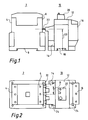
- the contactor contains, for each of the three phases, mains-side terminal connections 4 and relay-side terminal connections 6.
- the contactor 2 also contains snap fastening means 8 for snapping the contactor 2 onto a top-hat rail, not shown.
- the overload relay 10 consists of a basic device 12, a contactor-side connection block 14 and a load-side connection block 16.
- the basic device 12 contains known overload protection devices for protecting the downstream load against overload, in particular against overcurrent, and is encapsulated in a molded housing.
- the basic device 12 has snap fastening means 18 on its underside.
- An auxiliary switch 20 known per se is attached to its upper side.
- the contactor-side connection block 14 is encapsulated in a molded housing and contains three phase connections designed as plug connections 22, which project into the terminal spaces of the relay-side terminal connections 6 of the contactor 2 and are connected to them. There is thus compatibility, that is to say both the type of connection as well as the connection geometry defined by the phase distance 21 and the phase height 23, between the relay-side phase connections of the contactor 2 and the contactor-side phase connections of the overload relay 10.
- the load-side connection block 16 is also encapsulated in a molded housing and contains three phase connections designed as terminal connections.
- the connection blocks 14 and 16 each have on their undersides two screw fastening means 24 in the form of lateral approaches with openings.
- the three modules basic device 12, contactor-side connection block 14 and load-side connection block 16 are mechanically and electrically connected to one another in a manner described in more detail below.
- the overload relay 10 can either be fastened on a top hat rail (not shown) using the snap fastening means 18 of the basic device 12 or solely on a mounting plate using the screw fastening means 24 of the connection blocks 14 and 16.
- the overload relay 10 corresponds in its load-side connection type and geometry to the relay-side connection type and geometry of the contactor 2. This coincidence of the phase connections considerably simplifies the understanding of the system and the handling of the system components by the recognition effect for the user.
- connection plates 34 made of conductive material are fastened in phases by means of grooves 36 and retaining screws 38.
- the connection plates 34 are partially accessible from the outside through rectangular openings 40 and have threaded bores 42 in these areas.
- connection plates 34, grooves 36, retaining screws 38, openings 40, threaded holes 42, blind holes 44, connecting lugs 46 and openings 48 are arranged on the opposite molded housing surface facing the contact-side connection block 14.
- the contactor-side connection block 14 consists of a molded housing in the form of a rib-reinforced molded shell 50 and the three plug connections 22.
- the plug connections 22 merge in one piece into a first connection piece 52 bent at right angles.
- the plug connections 22 or connecting pieces 52 are inserted between two L-shaped protrusions 54 which are directed upwards and arranged approximately in phase height. They are limited in their vertical movement downwards by the upper inner transverse rib 56 and upwards by applying two lateral stop angles 58 of the first connection pieces 52 to the upper, horizontal legs of the L-shaped formations 54.
- the inserted plug connections 22 or connection pieces 52 are limited by the application of the stop angle 58 to the lower, vertical legs of the L-shaped formations 54.
- two downward-pointing connecting pins 60 are formed on the lower part of the molded shell 50 and two pins 62 directed towards the basic device 12 in the upper half of the molded shell 50.
- the actual electrical and mechanical connection is made by three socket head screws 64, each of which extends with its shaft through an elongated hole 66 of the vertically directed legs of the first connecting pieces 52 and is screwed into the threaded bores 42 of the associated connecting plates 34 of the basic device 12. This is done with the aid of a screwdriver 68, which engages with its tip through a screw opening 70 inserted in the molded shell 50 below the plug connections 22 and acts in the direction of the phase access.
- the type of mounting of the plug connections 22 or connection pieces 52 in the molded shell 50 and the connection via the elongated holes 66 allow, within certain limits, the phase height of the plug connections 22 - and thus the phase height of the overload relay on the contactor side - to be adapted to the phase height of the upstream contactor .
- the load-side connection block 16 consists of a further molded housing 72 and three clamp connections mounted therein, which are designed as frame clamps 74.
- a second connection piece 78 which is bent at right angles, is inserted between two parallelepiped-shaped formations 76 of the further molded housing 72 in the middle height of the frame clamps 74.
- the load-side connection block 16 is locked in the associated openings 48 and blind holes 44 of the basic device 12 by means of two connecting pins 60 and two pins 62.
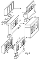
- FIG. 6 illustrates how the basic device 12 can be connected on the contactor side in addition to the contact-side connection block 14 described with FIG. 4 with a selection of further connection blocks 114, 214, and 314 from a series in order to meet a wide variety of connection conditions.
- the contactor-side connection block 114 shown in the lower part of the figure is provided with plug-in connections designed to form flat connections 82 and provided with connecting bores 84.
- the flat connections 82 can be clamped directly to suitable terminal connections of a contactor, they can be screwed directly to compatible flat connections of a contactor, but they can also be connected to flat conductors when the components of the contactor and overload relay are installed individually, which are connected at the other end to a contactor.
- connection carrier designed as a box terminal block 86 is pushed onto the flat connections 82 and mechanically and electrically connected to them via screws, not shown.
- An additional advantage here is that a connection carrier is used as box terminal block 86, which comes from the contactor series to be combined with the overload relay.
- the contact-side connection block 214 shown in the middle also has plug connections 88 as phase connections, which merge in one piece into third connection pieces 89. In order to establish compatibility with regard to the connection geometry of larger contactors, the third connection pieces 89 were made in two to one another vertical directions.
- the contactor-side connection block 314 shown in the upper part of the figure is used for the individual installation of the components and is equipped with known terminal connections, into which the phase conductors coming from the contactor can be hung from above. After the phase conductors have been connected, the terminal connections 90 are secured against contact by a cover 92 which can be fitted from the front. A further advantage here is that the cover 92 was taken over by a contactor of the row of contactors to be combined with the overload relay.
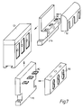
- FIG. 7 illustrates how the basic device 12 can be connected on the load side in addition to the load-side connection block 16 described with FIG. 5, with a selection of further connection blocks 116 and 216 from a series, in order to satisfy the most varied of closing conditions.
- the load-side connection block 116 shown in the lower part of the figure is identical to the contact-side connection block 114 from FIG. 6.
- the flat connections 82 are connected to flat conductors which are connected at the other end to the load. If necessary, the box terminal block 86 already described with FIG. 6 can be placed on the flat connections 82.
- the load-side connection block 216 with terminal connections 90 shown in the upper part of FIG. 7 is in turn identical to the protective-side connection block 314 explained in more detail in FIG. 6.
- the cover 92 has also already been described there.
Landscapes
- Engineering & Computer Science (AREA)
- Manufacturing & Machinery (AREA)
- Connections Arranged To Contact A Plurality Of Conductors (AREA)
- Fuses (AREA)
Claims (27)
- Relais de surcharge combinable à des contacteurs-disjoncteurs, rangé entre un contacteur-disjoncteur (2) et la résistance de charge électrique à relier et à protéger de la surcharge, le relais de surcharge (10) consistant en un appareil de base (12) enfermé dans un boîtier moulé (26) et contenant les organes de protection contre la surcharge, et en un bloc de connexion (14; 114; 214; 314) côté contacteur-disjoncteur démontable, raccordé à l'appareil de base (12) tant électriquement que mécaniquement, pourvu de connexions de phase (22; 82; 88; 90) et mis sous boîtier moulé, ledit bloc de connexion étant compatible au contacteur-disjoncteur (2) monté en amont, relativement au mode de raccordement de ses connexions de phase (22; 82; 88; 90) de même que relativement à l'intervalle de phase (21) de celles-ci, caractérisé en ce que- un bloc de connexion (16; 116; 216) est prévu, raccordé côté charge pourvu de connexions de phase (74; 82; 90), mis sous boîtier moulé, semblablement raccordé électriquement et mécaniquement et de manière à pouvoir être démonté avec l'appareil de base (12),- des raccords à vis (42, 64, 66; 42, 64, 80) sont prévus pour le raccordement électrique au moins partiellement mécanique entre appareil de base (12) et blocs de connexion (14; 16; 114; 116; 214; 216; 314),- les blocs de connexion (14; 16; 114; 116; 214; 216; 314) au moins, présentent des moyens de fixation (18; 24) sur une base de montage et- le bloc de fixation (14; 114; 214; 314) côté contacteur-disjoncteur est également compatible avec le contacteur-disjoncteur (2) monté en amont, relativement à la hauteur de phase (23) de ses connexions de phase (22; 82; 88; 90).
- Relais de surcharge combinable à des contacteurs-disjoncteurs selon revendication 1, caractérisé en ce que le bloc de connexion (16; 116; 216) côté charge est compatible avec le contacteur-disjoncteur (2) monté en amont, relativement au mode de connexion de ses connexions de phase (74; 82; 90) et/ou à l'intervalle de phase de celles-ci et/ou à leur hauteur de phase.
- Relais de surcharge combinable à des contacteurs-disjoncteurs selon l'une des revendications 1 et 2, caractérisé en ce que les blocs de connexion (14; 16; 114; 116; 214; 216; 314) appartiennent à une gamme de fabrication, laquelle est compatible avec au moins deux contacteurs-disjoncteurs différents par leur mode de raccordement et/ou par leur intervalle de phase (21) et/ou par leur hauteur de phase (23).
- Relais de surcharge combinable à des contacteurs-disjoncteurs selon l'une des revendications précédentes, caractérisé en ce que- l'appareil de base (12) contient côté accès et sortie, pour chaque phase une plaque de raccordement (34) respective accessible de l'extérieur, laquelle est fixée au boîtier moulé (26) par force élastique et par engagement positif,- pour chaque phase une pièce de connexion (52; 78) est logée par engagement positif dans les boîtiers moulés (50; 72) des blocs de connexion (14; 16) et qu'elle est un élément constituant, mécanique et électrique, de la connexion de phase (22; 74),- les pièces de connexion (52; 78) sont raccordées aux plaques de raccordement (34) respectives par les raccords à vis (42, 64, 66; 42, 64, 80) accessibles de l'extérieur.
- Relais de surcharge combinable à des contacteurs-disjoncteurs selon revendication 4,caractérisé en ce que- les plaques de raccordement (34) sont alignée parallèlement aux surfaces (32) de boîtier moulé de l'appareil de base (12), sur le côté du bloc de connexion,- les pièces de connexion (52; 78) sont courbées à angle droit et par un côté adhèrent par affleurement à la plaque de raccordement (34) correspondante, - les raccords à vis (42, 64, 66; 42, 64, 80) sont dirigés parallèlement à l'accès et à la sortie de phase.
- Relais de surcharge combinable à des contacteurs-disjoncteurs selon revendication 4 ou 5, caractérisé en ce que toutes les pièces de connexion (89) d'un des deux blocs de connexion (214) au moins, n'étant pas associées à la phase médiane, sont coudées dans un plan parallèle au plan de montage.
- Relais de surcharge combinable à des contacteurs-disjoncteurs selon l'une des revendications 4 à 6, caractérisé en ce que toutes les pièces de connexion (89) d'un des deux blocs de connexion (214) au moins, sont coudées parallèlement au plan de montage.
- Relais de surcharge combinable à des contacteurs-disjoncteurs selon l'une des revendications précédentes, caractérisé en ce que les connexions de phase d'un des deux blocs de connexion (14; 114; 116; 214) au moins sont des prises embrochables (22; 82; 88).
- Relais de surcharge combinable à des contacteurs-disjoncteurs selon revendication 8, caractérisé en ce que le bloc de connexion (14; 114; 116; 214) est de construction identique à un bloc embrochable raccordé à un contacteur-disjoncteur de manière à pouvoir en être démonté.
- Relais de surcharge combinable à des contacteurs-disjoncteurs selon revendication 9 associée à l'une des revendications 4 à 7, caractérisé en ce que les prises embrochables (22; 88) se prolongent d'une seule pièce dans les pièces de connexion (52; 89).
- Relais de surcharge combinable à des contacteurs-disjoncteurs selon revendication 8 ou 10, caractérisé en ce que les prises embrochables sont formées comme connexions plates (82) pourvues de perçages de raccordement (84).
- Relais de surcharge combinable à des contacteurs-disjoncteurs selon l'une des revendications 8 à 11 associée à revendication 4 ou 5, caractérisé en ce que les prises embrochables (22) sont fixées de manière à pouvoir être réglées au moyen des raccords à vis (42, 64, 66), pour ce qui est de leur hauteur de phase (23).
- Relais de surcharge combinable à des contacteurs-disjoncteurs selon revendication 12, caractérisé en ce que des trous oblongs (66) sont prévus pour les raccords à vis (42, 64, 66).
- Relais de surcharge combinable à des contacteurs-disjoncteurs selon l'une des revendications 8 à 13, caractérisé en ce qu'un support de raccordement formé comme bloc de bornes-cadres (86) est poussé sur les prises embrochables (82), et raccordé à elles de manière à pouvoir en être retiré.
- Relais de surcharge combinable à des contacteurs-disjoncteurs selon revendication 14, caractérisé en ce que le bloc de bornes-cadres (86) est de construction identique à un support de raccordement d'un contacteur-disjoncteur combinable.
- Relais de surcharge combinable à des contacteurs-disjoncteurs selon l'une des revendications précédentes, caractérisé en ce que les connexions de phase sont des bornes serrées (74; 90) d'un des deux blocs de connexion (16; 216; 314) au moins.
- Relais de surcharge combinable à des contacteurs-disjoncteurs selon revendications 5 et 16, caractérisé en ce que les raccords à vis (42, 64, 80) sont accessibles par la chambre de borne des connexions serrées (74).
- Relais de surcharge combinable à des contacteurs-disjoncteurs selon revendication 16 ou 17, caractérisé en ce que le bloc de connexion (16; 216; 314) est de construction identique à un répartiteur raccordé à un contacteur-disjoncteur combinable de manière à pouvoir en être retiré.
- Relais de surcharge combinable à des contacteurs-disjoncteurs selon revendication 16 ou 17, caractérisé en ce que les connexions serrées sont formées comme des bornes-cadres (74).
- Relais de surcharge combinable à des contacteurs-disjoncteurs selon l'une des revendications 16 à 19, caractérisé en ce qu'un couvercle (81; 92) est prévu pour les connexions serrées (74; 90) d'un des deux blocs de connexion (16; 216; 314) au moins.
- Relais de surcharge combinable à des contacteurs-disjoncteurs selon revendication 20, caractérisé en ce que le couvercle (92) est de construction identique au couvercle d'un contacteur-disjoncteur combinable.
- Relais de surcharge combinable à des contacteurs-disjoncteurs selon l'une des revendications précédentes, caractérisé en ce que les blocs de connexion (14, 16) sont fixés sur l'appareil de base (12), de manière à pouvoir en être démontés, par des moyens de raccordement mécaniques supplémentaires (46, 48, 60; 44, 62).
- Relais de surcharge combinable à des contacteurs-disjoncteurs selon revendication 22, caractérisé en ce que des parties des moyens de raccordement mécaniques supplémentaires (46) sont des creux sur le fond, lesquels sont formés comme évidements (48) pour la fixation par vis sur une plaque de montage ou similaire.
- Relais de surcharge combinable à des contacteurs-disjoncteurs selon l'une des revendications précédentes, caractérisé en ce que les moyens de fixation sur une base de montage sont des moyens de fixation à vis (24).
- Relais de surcharge combinable à des contacteurs-disjoncteurs selon l'une des revendications 1 à 23, caractérisé en ce que les moyens de fixation sur une plaque de montage sont des moyens de fixation par verrouillage immédiat (18).
- Relais de surcharge combinable à des contacteurs-disjoncteurs selon revendication 23 ou 24, caractérisé en ce que sont prévus des moyens de fixation à verrouillage immédiat supplémentaires.
- Relais de surcharge combinable à des contacteurs-disjoncteurs selon l'une des revendications précédentes, caractérisé en ce qu'un interrupteur auxiliaire (20) est fixé de manière à pouvoir être démonté sur la face supérieure de l'appareil de base (12).
Applications Claiming Priority (2)
| Application Number | Priority Date | Filing Date | Title |
|---|---|---|---|
| DE4234619A DE4234619C2 (de) | 1992-10-14 | 1992-10-14 | Mit Schützen zu kombinierendes Überlastrelais |
| DE4234619 | 1992-10-14 |
Publications (2)
| Publication Number | Publication Date |
|---|---|
| EP0592829A1 EP0592829A1 (fr) | 1994-04-20 |
| EP0592829B1 true EP0592829B1 (fr) | 1997-04-09 |
Family
ID=6470436
Family Applications (1)
| Application Number | Title | Priority Date | Filing Date |
|---|---|---|---|
| EP93114815A Expired - Lifetime EP0592829B1 (fr) | 1992-10-14 | 1993-09-15 | Relais de surcharge a combiner a des contacteurs |
Country Status (5)
| Country | Link |
|---|---|
| US (1) | US5483212A (fr) |
| EP (1) | EP0592829B1 (fr) |
| AT (1) | ATE151564T1 (fr) |
| DE (1) | DE4234619C2 (fr) |
| ES (1) | ES2101184T3 (fr) |
Families Citing this family (96)
| Publication number | Priority date | Publication date | Assignee | Title |
|---|---|---|---|---|
| US5606299A (en) * | 1995-11-14 | 1997-02-25 | Eaton Corporation | Modular surge suppressor |
| US5652420A (en) * | 1995-11-14 | 1997-07-29 | Eaton Corporation | Modular contactor control system |
| DE19600557A1 (de) * | 1996-01-09 | 1997-07-17 | Siemens Ag | Verdrahtungsbaustein |
| AP854A (en) * | 1996-05-10 | 2000-07-03 | Circuit Breaker Industries Ltd | Modular circuit breaker interconnection system. |
| DE19727732B4 (de) * | 1997-06-30 | 2009-08-06 | Abb Ag | Kombinationsschaltgerät |
| IT1292453B1 (it) | 1997-07-02 | 1999-02-08 | Aeg Niederspannungstech Gmbh | Gruppo rotante di contatti per interrutttori di alta portata |
| JP3213573B2 (ja) * | 1997-10-30 | 2001-10-02 | 松下電工株式会社 | スイッチ内蔵制御機器 |
| DE19819242B4 (de) | 1998-04-29 | 2005-11-10 | Ge Power Controls Polska Sp.Z.O.O. | Thermomagnetischer Leistungsschalter |
| US6114641A (en) | 1998-05-29 | 2000-09-05 | General Electric Company | Rotary contact assembly for high ampere-rated circuit breakers |
| US6087913A (en) | 1998-11-20 | 2000-07-11 | General Electric Company | Circuit breaker mechanism for a rotary contact system |
| US6037555A (en) | 1999-01-05 | 2000-03-14 | General Electric Company | Rotary contact circuit breaker venting arrangement including current transformer |
| DE19901675A1 (de) * | 1999-01-18 | 2000-07-20 | Abb Patent Gmbh | Abdeckhaube für ein thermisches Überstromrelais |
| US6166344A (en) | 1999-03-23 | 2000-12-26 | General Electric Company | Circuit breaker handle block |
| US6262872B1 (en) | 1999-06-03 | 2001-07-17 | General Electric Company | Electronic trip unit with user-adjustable sensitivity to current spikes |
| US6268991B1 (en) | 1999-06-25 | 2001-07-31 | General Electric Company | Method and arrangement for customizing electronic circuit interrupters |
| US6218917B1 (en) | 1999-07-02 | 2001-04-17 | General Electric Company | Method and arrangement for calibration of circuit breaker thermal trip unit |
| US6188036B1 (en) | 1999-08-03 | 2001-02-13 | General Electric Company | Bottom vented circuit breaker capable of top down assembly onto equipment |
| US6710988B1 (en) | 1999-08-17 | 2004-03-23 | General Electric Company | Small-sized industrial rated electric motor starter switch unit |
| US6252365B1 (en) | 1999-08-17 | 2001-06-26 | General Electric Company | Breaker/starter with auto-configurable trip unit |
| US6396369B1 (en) | 1999-08-27 | 2002-05-28 | General Electric Company | Rotary contact assembly for high ampere-rated circuit breakers |
| DE29916001U1 (de) * | 1999-09-13 | 2000-01-05 | Abb Patent Gmbh, 68309 Mannheim | Installationsschalter |
| US6232570B1 (en) | 1999-09-16 | 2001-05-15 | General Electric Company | Arcing contact arrangement |
| US6326869B1 (en) | 1999-09-23 | 2001-12-04 | General Electric Company | Clapper armature system for a circuit breaker |
| US6239395B1 (en) | 1999-10-14 | 2001-05-29 | General Electric Company | Auxiliary position switch assembly for a circuit breaker |
| US6229413B1 (en) | 1999-10-19 | 2001-05-08 | General Electric Company | Support of stationary conductors for a circuit breaker |
| US6317018B1 (en) | 1999-10-26 | 2001-11-13 | General Electric Company | Circuit breaker mechanism |
| US6232856B1 (en) | 1999-11-02 | 2001-05-15 | General Electric Company | Magnetic shunt assembly |
| US6377144B1 (en) | 1999-11-03 | 2002-04-23 | General Electric Company | Molded case circuit breaker base and mid-cover assembly |
| EP1098343B1 (fr) | 1999-11-03 | 2005-09-21 | AEG Niederspannungstechnik GmbH & Co. KG | Dispositif a contact tournant pour disjoncteur |
| US6300586B1 (en) | 1999-12-09 | 2001-10-09 | General Electric Company | Arc runner retaining feature |
| US6310307B1 (en) | 1999-12-17 | 2001-10-30 | General Electric Company | Circuit breaker rotary contact arm arrangement |
| US6184761B1 (en) | 1999-12-20 | 2001-02-06 | General Electric Company | Circuit breaker rotary contact arrangement |
| US6172584B1 (en) | 1999-12-20 | 2001-01-09 | General Electric Company | Circuit breaker accessory reset system |
| US6215379B1 (en) | 1999-12-23 | 2001-04-10 | General Electric Company | Shunt for indirectly heated bimetallic strip |
| US6281461B1 (en) | 1999-12-27 | 2001-08-28 | General Electric Company | Circuit breaker rotor assembly having arc prevention structure |
| US6346869B1 (en) | 1999-12-28 | 2002-02-12 | General Electric Company | Rating plug for circuit breakers |
| US6211758B1 (en) | 2000-01-11 | 2001-04-03 | General Electric Company | Circuit breaker accessory gap control mechanism |
| US6239677B1 (en) | 2000-02-10 | 2001-05-29 | General Electric Company | Circuit breaker thermal magnetic trip unit |
| US6429759B1 (en) | 2000-02-14 | 2002-08-06 | General Electric Company | Split and angled contacts |
| US6313425B1 (en) | 2000-02-24 | 2001-11-06 | General Electric Company | Cassette assembly with rejection features |
| US6281458B1 (en) | 2000-02-24 | 2001-08-28 | General Electric Company | Circuit breaker auxiliary magnetic trip unit with pressure sensitive release |
| US6204743B1 (en) | 2000-02-29 | 2001-03-20 | General Electric Company | Dual connector strap for a rotary contact circuit breaker |
| US6404314B1 (en) | 2000-02-29 | 2002-06-11 | General Electric Company | Adjustable trip solenoid |
| US6340925B1 (en) | 2000-03-01 | 2002-01-22 | General Electric Company | Circuit breaker mechanism tripping cam |
| US6379196B1 (en) | 2000-03-01 | 2002-04-30 | General Electric Company | Terminal connector for a circuit breaker |
| US6448521B1 (en) | 2000-03-01 | 2002-09-10 | General Electric Company | Blocking apparatus for circuit breaker contact structure |
| US6346868B1 (en) | 2000-03-01 | 2002-02-12 | General Electric Company | Circuit interrupter operating mechanism |
| US6459349B1 (en) | 2000-03-06 | 2002-10-01 | General Electric Company | Circuit breaker comprising a current transformer with a partial air gap |
| US6211757B1 (en) | 2000-03-06 | 2001-04-03 | General Electric Company | Fast acting high force trip actuator |
| US6366438B1 (en) | 2000-03-06 | 2002-04-02 | General Electric Company | Circuit interrupter rotary contact arm |
| US6496347B1 (en) | 2000-03-08 | 2002-12-17 | General Electric Company | System and method for optimization of a circuit breaker mechanism |
| US6429659B1 (en) | 2000-03-09 | 2002-08-06 | General Electric Company | Connection tester for an electronic trip unit |
| US6366188B1 (en) | 2000-03-15 | 2002-04-02 | General Electric Company | Accessory and recess identification system for circuit breakers |
| US6218919B1 (en) | 2000-03-15 | 2001-04-17 | General Electric Company | Circuit breaker latch mechanism with decreased trip time |
| US6232859B1 (en) | 2000-03-15 | 2001-05-15 | General Electric Company | Auxiliary switch mounting configuration for use in a molded case circuit breaker |
| US6421217B1 (en) | 2000-03-16 | 2002-07-16 | General Electric Company | Circuit breaker accessory reset system |
| US6459059B1 (en) | 2000-03-16 | 2002-10-01 | General Electric Company | Return spring for a circuit interrupter operating mechanism |
| US6472620B2 (en) | 2000-03-17 | 2002-10-29 | Ge Power Controls France Sas | Locking arrangement for circuit breaker draw-out mechanism |
| US6559743B2 (en) | 2000-03-17 | 2003-05-06 | General Electric Company | Stored energy system for breaker operating mechanism |
| US6388213B1 (en) | 2000-03-17 | 2002-05-14 | General Electric Company | Locking device for molded case circuit breakers |
| US6373010B1 (en) | 2000-03-17 | 2002-04-16 | General Electric Company | Adjustable energy storage mechanism for a circuit breaker motor operator |
| US6476698B1 (en) | 2000-03-17 | 2002-11-05 | General Electric Company | Convertible locking arrangement on breakers |
| US6479774B1 (en) | 2000-03-17 | 2002-11-12 | General Electric Company | High energy closing mechanism for circuit breakers |
| US6639168B1 (en) | 2000-03-17 | 2003-10-28 | General Electric Company | Energy absorbing contact arm stop |
| FR2806548B1 (fr) | 2000-03-17 | 2002-08-23 | Ge Power Controls France | Mecanisme extractible pour disjoncteurs |
| US6586693B2 (en) | 2000-03-17 | 2003-07-01 | General Electric Company | Self compensating latch arrangement |
| US6411486B1 (en) | 2000-03-24 | 2002-06-25 | Eaton Corporation | Surge protected electrical power distribution system |
| US6747535B2 (en) | 2000-03-27 | 2004-06-08 | General Electric Company | Precision location system between actuator accessory and mechanism |
| US6995640B2 (en) * | 2000-05-16 | 2006-02-07 | General Electric Company | Pressure sensitive trip mechanism for circuit breakers |
| US6373357B1 (en) | 2000-05-16 | 2002-04-16 | General Electric Company | Pressure sensitive trip mechanism for a rotary breaker |
| US6400245B1 (en) | 2000-10-13 | 2002-06-04 | General Electric Company | Draw out interlock for circuit breakers |
| US6806800B1 (en) | 2000-10-19 | 2004-10-19 | General Electric Company | Assembly for mounting a motor operator on a circuit breaker |
| US6429760B1 (en) | 2000-10-19 | 2002-08-06 | General Electric Company | Cross bar for a conductor in a rotary breaker |
| US6531941B1 (en) | 2000-10-19 | 2003-03-11 | General Electric Company | Clip for a conductor in a rotary breaker |
| US6362711B1 (en) | 2000-11-10 | 2002-03-26 | General Electric Company | Circuit breaker cover with screw locating feature |
| US6380829B1 (en) | 2000-11-21 | 2002-04-30 | General Electric Company | Motor operator interlock and method for circuit breakers |
| US6448522B1 (en) | 2001-01-30 | 2002-09-10 | General Electric Company | Compact high speed motor operator for a circuit breaker |
| US6476337B2 (en) | 2001-02-26 | 2002-11-05 | General Electric Company | Auxiliary switch actuation arrangement |
| US6882258B2 (en) | 2001-02-27 | 2005-04-19 | General Electric Company | Mechanical bell alarm assembly for a circuit breaker |
| DE10137497C5 (de) | 2001-07-31 | 2005-09-15 | Siemens Ag | Schaltgerät |
| US6678135B2 (en) | 2001-09-12 | 2004-01-13 | General Electric Company | Module plug for an electronic trip unit |
| DE10152347C1 (de) * | 2001-10-24 | 2003-06-12 | Siemens Ag | Schaltgerät mit adaptiertem mehrphasigem Sammelschienensystem |
| US6469882B1 (en) | 2001-10-31 | 2002-10-22 | General Electric Company | Current transformer initial condition correction |
| US6804101B2 (en) | 2001-11-06 | 2004-10-12 | General Electric Company | Digital rating plug for electronic trip unit in circuit breakers |
| WO2003058788A1 (fr) * | 2001-12-21 | 2003-07-17 | Caltek Corporation | Limiteur de surcharge de moteur miniature |
| FR2841377B1 (fr) * | 2002-06-25 | 2004-08-06 | Schneider Electric Ind Sa | Ensemble de protection et de commande electromagnetique |
| EP2064726A1 (fr) * | 2006-09-21 | 2009-06-03 | Siemens Aktiengesellschaft | Unite a commutateurs pour commuter au moins deux etats de fonctionnement |
| KR100789448B1 (ko) * | 2006-12-29 | 2007-12-28 | 엘에스산전 주식회사 | 배선용 차단기용 단자 모듈 조립체 및 상기 단자 모듈조립체를 장착한 배선용 차단기 |
| EP2223323A1 (fr) * | 2007-12-21 | 2010-09-01 | Abb Ag | Appareil de protection et appareil de commande à combinaison |
| DE102008018261A1 (de) * | 2008-04-01 | 2009-10-15 | Siemens Aktiengesellschaft | Stromwandlerbaugruppe und elektromechanische Schaltvorrichtung |
| DE102009008677A1 (de) | 2009-02-12 | 2010-08-19 | Moeller Gmbh | Schaltgerätesystem |
| US9349559B2 (en) * | 2009-03-23 | 2016-05-24 | Siemens Industry, Inc. | Low-profile electronic circuit breakers, breaker tripping mechanisms, and systems and methods of using same |
| DE102009037800A1 (de) * | 2009-08-18 | 2011-02-24 | Bircher Reglomat Ag | Rucksacksteckmodul für einen Schalter |
| US8446058B2 (en) | 2010-09-20 | 2013-05-21 | General Electric Company | Electric motor terminal block assembly |
| DE102016125382A1 (de) | 2016-12-22 | 2018-06-28 | Phoenix Contact Gmbh & Co. Kg | Modulare Schaltschützanordnung |
| CN208938885U (zh) * | 2018-10-12 | 2019-06-04 | 伊顿电气有限公司 | 接触器 |
Family Cites Families (11)
| Publication number | Priority date | Publication date | Assignee | Title |
|---|---|---|---|---|
| DE1465880A1 (de) * | 1964-01-10 | 1969-09-11 | Licentia Gmbh | Ausloese- oder Schaltgeraet |
| GB1491977A (en) * | 1975-06-10 | 1977-11-16 | Keeling & Walker Ltd | Production of refractory articles |
| US4006440A (en) * | 1975-07-21 | 1977-02-01 | Allen-Bradley Company | Terminal structure for electromagnetic contactor |
| DE7712295U1 (de) * | 1977-04-20 | 1977-07-28 | Brown, Boveri & Cie Ag, 6800 Mannheim | Mehrpoliges thermisches Überstromrelais |
| DE3037405A1 (de) * | 1980-10-03 | 1982-05-19 | Brown, Boveri & Cie Ag, 6800 Mannheim | Elektrisches niederspannungsschaltegeraet |
| DE3224144A1 (de) * | 1982-06-29 | 1983-12-29 | Licentia Patent-Verwaltungs-Gmbh, 6000 Frankfurt | Vorsatzteil fuer einen schalter |
| DE8434232U1 (de) * | 1984-11-22 | 1989-11-02 | Siemens AG, 1000 Berlin und 8000 München | Überlastrelais |
| DE3579597D1 (de) * | 1985-10-24 | 1990-10-11 | Square D Deutschland | Schaltgeraet. |
| FR2625603B1 (fr) * | 1987-12-30 | 1993-05-07 | Telemecanique Electrique | Appareil interrupteur electrique protege et son dispositif de fixation |
| KR930010967B1 (ko) * | 1989-09-18 | 1993-11-18 | 미쯔비시 덴끼 가부시기가이샤 | 한류형 회로차단기 |
| DE9108605U1 (de) * | 1991-07-12 | 1991-10-10 | Moeller GmbH, 53115 Bonn | Schaltgerät mit Anschlußfahnen für unterschiedliche Anschlußmaße |
-
1992
- 1992-10-14 DE DE4234619A patent/DE4234619C2/de not_active Expired - Lifetime
-
1993
- 1993-09-15 ES ES93114815T patent/ES2101184T3/es not_active Expired - Lifetime
- 1993-09-15 EP EP93114815A patent/EP0592829B1/fr not_active Expired - Lifetime
- 1993-09-15 AT AT93114815T patent/ATE151564T1/de not_active IP Right Cessation
- 1993-10-14 US US08/137,574 patent/US5483212A/en not_active Expired - Fee Related
Also Published As
| Publication number | Publication date |
|---|---|
| DE4234619C2 (de) | 1994-09-22 |
| US5483212A (en) | 1996-01-09 |
| DE4234619A1 (de) | 1994-05-05 |
| ES2101184T3 (es) | 1997-07-01 |
| EP0592829A1 (fr) | 1994-04-20 |
| ATE151564T1 (de) | 1997-04-15 |
Similar Documents
| Publication | Publication Date | Title |
|---|---|---|
| EP0592829B1 (fr) | Relais de surcharge a combiner a des contacteurs | |
| EP0229590B1 (fr) | Distribution basse tension | |
| DE68903836T2 (de) | Verbrauchereinheiten. | |
| EP0170161B1 (fr) | Appareil d'installation pour systèmes de barres omnibus | |
| EP0753916A2 (fr) | Système d'adaptateur barres conductrices | |
| EP0270995B1 (fr) | Adaptateur | |
| EP2911253A1 (fr) | Adaptateur de barre collectrice et système constitué de barres collectrices et d'un adaptateur de barre collectrice | |
| EP0702441B1 (fr) | Appareillage d'installation électrique, notamment pour canalisations de câbles | |
| EP1636814B1 (fr) | Module de connexion pour disjoncteur de puissance | |
| DE19911196C2 (de) | Schaltschrank-Elektrifizierungseinrichtung | |
| DE19530659C1 (de) | Niederspannungs-Sammelschienensystem | |
| DE3934981A1 (de) | Klemmenanschlussblock, insbesondere fuer elektromotoren | |
| DE10003349A1 (de) | Halterungseinrichtung zur Befestigung wenigstens eines elektrischen Schaltgerätes auf einer Hutprofiltragschiene | |
| DE69306223T2 (de) | Adapter für den Anschluss eines kastenförmigen Mehrphasen-Schalters an parallele Stromschienen | |
| DE9403259U1 (de) | Gehäuseaufbau für einen Niederspannungs-Schutzschalter mit Hilfsschalterblock | |
| EP0262554B1 (fr) | Dispositif de connexion d'appareils d'installation aux barres de courant d'un système de base de barres omnibus | |
| DE29505243U1 (de) | Erdungsvorrichtung für einen Einschub eines Energieverteilerschrankes | |
| EP1353350B1 (fr) | Interrupteur auxiliaire | |
| DE10061564B4 (de) | Anschlußeinheit für mehrpoligen Schalter | |
| DE19726748C2 (de) | Kleingehäuse für den Wandanbau | |
| DE2409692A1 (de) | Schaltanlage mit zellenartigem aufbau | |
| DE3729616C2 (fr) | ||
| EP2426798B1 (fr) | Dispositif de maintien d'un appareil électrique | |
| DE19511347A1 (de) | Niederspannungs-Schaltanlage zur Abgabe oder Verteilung elektrischer Energie | |
| DE2604356C3 (de) | Anschlußvorrichtung für Sicherungsautomaten |
Legal Events
| Date | Code | Title | Description |
|---|---|---|---|
| PUAI | Public reference made under article 153(3) epc to a published international application that has entered the european phase |
Free format text: ORIGINAL CODE: 0009012 |
|
| AK | Designated contracting states |
Kind code of ref document: A1 Designated state(s): AT CH ES FR GB IT LI SE |
|
| 17P | Request for examination filed |
Effective date: 19940926 |
|
| 17Q | First examination report despatched |
Effective date: 19950728 |
|
| GRAG | Despatch of communication of intention to grant |
Free format text: ORIGINAL CODE: EPIDOS AGRA |
|
| GRAH | Despatch of communication of intention to grant a patent |
Free format text: ORIGINAL CODE: EPIDOS IGRA |
|
| GRAH | Despatch of communication of intention to grant a patent |
Free format text: ORIGINAL CODE: EPIDOS IGRA |
|
| GRAA | (expected) grant |
Free format text: ORIGINAL CODE: 0009210 |
|
| AK | Designated contracting states |
Kind code of ref document: B1 Designated state(s): AT CH ES FR GB IT LI SE |
|
| REF | Corresponds to: |
Ref document number: 151564 Country of ref document: AT Date of ref document: 19970415 Kind code of ref document: T |
|
| REG | Reference to a national code |
Ref country code: CH Ref legal event code: EP |
|
| ITF | It: translation for a ep patent filed | ||
| REG | Reference to a national code |
Ref country code: CH Ref legal event code: NV Representative=s name: E. BLUM & CO. PATENTANWAELTE |
|
| GBT | Gb: translation of ep patent filed (gb section 77(6)(a)/1977) |
Effective date: 19970513 |
|
| REG | Reference to a national code |
Ref country code: ES Ref legal event code: FG2A Ref document number: 2101184 Country of ref document: ES Kind code of ref document: T3 |
|
| ET | Fr: translation filed | ||
| PLBE | No opposition filed within time limit |
Free format text: ORIGINAL CODE: 0009261 |
|
| 26N | No opposition filed | ||
| REG | Reference to a national code |
Ref country code: GB Ref legal event code: IF02 |
|
| PGFP | Annual fee paid to national office [announced via postgrant information from national office to epo] |
Ref country code: GB Payment date: 20020823 Year of fee payment: 10 |
|
| PGFP | Annual fee paid to national office [announced via postgrant information from national office to epo] |
Ref country code: AT Payment date: 20020828 Year of fee payment: 10 |
|
| PGFP | Annual fee paid to national office [announced via postgrant information from national office to epo] |
Ref country code: SE Payment date: 20020829 Year of fee payment: 10 Ref country code: CH Payment date: 20020829 Year of fee payment: 10 |
|
| PG25 | Lapsed in a contracting state [announced via postgrant information from national office to epo] |
Ref country code: GB Free format text: LAPSE BECAUSE OF NON-PAYMENT OF DUE FEES Effective date: 20030915 Ref country code: AT Free format text: LAPSE BECAUSE OF NON-PAYMENT OF DUE FEES Effective date: 20030915 |
|
| PG25 | Lapsed in a contracting state [announced via postgrant information from national office to epo] |
Ref country code: SE Free format text: LAPSE BECAUSE OF NON-PAYMENT OF DUE FEES Effective date: 20030916 |
|
| PG25 | Lapsed in a contracting state [announced via postgrant information from national office to epo] |
Ref country code: LI Free format text: LAPSE BECAUSE OF NON-PAYMENT OF DUE FEES Effective date: 20030930 Ref country code: CH Free format text: LAPSE BECAUSE OF NON-PAYMENT OF DUE FEES Effective date: 20030930 |
|
| EUG | Se: european patent has lapsed | ||
| GBPC | Gb: european patent ceased through non-payment of renewal fee |
Effective date: 20030915 |
|
| REG | Reference to a national code |
Ref country code: CH Ref legal event code: PL |
|
| PGFP | Annual fee paid to national office [announced via postgrant information from national office to epo] |
Ref country code: ES Payment date: 20090922 Year of fee payment: 17 |
|
| PGFP | Annual fee paid to national office [announced via postgrant information from national office to epo] |
Ref country code: IT Payment date: 20090926 Year of fee payment: 17 |
|
| PG25 | Lapsed in a contracting state [announced via postgrant information from national office to epo] |
Ref country code: IT Free format text: LAPSE BECAUSE OF NON-PAYMENT OF DUE FEES Effective date: 20100915 |
|
| REG | Reference to a national code |
Ref country code: FR Ref legal event code: ST Effective date: 20110531 |
|
| PG25 | Lapsed in a contracting state [announced via postgrant information from national office to epo] |
Ref country code: FR Free format text: LAPSE BECAUSE OF NON-PAYMENT OF DUE FEES Effective date: 20100930 |
|
| PGFP | Annual fee paid to national office [announced via postgrant information from national office to epo] |
Ref country code: FR Payment date: 20091001 Year of fee payment: 17 |
|
| REG | Reference to a national code |
Ref country code: ES Ref legal event code: FD2A Effective date: 20111019 |
|
| PG25 | Lapsed in a contracting state [announced via postgrant information from national office to epo] |
Ref country code: ES Free format text: LAPSE BECAUSE OF NON-PAYMENT OF DUE FEES Effective date: 20100916 |