EP0592832B1 - Installation de filtrage de polluants d'un courant de gaz - Google Patents
Installation de filtrage de polluants d'un courant de gaz Download PDFInfo
- Publication number
- EP0592832B1 EP0592832B1 EP93114888A EP93114888A EP0592832B1 EP 0592832 B1 EP0592832 B1 EP 0592832B1 EP 93114888 A EP93114888 A EP 93114888A EP 93114888 A EP93114888 A EP 93114888A EP 0592832 B1 EP0592832 B1 EP 0592832B1
- Authority
- EP
- European Patent Office
- Prior art keywords
- filter
- filter elements
- gas side
- partition walls
- sedimentation chambers
- Prior art date
- Legal status (The legal status is an assumption and is not a legal conclusion. Google has not performed a legal analysis and makes no representation as to the accuracy of the status listed.)
- Expired - Lifetime
Links
Images


Classifications
-
- B—PERFORMING OPERATIONS; TRANSPORTING
- B01—PHYSICAL OR CHEMICAL PROCESSES OR APPARATUS IN GENERAL
- B01D—SEPARATION
- B01D46/00—Filters or filtering processes specially modified for separating dispersed particles from gases or vapours
- B01D46/10—Particle separators, e.g. dust precipitators, using filter plates, sheets or pads having plane surfaces
- B01D46/12—Particle separators, e.g. dust precipitators, using filter plates, sheets or pads having plane surfaces in multiple arrangements
Definitions
- the invention relates to a system for filtering out impurities from a gas stream by means of a gas-permeable filter device comprising a plurality of filter elements with horizontal flow. These can be exposed individually or in groups to a pneumatic cleaning device which can be moved over the entire effective range of the filter device.
- Such a system known from DE-A-38 30 991 is equipped with a cleaning device which has at least one movable suction pipe. This is used to clean at least one filter-effective section of the filter device by sucking off impurities that have accumulated on it.
- the suction pipe can be moved along a straight line of movement and is designed and arranged in such a way that it extends in the direction transverse to its direction of movement along this section and consequently it can be cleaned on a movement path of the suction pipe.
- the cleaning of the filter device by vacuuming the filtered and deposited contaminants has two major disadvantages: On the one hand, no depth effect can be achieved with a suction nozzle of a suction pipe, so that the suction nozzle must touch the filter medium directly in order to achieve an effective cleaning effect at all. This contact can easily damage the filter medium, especially since a relatively high vacuum is required in the intake manifold. In addition, the entire filter area with the opening cross section of the suction nozzle must be run over, since the detection area of the suction nozzle is limited only to the respective contact surface between the suction nozzle and the filter medium.
- the cleaning device must be positioned on the raw gas side of the filter device and is therefore exposed to increased contamination. Consequently, in addition to an increased maintenance effort, the wear of the cleaning device is favored.
- the sedimentation of the contaminants requires substance-specific, usually long pauses before the filter elements regenerated in this way can be exposed to a new filtration cycle.
- filter systems the cleaning devices of which operate on the principle of compressed air counterflow, are generally designed in such a way that the gas flow flows vertically through the essentially horizontally oriented filter elements from bottom to top.
- Cleanable particulate filter systems have a relatively large footprint with a comparatively low overall height due to the vertical flow.
- the invention has for its object to design a system of the type described in such a way that it not only enables large filter areas with a minimal footprint, but also ensures intensive cleaning of the filter areas with a low set-up effort, and the functionality of the system through the cleaning process practically leaves completely unaffected.
- cover housing which can be moved on the clean gas side of the filter device, only a small partial area of the overall filter area which remains effective is removed from the gas flow. Special deflection channels as well as butterfly valves and control devices are not required.
- a mechanical contact between the filter surface and the filter surface can be avoided by means of the nozzle that can be moved with compressed air within the housing, whereby the detection area of the compressed air jet according to the so-called impingement flow theory is significantly larger than the nozzle outlet cross-section.
- Sufficiently shielded sedimentation spaces are created by the vertically aligned partition walls on the raw gas side of the filter elements, through which the detached contaminants can sink vertically downwards and can be collected centrally below the filter device.
- the shielding of the sedimentation chambers required for undisturbed sedimentation can be optimized by completing the chambers formed from filter elements and two partition walls by the partition walls connecting pre-separator elements arranged at a distance from the plane of the filter elements.
- the sedimentation chambers preferably open at the bottom into a common collecting trough, in which a conveyor screw extending over their length is rotatably mounted, the collecting trough being provided with an outlet opening opening into a collecting container.
- the system according to the invention allows the efficient construction of high filter devices for large volume flows, whereby only one cleaning device is required for cleaning the filter elements, butterfly valves and control devices for this are completely eliminated and the control effort still required is based on a simple sequence control for the cover housing and for those with compressed air restricted nozzle.
- the signal processing effort for the correct operation of the system according to the invention is therefore very low.
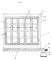
- a housing 1 surrounding the system is divided by a vertical wall of four times five filter elements 2 into a raw gas side 3 and a clean gas side 4.
- a feed channel 5 for the raw gas stream to be filtered is connected to the raw gas side 3 and a discharge channel 6 for the filtered clean gas stream is connected to the clean gas side 4.
- a cover housing 7 which can be moved in the horizontal direction.
- U-shaped and V-shaped pre-separator elements 13 and 14 are arranged on the raw gas side 3, which complete the sedimentation chambers 12.
- the sedimentation chambers 12 open at the bottom into a common collecting trough 15 into which a screw conveyor 17 driven by a motor 16 rotates. This leads the contaminants sedimented in the channel 15 via an outlet opening 18 into a collecting container 19th
Landscapes
- Chemical & Material Sciences (AREA)
- Chemical Kinetics & Catalysis (AREA)
- Filtering Of Dispersed Particles In Gases (AREA)
Claims (4)
- Installation de filtrage des impuretés présentes dans un courant de gaz au moyen d'un agencement de filtration perméable aux gaz et constitué par plusieurs éléments filtrants (2) disposés pour être traversés de manière horizontale par le courant de gaz et pour être soumis, de manière individuelle ou groupée, à l'action d'un dispositif de nettoyage pneumatique, lequel peut être déplacé dans toute la zone d'action de cet agencement de filtration, cette installation étant caractérisée par le fait que- le dispositif de nettoyage pneumatique est constitué par un carter de recouvrement (7) déplaçable sur le côté (4) de l'agencement de filtration correspondant au gaz épuré, un côté de ce carter étant constitué par au moins un élément filtrant (2),- au moins une buse (8) pouvant être alimentée en air comprimé est située à l'intérieur du carter de recouvrement (7) et peut être déplacée sur la surface du côté du carter constitué par au moins un élément filtrant (2),- des parois de séparation (10) disposées verticalement sur les éléments filtrants (2) sont situées sur le côté (3) correspondant au gaz brut, à une distance égale à la largeur du carter de recouvrement (7) déplaçable, lesquelles parois délimitent des chambres de sédimentation (12).
- Installation selon la revendication 1, caractérisée par le fait que les chambres de sédimentation (12) constituées, respectivement, par au moins un élément filtrant (2) et deux parois de séparation (10), sont complétées par des éléments de séparation avant (13, 14) reliant les parois (10) et situés à distance du plan des éléments filtrants (2).
- Installation selon l'une quelconque des revendications 1 et 2, caractérisée par le fait que les chambres de sédimentation (12) débouchent, du côté du fond, dans une goulotte d'accumulation (15) commune, dans laquelle une vis sans fin (17) s'étendant sur toute sa longueur est montée de manière rotative.
- Installation selon la revendication 3, caractérisée par le fait que la goulotte d'accumulation (15) est pourvue d'une ouverture d'évacuation (18) débouchant dans un réservoir collecteur (19).
Applications Claiming Priority (2)
| Application Number | Priority Date | Filing Date | Title |
|---|---|---|---|
| DE4234807 | 1992-10-15 | ||
| DE4234807A DE4234807A1 (de) | 1992-10-15 | 1992-10-15 | Anlage zum Ausfiltern von Verunreinigungen aus einem Gasstrom |
Publications (2)
| Publication Number | Publication Date |
|---|---|
| EP0592832A1 EP0592832A1 (fr) | 1994-04-20 |
| EP0592832B1 true EP0592832B1 (fr) | 1996-04-17 |
Family
ID=6470555
Family Applications (1)
| Application Number | Title | Priority Date | Filing Date |
|---|---|---|---|
| EP93114888A Expired - Lifetime EP0592832B1 (fr) | 1992-10-15 | 1993-09-16 | Installation de filtrage de polluants d'un courant de gaz |
Country Status (3)
| Country | Link |
|---|---|
| EP (1) | EP0592832B1 (fr) |
| AT (1) | ATE136807T1 (fr) |
| DE (2) | DE4234807A1 (fr) |
Family Cites Families (4)
| Publication number | Priority date | Publication date | Assignee | Title |
|---|---|---|---|---|
| GB1148002A (en) * | 1966-05-19 | 1969-04-10 | Simon Ltd Henry | Improvements in or relating to filters |
| DE7304079U (de) * | 1973-02-03 | 1973-08-16 | Huther & Co | Gasflaechenfilter mit einem elektrischen antriebsmotor und ventilator fuer filterreinigungsluft |
| EP0114317A3 (fr) * | 1982-12-27 | 1984-08-29 | Allis-Chalmers Corporation | Appareil de filtrage d'air |
| DE3830991A1 (de) * | 1987-09-13 | 1989-03-23 | Ltg Lufttechnische Gmbh | Filtervorrichtung und verfahren zu ihrem betreiben |
-
1992
- 1992-10-15 DE DE4234807A patent/DE4234807A1/de not_active Withdrawn
-
1993
- 1993-09-16 AT AT93114888T patent/ATE136807T1/de not_active IP Right Cessation
- 1993-09-16 DE DE59302249T patent/DE59302249D1/de not_active Expired - Fee Related
- 1993-09-16 EP EP93114888A patent/EP0592832B1/fr not_active Expired - Lifetime
Also Published As
| Publication number | Publication date |
|---|---|
| DE59302249D1 (de) | 1996-05-23 |
| EP0592832A1 (fr) | 1994-04-20 |
| ATE136807T1 (de) | 1996-05-15 |
| DE4234807A1 (de) | 1994-04-21 |
Similar Documents
| Publication | Publication Date | Title |
|---|---|---|
| DE3249102C2 (de) | Kompakstaubfilter | |
| AT408843B (de) | Staubfilter | |
| EP3730022B1 (fr) | Élément filtrant | |
| DE3422093A1 (de) | Entstaubungseinrichtung | |
| DE9212047U1 (de) | Vorrichtung zum fraktionierten Entsorgen einer Kehrmaschine | |
| DE2728137C2 (de) | Filtervorrichtung für industrielle Abwässer | |
| DE3152436C2 (fr) | ||
| EP0592832B1 (fr) | Installation de filtrage de polluants d'un courant de gaz | |
| DE69522153T2 (de) | Staubsammelapparat | |
| DE3732424C2 (fr) | ||
| AT407840B (de) | Vorrichtung zur abreinigung von schlauchfiltern | |
| DE3203112A1 (de) | Filtervorrichtung fuer die entstaubung von gasen | |
| DE2935773A1 (de) | Anlage zum filtern eines verunreinigten fliessmittels unter verwendung eines granulierten, pneumatisch wieder erneuerbaren materials | |
| WO2000026141A1 (fr) | Installation compacte pour l'epuration mecanique d'eaux usees | |
| EP3711840B1 (fr) | Installation de dépoussiérage | |
| DE3720045C2 (fr) | ||
| DE2549911A1 (de) | Staubsammeleinrichtung | |
| DE2902461A1 (de) | Vorrichtung zum reinigen von gas | |
| DE3037860A1 (de) | Gasfilter | |
| DE3445123A1 (de) | Insbesondere im bergbau einsetzbare filteranlage zur luftentstaubung | |
| DE2117088A1 (en) | Dust filtering system | |
| DE3122859A1 (de) | Filtervorrichtung fuer die entstaubung von gasen | |
| AT395294B (de) | Einrichtung mit in einem sich in seinem unteren bereich verjuengenden behaelter eingeordnetem koernigen material | |
| DE19526301C1 (de) | Muldenfilter | |
| DE2517502A1 (de) | Kiesbett-staubsammeleinrichtung |
Legal Events
| Date | Code | Title | Description |
|---|---|---|---|
| PUAI | Public reference made under article 153(3) epc to a published international application that has entered the european phase |
Free format text: ORIGINAL CODE: 0009012 |
|
| AK | Designated contracting states |
Kind code of ref document: A1 Designated state(s): AT BE CH DE DK ES FR GB GR IE IT LI LU MC NL PT SE |
|
| 17P | Request for examination filed |
Effective date: 19940328 |
|
| RAP1 | Party data changed (applicant data changed or rights of an application transferred) |
Owner name: H. KRANTZ-TKT GMBH |
|
| 17Q | First examination report despatched |
Effective date: 19950801 |
|
| GRAH | Despatch of communication of intention to grant a patent |
Free format text: ORIGINAL CODE: EPIDOS IGRA |
|
| GRAA | (expected) grant |
Free format text: ORIGINAL CODE: 0009210 |
|
| AK | Designated contracting states |
Kind code of ref document: B1 Designated state(s): AT BE CH DE DK ES FR GB GR IE IT LI LU MC NL PT SE |
|
| PG25 | Lapsed in a contracting state [announced via postgrant information from national office to epo] |
Ref country code: NL Free format text: LAPSE BECAUSE OF FAILURE TO SUBMIT A TRANSLATION OF THE DESCRIPTION OR TO PAY THE FEE WITHIN THE PRESCRIBED TIME-LIMIT Effective date: 19960417 Ref country code: IT Free format text: LAPSE BECAUSE OF FAILURE TO SUBMIT A TRANSLATION OF THE DESCRIPTION OR TO PAY THE FEE WITHIN THE PRE;WARNING: LAPSES OF ITALIAN PATENTS WITH EFFECTIVE DATE BEFORE 2007 MAY HAVE OCCURRED AT ANY TIME BEFORE 2007. THE CORRECT EFFECTIVE DATE MAY BE DIFFERENT FROM THE ONE RECORDED.SCRIBED TIME-LIMIT Effective date: 19960417 Ref country code: GR Free format text: LAPSE BECAUSE OF FAILURE TO SUBMIT A TRANSLATION OF THE DESCRIPTION OR TO PAY THE FEE WITHIN THE PRESCRIBED TIME-LIMIT Effective date: 19960417 Ref country code: ES Free format text: THE PATENT HAS BEEN ANNULLED BY A DECISION OF A NATIONAL AUTHORITY Effective date: 19960417 Ref country code: DK Effective date: 19960417 Ref country code: BE Effective date: 19960417 |
|
| REF | Corresponds to: |
Ref document number: 136807 Country of ref document: AT Date of ref document: 19960515 Kind code of ref document: T |
|
| REG | Reference to a national code |
Ref country code: IE Ref legal event code: FG4D Free format text: 68001 |
|
| REF | Corresponds to: |
Ref document number: 59302249 Country of ref document: DE Date of ref document: 19960523 |
|
| GBT | Gb: translation of ep patent filed (gb section 77(6)(a)/1977) |
Effective date: 19960530 |
|
| ET | Fr: translation filed | ||
| PG25 | Lapsed in a contracting state [announced via postgrant information from national office to epo] |
Ref country code: SE Effective date: 19960717 Ref country code: PT Effective date: 19960717 |
|
| PG25 | Lapsed in a contracting state [announced via postgrant information from national office to epo] |
Ref country code: LU Free format text: LAPSE BECAUSE OF NON-PAYMENT OF DUE FEES Effective date: 19960930 Ref country code: LI Effective date: 19960930 Ref country code: CH Effective date: 19960930 |
|
| NLV1 | Nl: lapsed or annulled due to failure to fulfill the requirements of art. 29p and 29m of the patents act | ||
| PG25 | Lapsed in a contracting state [announced via postgrant information from national office to epo] |
Ref country code: IE Free format text: LAPSE BECAUSE OF NON-PAYMENT OF DUE FEES Effective date: 19961107 |
|
| REG | Reference to a national code |
Ref country code: IE Ref legal event code: FD4D Ref document number: 68001 Country of ref document: IE |
|
| PLBE | No opposition filed within time limit |
Free format text: ORIGINAL CODE: 0009261 |
|
| PG25 | Lapsed in a contracting state [announced via postgrant information from national office to epo] |
Ref country code: MC Effective date: 19970331 |
|
| 26N | No opposition filed | ||
| REG | Reference to a national code |
Ref country code: CH Ref legal event code: PL |
|
| PGFP | Annual fee paid to national office [announced via postgrant information from national office to epo] |
Ref country code: FR Payment date: 19970702 Year of fee payment: 5 |
|
| PGFP | Annual fee paid to national office [announced via postgrant information from national office to epo] |
Ref country code: GB Payment date: 19970905 Year of fee payment: 5 |
|
| PGFP | Annual fee paid to national office [announced via postgrant information from national office to epo] |
Ref country code: DE Payment date: 19970909 Year of fee payment: 5 |
|
| PGFP | Annual fee paid to national office [announced via postgrant information from national office to epo] |
Ref country code: AT Payment date: 19970912 Year of fee payment: 5 |
|
| PG25 | Lapsed in a contracting state [announced via postgrant information from national office to epo] |
Ref country code: GB Free format text: LAPSE BECAUSE OF NON-PAYMENT OF DUE FEES Effective date: 19980916 Ref country code: AT Free format text: LAPSE BECAUSE OF NON-PAYMENT OF DUE FEES Effective date: 19980916 |
|
| GBPC | Gb: european patent ceased through non-payment of renewal fee |
Effective date: 19980916 |
|
| PG25 | Lapsed in a contracting state [announced via postgrant information from national office to epo] |
Ref country code: FR Free format text: LAPSE BECAUSE OF NON-PAYMENT OF DUE FEES Effective date: 19990531 |
|
| PG25 | Lapsed in a contracting state [announced via postgrant information from national office to epo] |
Ref country code: DE Free format text: LAPSE BECAUSE OF NON-PAYMENT OF DUE FEES Effective date: 19990701 |
|
| REG | Reference to a national code |
Ref country code: FR Ref legal event code: ST |