EP0592869B1 - Filtre - Google Patents
Filtre Download PDFInfo
- Publication number
- EP0592869B1 EP0592869B1 EP19930115718 EP93115718A EP0592869B1 EP 0592869 B1 EP0592869 B1 EP 0592869B1 EP 19930115718 EP19930115718 EP 19930115718 EP 93115718 A EP93115718 A EP 93115718A EP 0592869 B1 EP0592869 B1 EP 0592869B1
- Authority
- EP
- European Patent Office
- Prior art keywords
- lid
- connection piece
- filter
- filter according
- tank
- Prior art date
- Legal status (The legal status is an assumption and is not a legal conclusion. Google has not performed a legal analysis and makes no representation as to the accuracy of the status listed.)
- Expired - Lifetime
Links
- 238000007789 sealing Methods 0.000 claims description 2
- 239000007788 liquid Substances 0.000 description 21
- 238000010276 construction Methods 0.000 description 4
- 239000010720 hydraulic oil Substances 0.000 description 2
- 238000009423 ventilation Methods 0.000 description 2
- 230000001419 dependent effect Effects 0.000 description 1
- 239000013013 elastic material Substances 0.000 description 1
- 239000000463 material Substances 0.000 description 1
- 239000002184 metal Substances 0.000 description 1
- 239000003921 oil Substances 0.000 description 1
Images

Classifications
-
- B—PERFORMING OPERATIONS; TRANSPORTING
- B01—PHYSICAL OR CHEMICAL PROCESSES OR APPARATUS IN GENERAL
- B01D—SEPARATION
- B01D35/00—Filtering devices having features not specifically covered by groups B01D24/00 - B01D33/00, or for applications not specifically covered by groups B01D24/00 - B01D33/00; Auxiliary devices for filtration; Filter housing constructions
- B01D35/14—Safety devices specially adapted for filtration; Devices for indicating clogging
-
- B—PERFORMING OPERATIONS; TRANSPORTING
- B01—PHYSICAL OR CHEMICAL PROCESSES OR APPARATUS IN GENERAL
- B01D—SEPARATION
- B01D36/00—Filter circuits or combinations of filters with other separating devices
- B01D36/001—Filters in combination with devices for the removal of gas, air purge systems
-
- B—PERFORMING OPERATIONS; TRANSPORTING
- B01—PHYSICAL OR CHEMICAL PROCESSES OR APPARATUS IN GENERAL
- B01D—SEPARATION
- B01D2201/00—Details relating to filtering apparatus
- B01D2201/24—Tools used for the removal of filters
Definitions
- the invention relates to a filter with a connecting piece which can be screwed into a liquid container, with a cover which overlaps the connecting piece above the liquid container and with at least one filter element in the cover.
- Such filters are used, for example, as filling and ventilation filters on hydraulic oil tanks in construction machines or the like.
- the filter is screwed into a corresponding internal thread of the tank by touching its cover. Since construction machines and the like are often left unattended at construction sites at night, unauthorized persons can unscrew the filter from the tank, steal it, fill oil from the tank and contaminate the tank.
- the lid has been provided with a key, upon actuation of which the lid can be rotated freely relative to the nozzle, so that unscrewing the nozzle from the tank by touching the lid becomes impossible (Brochure: "UCC fill and ventilation filter” 1987). Furthermore, it is known in a filter of another type (DE 33 29 835 C1) to protect a screw bolt with a security element in such a way that a wrench can only be placed on the head of the screw bolt after loosening a vent screw and moving the security element.
- the object is achieved in a generic filter by the invention in that the lid is continuously connected to the nozzle endlessly freely rotatable and a contact surface for a tool is formed on the nozzle between the lid and the liquid container, with which the nozzle in the liquid container can be rotated.
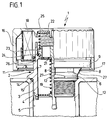
- the filter 1 shown in the drawing consists of a central filter socket 2, which is screwed by means of an external thread 3 into a corresponding internal thread 4 at the filling opening 5 of a liquid container 6, for example a hydraulic oil tank of a construction machine.
- a bayonet lock operated by rotation could also be provided.
- the nozzle 2 comprises a central tube 7, which is firmly connected via webs 8 to an annular collar 9, which in turn is provided with air inlet openings 11 directed downwards towards the liquid container 6.
- the nozzle 2 is provided on its outside immediately above the top of the liquid container 6 with four mutually parallel contact surfaces 12 for a tool 13, cf. also FIG. 2, in which a tool 13 in the form of a fork wrench is placed on two opposing contact surfaces 12. With the help of this tool 13, the nozzle 2 can be screwed firmly into the liquid container 6.
- the contact surfaces 12 are formed on an outwardly directed flange 14 of the connector 2.
- a seal 15 is inserted between the flange 14 and the liquid container 6.
- a cover 16 made of slightly elastic material is slipped over the collar 9 of the socket 2 and is snapped with a lower, radially inwardly projecting edge 17 over the lower outer edge of the collar 9 in such a way that the cover 16 is continuously rotatable endlessly with the socket 2 is connected. It is therefore not possible to screw the connection piece 2 firmly into the liquid container 6 by rotating the cover 16 or to detach the connection piece 2 screwed firmly into the container 6 from the container 6.
- the lid 16 contains in a conventional manner a paper filter element 18 folded in a star shape, e.g. is glued into the lid 16. Between nozzle 2 and cover 16, two valves are provided in a conventional manner, namely an air inlet valve 21 biased by a spring 19 and an air outlet valve 23 loaded by a spring 22.
- the air outlet valve 23 is an annular, provided with a seal 24, in the nozzle 2 axially movable block, on the underside of which the plate-shaped valve 21 abuts.
- the opening pressure of the air outlet valve 23 can be, for example, about 0.5 bar, while the opening pressure of the air inlet valve can be, for example, about -0.03 bar. If one of the valves 21 or 23 is open, air can enter or leave the liquid container 6 via the filter element 18.
- the spring 22 loading the valve 23 is supported on a washer 25 inserted into the cover 16 and made of a resistant material, for example metal.
- the spring 22 simultaneously creates a frictional connection between the socket 2 and the cover 16, so that there is a frictional connection between these two parts and the socket 2 can be loosely screwed into the liquid container 6 by touching the cover 16, at least in the course of the first rotations, until the frictional resistance of the threads 3, 4 becomes so great that for further screwing in and for tightening the socket 2 in the liquid container 6, the tool 13 mentioned must be used. Thereafter, the cover 16 can again be rotated continuously and endlessly on the nozzle 2 while overcoming the aforementioned frictional connection.
- the webs 8 provided between the annular collar 9 and the flange 14 are provided on their outside with inclined surfaces 27 which extend into the immediate vicinity of the contact surfaces 12 for the tool 13.
- the webs 8 act in this way as boundary webs and prevent wrenches of normal thickness from being applied to the contact surfaces 12.
- the open-ended wrench shown in FIG. 2 as tool 13 has a wrench size that deviates from the norm and also a wrench size that also deviates from the norm has a different thickness in order to be applied past the webs 8 to the contact surfaces 12, there is a relatively high degree of security that unauthorized persons cannot detach the nozzle 2 from the liquid container 6.
- the tool 13 need not necessarily be designed as an open-ended wrench. It is possible to provide one or more radial bores open to the outside on the flange 14, into which a rod can be inserted as a tool, with the aid of which the connection piece 2 can then be rotated in the liquid container 6.
Landscapes
- Chemical & Material Sciences (AREA)
- Chemical Kinetics & Catalysis (AREA)
- Closures For Containers (AREA)
Claims (8)
- Filtre comportant un piquage (2) agencé pour être vissé sur un réservoir (6) de fluide, un couvercle (16) qui recouvre le réservoir (6) de fluide au dessus du piquage (2) et au moins un élément de filtre (18) logé dans le couvercle (16), filtre dans lequel :- le couvercle (16) est relié constamment au piquage (2), à rotation libre sans fin, et- une surface d'appui (12), destinée à un outil (13) au moyen duquel le piquage (2) peut être vissé sur ou dévissé du réservoir (6) de fluide, est formée sur le piquage (2), entre le couvercle (16) et le réservoir (6) de fluide
- Filtre selon la revendication 1, caractérisé en ce que le piquage (2) et le couvercle (16) peuvent être assemblés l'un à l'autre par friction.
- Filtre selon la revendication 2, caractérisé en ce que la friction nécessaire est réalisée par un ressort (22) disposé entre le piquage (2) et le couvercle (16).
- Filtre selon la revendication 3, caractérisé en ce qu'une extrémité du ressort (22) s'appuie à l'intérieur du couvercle (16) sur une rondelle (25)
- Filtre selon la revendication 2, caractérisé en ce que la friction nécessaire est réalisée par un joint d'étanchéité (26) disposé entre le piquage (2) et le couvercle (16).
- Filtre selon la revendication 1, caractérisé en ce qu'au moins deux surfaces d'appui (12) qui se font face sont prévues sur le piquage (2) pour une clé à fourche.
- Filtre selon la revendication 6, caractérisé en ce que la largeur de clé de la clé à fourche n'est pas conforme à la norme.
- Filtre selon la revendication 1, caractérisé en ce que des voiles de démarcation (8), qui ne permettent d'introduire qu'un outil (13) d'épaisseur limitée, sont agencés entre le couvercle (16) et le réservoir (6) de fluide.
Applications Claiming Priority (2)
| Application Number | Priority Date | Filing Date | Title |
|---|---|---|---|
| DE19924234232 DE4234232C1 (de) | 1992-10-10 | 1992-10-10 | Filter |
| DE4234232 | 1992-10-10 |
Publications (2)
| Publication Number | Publication Date |
|---|---|
| EP0592869A1 EP0592869A1 (fr) | 1994-04-20 |
| EP0592869B1 true EP0592869B1 (fr) | 1996-12-18 |
Family
ID=6470182
Family Applications (1)
| Application Number | Title | Priority Date | Filing Date |
|---|---|---|---|
| EP19930115718 Expired - Lifetime EP0592869B1 (fr) | 1992-10-10 | 1993-09-29 | Filtre |
Country Status (2)
| Country | Link |
|---|---|
| EP (1) | EP0592869B1 (fr) |
| DE (2) | DE4234232C1 (fr) |
Cited By (1)
| Publication number | Priority date | Publication date | Assignee | Title |
|---|---|---|---|---|
| US7309367B2 (en) | 2004-04-14 | 2007-12-18 | Mann & Hummel Gmbh | Oil separator |
Families Citing this family (7)
| Publication number | Priority date | Publication date | Assignee | Title |
|---|---|---|---|---|
| DE4234232C1 (de) * | 1992-10-10 | 1994-04-28 | Argo Feinmechanik | Filter |
| DE4407177A1 (de) * | 1994-03-04 | 1995-09-07 | Knecht Filterwerke Gmbh | Öl-Tank-Belüftungsfilter |
| DE19637004A1 (de) * | 1996-09-12 | 1998-02-12 | Knecht Filterwerke Gmbh | Filter für in einen geschlossenen Behälter zurückfließende Flüssigkeit |
| DE19610457A1 (de) * | 1996-03-16 | 1997-09-18 | Pfeiffer Erich Gmbh & Co Kg | Austragvorrichtung für Medien |
| DE102005057360A1 (de) * | 2005-12-01 | 2007-06-06 | Hydac Filtertechnik Gmbh | Verschluss-System für einen Fluidbehälter, insbesondere für Hydrauliktank |
| DE102017010728A1 (de) | 2017-11-21 | 2019-05-23 | Hydac Filtertechnik Gmbh | Verschlussvorrichtung für einen Fluidbehälter |
| DE102021000062B3 (de) | 2021-01-08 | 2022-02-17 | H Y D A C Filtertechnik GmbH | Filtervorrichtung und Tankvorrichtung |
Family Cites Families (6)
| Publication number | Priority date | Publication date | Assignee | Title |
|---|---|---|---|---|
| US3224585A (en) * | 1961-08-24 | 1965-12-21 | Purolator Products Inc | Throwaway filter arrangement |
| FR1532437A (fr) * | 1967-05-24 | 1968-07-12 | Prec Mecanique Labinal | Perfectionnements apportés aux dispositifs de desserrage d'éléments filtrants et élément filtrant utilisant de tels dispositifs |
| US4465595A (en) * | 1983-08-15 | 1984-08-14 | Pall Corporation | Apparatus for assembly and dissassembly of a filter construction |
| DE3329835C1 (de) * | 1983-08-18 | 1985-04-04 | Filterwerk Mann & Hummel Gmbh, 7140 Ludwigsburg | Sicherheitsverschluß für zweiteilige Gehäuse zum Filtern von Flüssigkeiten |
| US5125428A (en) * | 1988-07-21 | 1992-06-30 | Zahnradfabrik Friedrichshafen Ag | Device for equalizing pressure between machine housing and the surroundings |
| DE4234232C1 (de) * | 1992-10-10 | 1994-04-28 | Argo Feinmechanik | Filter |
-
1992
- 1992-10-10 DE DE19924234232 patent/DE4234232C1/de not_active Expired - Lifetime
-
1993
- 1993-09-29 EP EP19930115718 patent/EP0592869B1/fr not_active Expired - Lifetime
-
1994
- 1994-04-09 DE DE4412222A patent/DE4412222C2/de not_active Expired - Lifetime
Cited By (1)
| Publication number | Priority date | Publication date | Assignee | Title |
|---|---|---|---|---|
| US7309367B2 (en) | 2004-04-14 | 2007-12-18 | Mann & Hummel Gmbh | Oil separator |
Also Published As
| Publication number | Publication date |
|---|---|
| DE4412222C2 (de) | 1996-05-15 |
| DE4234232C1 (de) | 1994-04-28 |
| EP0592869A1 (fr) | 1994-04-20 |
| DE4412222A1 (de) | 1995-10-19 |
Similar Documents
| Publication | Publication Date | Title |
|---|---|---|
| DE3249144C2 (de) | Einschraubfilter | |
| DE2600410C2 (de) | Behälter mit zugehörigem Sicherheitsverschluß | |
| EP2051890B1 (fr) | Dispositif d'alimentation en air comprimé | |
| EP2051892B1 (fr) | Dispositif d'alimentation en air comprimé pour un véhicule utilitaire et cartouche de dessiccateur | |
| DE69916063T2 (de) | Entfernbare schraubstopfen und werkzeug | |
| DE3834633A1 (de) | Kraftstoffbehaelterverschluss | |
| EP0600432B1 (fr) | Tuyauterie ou tuyauterie flexible pour le transport d'un fluide | |
| DE29807243U1 (de) | Kindersicherer und originalitätsgesicherter Behälter-Verschluß | |
| EP0369166A2 (fr) | Fermeture à vis de protection pour enfants | |
| EP0592869B1 (fr) | Filtre | |
| DE60218520T2 (de) | Nicht entfernbare vorrichtung zur befestigung einer abgabevorrichtung an einem behälter | |
| DE10007527C2 (de) | Dichtpackung zum Hindurchführen von Leitungen durch eine Wand | |
| DE2755548C2 (de) | Originalitätsverschluß mit einer zwischen zwei Teilen angeordneten Perforation | |
| EP1695867B1 (fr) | Couvercle pour le dôme d'un conteneur mobile de fuel | |
| DE3329835C1 (de) | Sicherheitsverschluß für zweiteilige Gehäuse zum Filtern von Flüssigkeiten | |
| EP0373569A2 (fr) | Récipient avec capuchon à vis muni d'un élément de garantie | |
| EP1121984B1 (fr) | Centrifugeuse avec collier de serrage comme moyen de montage | |
| DE3146647C2 (de) | Sicherung eines Verschlusses zur Verriegelung einer Abdeckung von Brunnen-, Entlüftungs- und Beobachtungsöffnungen | |
| DE19951580B4 (de) | Absperrarmatur | |
| DE8102491U1 (de) | Deckelsicherung für unter Innendruck stehende Behälter, insbesondere Schmieröl- oder Brennstoffilter | |
| EP1210540A1 (fr) | Raccord de tuyau de refoulement pour pompe | |
| DE3627238C2 (fr) | ||
| DE9402487U1 (de) | Sicherung für Muttern oder Schrauben | |
| DE102022106845A1 (de) | Anordnung mit einem Behälter und einer Originalitätssicherung | |
| DE29605374U1 (de) | Endverzweiger-Kasten |
Legal Events
| Date | Code | Title | Description |
|---|---|---|---|
| PUAI | Public reference made under article 153(3) epc to a published international application that has entered the european phase |
Free format text: ORIGINAL CODE: 0009012 |
|
| AK | Designated contracting states |
Kind code of ref document: A1 Designated state(s): FR GB IT |
|
| 17P | Request for examination filed |
Effective date: 19940712 |
|
| GRAG | Despatch of communication of intention to grant |
Free format text: ORIGINAL CODE: EPIDOS AGRA |
|
| 17Q | First examination report despatched |
Effective date: 19960322 |
|
| GRAH | Despatch of communication of intention to grant a patent |
Free format text: ORIGINAL CODE: EPIDOS IGRA |
|
| GRAH | Despatch of communication of intention to grant a patent |
Free format text: ORIGINAL CODE: EPIDOS IGRA |
|
| RAP1 | Party data changed (applicant data changed or rights of an application transferred) |
Owner name: ARGO GMBH FUER FLUIDTECHNIK |
|
| GRAA | (expected) grant |
Free format text: ORIGINAL CODE: 0009210 |
|
| ITF | It: translation for a ep patent filed | ||
| AK | Designated contracting states |
Kind code of ref document: B1 Designated state(s): FR GB IT |
|
| GBT | Gb: translation of ep patent filed (gb section 77(6)(a)/1977) |
Effective date: 19970206 |
|
| ET | Fr: translation filed | ||
| PLBE | No opposition filed within time limit |
Free format text: ORIGINAL CODE: 0009261 |
|
| STAA | Information on the status of an ep patent application or granted ep patent |
Free format text: STATUS: NO OPPOSITION FILED WITHIN TIME LIMIT |
|
| 26N | No opposition filed | ||
| PGFP | Annual fee paid to national office [announced via postgrant information from national office to epo] |
Ref country code: FR Payment date: 20000926 Year of fee payment: 8 |
|
| REG | Reference to a national code |
Ref country code: GB Ref legal event code: IF02 |
|
| PG25 | Lapsed in a contracting state [announced via postgrant information from national office to epo] |
Ref country code: FR Free format text: LAPSE BECAUSE OF NON-PAYMENT OF DUE FEES Effective date: 20020531 |
|
| REG | Reference to a national code |
Ref country code: FR Ref legal event code: ST |
|
| PGFP | Annual fee paid to national office [announced via postgrant information from national office to epo] |
Ref country code: IT Payment date: 20080821 Year of fee payment: 16 |
|
| PGFP | Annual fee paid to national office [announced via postgrant information from national office to epo] |
Ref country code: GB Payment date: 20080806 Year of fee payment: 16 |
|
| GBPC | Gb: european patent ceased through non-payment of renewal fee |
Effective date: 20090929 |
|
| PG25 | Lapsed in a contracting state [announced via postgrant information from national office to epo] |
Ref country code: GB Free format text: LAPSE BECAUSE OF NON-PAYMENT OF DUE FEES Effective date: 20090929 |
|
| PG25 | Lapsed in a contracting state [announced via postgrant information from national office to epo] |
Ref country code: IT Free format text: LAPSE BECAUSE OF NON-PAYMENT OF DUE FEES Effective date: 20090929 |