EP0592872B1 - Magnetplattenkassette - Google Patents
Magnetplattenkassette Download PDFInfo
- Publication number
- EP0592872B1 EP0592872B1 EP93115742A EP93115742A EP0592872B1 EP 0592872 B1 EP0592872 B1 EP 0592872B1 EP 93115742 A EP93115742 A EP 93115742A EP 93115742 A EP93115742 A EP 93115742A EP 0592872 B1 EP0592872 B1 EP 0592872B1
- Authority
- EP
- European Patent Office
- Prior art keywords
- center core
- surface portion
- magnetic disk
- flange
- rising edge
- Prior art date
- Legal status (The legal status is an assumption and is not a legal conclusion. Google has not performed a legal analysis and makes no representation as to the accuracy of the status listed.)
- Expired - Lifetime
Links
- 230000002093 peripheral effect Effects 0.000 claims description 23
- 230000000630 rising effect Effects 0.000 claims description 18
- 230000003247 decreasing effect Effects 0.000 claims 1
- 239000002184 metal Substances 0.000 description 6
- 238000004519 manufacturing process Methods 0.000 description 5
- 238000007796 conventional method Methods 0.000 description 2
- 239000000463 material Substances 0.000 description 2
- 238000000465 moulding Methods 0.000 description 2
- 239000000126 substance Substances 0.000 description 2
- 229920003002 synthetic resin Polymers 0.000 description 2
- 239000000057 synthetic resin Substances 0.000 description 2
- 229910000831 Steel Inorganic materials 0.000 description 1
- 239000000853 adhesive Substances 0.000 description 1
- 230000001070 adhesive effect Effects 0.000 description 1
- 230000000694 effects Effects 0.000 description 1
- 238000003754 machining Methods 0.000 description 1
- 238000004080 punching Methods 0.000 description 1
- 229920005989 resin Polymers 0.000 description 1
- 239000011347 resin Substances 0.000 description 1
- 239000010959 steel Substances 0.000 description 1
Images
Classifications
-
- G—PHYSICS
- G11—INFORMATION STORAGE
- G11B—INFORMATION STORAGE BASED ON RELATIVE MOVEMENT BETWEEN RECORD CARRIER AND TRANSDUCER
- G11B23/00—Record carriers not specific to the method of recording or reproducing; Accessories, e.g. containers, specially adapted for co-operation with the recording or reproducing apparatus ; Intermediate mediums; Apparatus or processes specially adapted for their manufacture
- G11B23/02—Containers; Storing means both adapted to cooperate with the recording or reproducing means
- G11B23/03—Containers for flat record carriers
- G11B23/0301—Details
- G11B23/0312—Driving features
-
- G—PHYSICS
- G11—INFORMATION STORAGE
- G11B—INFORMATION STORAGE BASED ON RELATIVE MOVEMENT BETWEEN RECORD CARRIER AND TRANSDUCER
- G11B23/00—Record carriers not specific to the method of recording or reproducing; Accessories, e.g. containers, specially adapted for co-operation with the recording or reproducing apparatus ; Intermediate mediums; Apparatus or processes specially adapted for their manufacture
- G11B23/0014—Record carriers not specific to the method of recording or reproducing; Accessories, e.g. containers, specially adapted for co-operation with the recording or reproducing apparatus ; Intermediate mediums; Apparatus or processes specially adapted for their manufacture record carriers not specifically of filamentary or web form
- G11B23/0021—Record carriers not specific to the method of recording or reproducing; Accessories, e.g. containers, specially adapted for co-operation with the recording or reproducing apparatus ; Intermediate mediums; Apparatus or processes specially adapted for their manufacture record carriers not specifically of filamentary or web form discs
- G11B23/0028—Details
- G11B23/0035—Details means incorporated in the disc, e.g. hub, to enable its guiding, loading or driving
Definitions
- the present invention relates to a magnetic disk cartridge and, more particularly, to a magnetic disk cartridge according to the preamble of claim 1.
- the magnetic disk 1 is rotatably received in a cartridge case (not shown).
- the center core 2 is formed of a metal plate (a magnetic substance) having relatively good malleability.
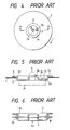
- Fig. 5 which is an enlarged section view taken along a line A - A in Fig. 4
- the center core 2 includes a flange 2c provided in the outer peripheral portion thereof and two engagement holes 2a, 2b formed by drawing.
- the flange 2c is used to fix the core 2 to the magnetic disk 1 by means of an adhesive member 3 such as a double-sided tape or the like.
- a drive shaft D is inserted into one of the two engagement holes, namely, the engagement hole 2a (a cylindrical hole having a burred edge portion), which is formed in the center of the center core 2, while a positioning pin P is inserted into the other engagement hole 2b.
- the engagement hole 2a a cylindrical hole having a burred edge portion
- the flange 2c includes an inner peripheral corner portion 2d, while the center core 2 includes a bottom outer peripheral corner portion 2e. Due to the drawing machining process used to form them, the two corner portions 2d and 2d have a certain curvature.
- the drawn center core 2 can be stored and held in various conditions; for example, a large number of center cores are often stored in a case or the like before they are delivered for assembly with magnetic discs, or the center cores are stored in a hopper or the like forming a center core supply device provided in an automatic assembly facility.
- the center cores 2 are sometimes stacked on each other.
- the center cores 2 for example, as shown in Fig. 6, there occurs a condition wherein, with the centers of the center cores coincident with each other, the center cores are vertically superimposed on each other.
- the inner peripheral corner portion 2d and the bottom outer peripheral corner portion 2e can bite into each other due to manufacturing tolerances in the dimensions of the cores 2.
- the center core delivery line may be stopped or other problems occur. In such an instance, such center cores 2 must be taken away from the delivery line and detached from each other by hand, then sent back again to the delivery line. This requires extra labor and time.
- a center core is employed in which the metal plate of the center core is inserted into a synthetic resin member to thereby form the flange portion of the core plate as a resin portion, and the bottom surface (chucking surface) of the center core is made larger than the inner periphery of the flange, thereby to avoid the above-mentioned biting phenomenon.
- a further magnetic disk cartridge of the above kind comprising a center core and a magnetic sheet is presented by the Japanese document JP 62-114 179A which, however, rises the same problems during the manufacturing process.
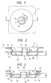
- FIG. 1 is a general plan view of the cartridge, showing a state thereof in which a magnetic disk is disposed within a cassette shell S
- Fig. 2 is an enlarged section view taken along a line A - A in Fig. 1.
- parts which are the same as the conventional ones shown in Figs. 4 to 6 are given the same respective designations, and a further detailed description thereof is omitted.
- a disk-shaped magnetic disk sheet 1 which includes a magnetic recording layer on a macromolecular film, is fixedly secured to the lower surface of a flange portion 2c of a center core 2 formed of a metal plate (a magnetic substance) by means of a double-sided tape 3 (see Fig. 5), and is assembled integrally with the center core 2, thereby forming a magnetic disk.
- the magnetic disk is rotatably received in the cassette shell S, with the bottom surface portion 4b of the center core exposed.
- the center core 2 includes a circular recessed portion 4 formed by punching and drawing a metal plate (formed of a steel material such as SuS430, SuS431, DP1 or the like) having a high malleability.
- the center core 2 includes within the circular recessed portion 4 an elongated hole 2b into which a positioning pin P is to be inserted and an engagement hole 2a into which a drive shaft D is to be inserted.
- the above-mentioned flange portion 2c of the center core 2 is formed on the outer periphery of the circular recessed portion 4.
- a rising edge portion 2h at the edge portion of the engagement hole 2a is formed by burring simultaneously with the drawing operation in such a manner that the rising edge portion 2h has a square section.
- the engagement hole 2a as shown in Fig. 1, is formed in such a manner that the center line thereof intersects the longitudinal center line of the elongated hole 2b at a certain angle. The reason for this is that when the bottom surface of the center core 2 or a chucking surface 2g is attracted by a magnetic M as shown in Fig. 5 and the magnetic disk is rotated, the drive shaft D and the pin P are pressed against the respective hole wall surfaces due to the centrifugal force of the magnetic disk and are thus kept at their respective contact positions, thereby to maintain constant the center of rotation of the magnetic disk.
- the rising edge portion 2h of the center core 2 extends a height Ha in the direction of an imaginary plane B including the flange portion 2c. That is, the rising edge portion 2h is relatively higher than the corresponding portion in a conventional center core. Due to this feature, when two or more center cores are stacked together as shown in Fig. 2, the leading end 2i of the rising edge portion 2h of the lower center core contacts the outer surface of the circular recessed portion 4 of the upper center core 2 before the inner peripheral corner portion 2d of the flange portion 2c can contact the bottom outer peripheral portion 2e of the circular recessed portion 4.
- the height of the rising edge portion 2h is lower than that shown in Fig. 2, while the radius of curvature r 2 of the bottom outer peripheral corner portion 2e of the center core 2 is made greater than the radius of curvature r 1 of the inner peripheral corner portion 2d of the flange.
- the radius of curvature r 2 of the bottom outer peripheral corner portion 2e is greater than the radius of curvature r. of the inner peripheral corner portion 2d, a portion extending between the side surface portion 4a and the bottom surface portion 4b of the circular recessed portion 4 provides a smoothly inclined structure.
- disc cartridges were produced in which the radius of curvature r 2 was greater than the radius of curvature r 1 .
- the total height Ht of the center core 2 was 1.70 to 1.80 mm and the height of the rising edge portion 2a was 1.20 mm or less (for example, 1.15 to 1.00 mm)
- the height of the rising edge portion is determined such that, when the center cores are stacked together facing in the same direction, the rising edge portion end face of one center core is first contacts the bottom portion of the other center core, the center cores are prevented from biting into each other.
- no inconvenience can occur in a magnetic disk assembly line, so that the productivity of the magnetic disk cartridges can be enhanced.
Landscapes
- Holding Or Fastening Of Disk On Rotational Shaft (AREA)
Claims (3)
- Magnetscheibenkassette, die einen Mittelkern (2) enthält, mit:wobei die Antriebswellen- Eingriffsöffnung (2a) durch einen ansteigenden Kantenabschnitt (2h) gebildet ist, der sich von dem Bodenoberflächenabschnitt (4b) in die Richtung zu dem Oberseiteabschnitt des Flansches (2c) erstreckt,einem äußeren Umfangsflansch (2c) zum Befestigen einer Magnetscheibenplatte (1) und zum Bilden eines Oberseitenabschnittes des Mittelkerns (2),einer Antriebswellen- Eingriffsöffnung (2a), gebildet in dem Mittelabschnitt des Mittelkerns (2),einem kreisförmig ausgesparten Abschnitt (4), gebildet durch Ziehen eines Innenabschnittes des Flansches in eine Richtung mit einem Niveauunterschied, mit einem Bodenoberflächenabschnitt (4b) und der radial zwischen dem Flansch (2c) und der Antriebswellen- Eingriffsöffnung (2a) gebildet ist,
wobei die Höhe (Ha) des ansteigenden Kantenabschnittes (2h) kleiner als die Gesamthöhe (Ht) des Mittelkems (2) ist, die durch den Abstand des oberen Oberflächenabschnittes von dem Bodenoberflächenabschnitt (4b) gebildet ist,
dadurch gekennzeichnet, dass
die minimale Höhe (Ha) des ansteigenden Kantenabschnittes (2h) auf einen Wert gesetzt ist, der es einem oberen vorauslaufenden Ende (2i) des ansteigenden Kantenabschnittes (2h) eines unteren Mittelkerns (2) gestattet, den Bodenoberflächenabschnitt (4b) eines oberen Mittelkerns (2) zu berühren, wenn die Mittelkerne (2), welche dieselbe Form haben, übereinander gestapelt sind, während dadurch zwischen einem äußeren Umfangseckabschnitt (2e), der einen Seitenoberflächenabschnitt (4a) mit dem kreisförmig ausgesparten Abschnitt (4a) des oberen Mittelkems (2) verbindet, und einem inneren Umfangseckabschnitt (2d), der den Seitenoberflächenabschnitt (4a) mit dem Flansch (2c) des unteren Mittelkerns (2) verbindet, ein Abstand belassen wird. - Magnetscheibenkassette nach Anspruch 1, dadurch gekennzeichnet, dass der Seitenoberflächenabschnitt (4a), der den kreisförmig ausgesparten Abschnitt (4) mit dem Flanschabschnitt (2c) verbindet, in einer konischen Form gebildet ist, wobei dessen Durchmesser sich von dem Oberseitenabschnitt des Flansches (2c) in die Richtung zu dem Bodenoberflächenabschnitt (4b) des kreisförmig ausgesparten Abschnittes (4) vermindert.
- Magnetscheibenkassette nach Anspruch 1 oder 2, dadurch gekennzeichnet, dass die Gesamthöhe (Ht) des Mittelkems (2) in einem Bereich von 1,70 bis 1,80 mm ist, ein Krümmungsradius (r1) des inneren Umfangseckabschnittes (2d) ungefähr 0,6 mm ist, ein Krümmungsradius (r2) des äußeren Umfangseckabschnittes (2e) in dem Bereich von 0,6 bis 0,9 mm ist, und die Höhe des ansteigenden Eckabschnittes (2h) in einem Bereich von 1,20 bis 1,40 mm ist.
Applications Claiming Priority (3)
| Application Number | Priority Date | Filing Date | Title |
|---|---|---|---|
| JP7717492U | 1992-10-13 | ||
| JP77174/92U | 1992-10-13 | ||
| JP077174U JPH0638068U (ja) | 1992-10-13 | 1992-10-13 | 磁気ディスクカートリッジ |
Publications (3)
| Publication Number | Publication Date |
|---|---|
| EP0592872A2 EP0592872A2 (de) | 1994-04-20 |
| EP0592872A3 EP0592872A3 (de) | 1995-02-15 |
| EP0592872B1 true EP0592872B1 (de) | 2004-11-24 |
Family
ID=13626439
Family Applications (1)
| Application Number | Title | Priority Date | Filing Date |
|---|---|---|---|
| EP93115742A Expired - Lifetime EP0592872B1 (de) | 1992-10-13 | 1993-09-29 | Magnetplattenkassette |
Country Status (4)
| Country | Link |
|---|---|
| US (1) | US5453898A (de) |
| EP (1) | EP0592872B1 (de) |
| JP (1) | JPH0638068U (de) |
| DE (1) | DE69333707T2 (de) |
Families Citing this family (6)
| Publication number | Priority date | Publication date | Assignee | Title |
|---|---|---|---|---|
| US5539599A (en) * | 1994-08-01 | 1996-07-23 | Blue Ridge Group, L.L.C. | Fastener for flexible disk cartridges |
| US5896241A (en) * | 1996-08-07 | 1999-04-20 | Imation Corp. | Plain carbon steel hub for data storage device |
| US6134081A (en) | 1997-08-29 | 2000-10-17 | Iomega Corporation | Media hub mounting system for minimizing Z-axis during cartridge insertion and ejection translation |
| US5999382A (en) * | 1997-08-29 | 1999-12-07 | Iomega Corporation | Apparatus for restraining lateral movement of disk medium within a cartridge shell |
| US6205113B1 (en) | 1998-08-18 | 2001-03-20 | Iomega Corporation | Plastic clamp with hub and platter for use in disc drive |
| JP4313739B2 (ja) * | 2004-08-19 | 2009-08-12 | 富士フイルム株式会社 | 記録ディスクカートリッジ |
Family Cites Families (7)
| Publication number | Priority date | Publication date | Assignee | Title |
|---|---|---|---|---|
| JPS56154627A (en) * | 1980-05-02 | 1981-11-30 | Chugoku Electric Power Co Ltd:The | Detector for loose part |
| JPS60147962A (ja) * | 1984-01-10 | 1985-08-05 | Toshiba Corp | フロツピ−デイスク装置 |
| JPS60164953A (ja) * | 1984-02-06 | 1985-08-28 | Sony Corp | デイスクの回転駆動装置 |
| JPH077587B2 (ja) * | 1985-11-13 | 1995-01-30 | ソニー株式会社 | フロツピ−デイスクの加工方法 |
| JPS6417277A (en) * | 1987-07-11 | 1989-01-20 | Hitachi Maxell | Discoid recording medium |
| JP2537348Y2 (ja) * | 1988-01-19 | 1997-05-28 | 三井石油化学工業株式会社 | 光ディスク |
| JPH03295083A (ja) * | 1990-04-13 | 1991-12-26 | Seiko Epson Corp | 単板型光ディスク |
-
1992
- 1992-10-13 JP JP077174U patent/JPH0638068U/ja active Pending
-
1993
- 1993-09-29 DE DE69333707T patent/DE69333707T2/de not_active Expired - Lifetime
- 1993-09-29 EP EP93115742A patent/EP0592872B1/de not_active Expired - Lifetime
- 1993-10-06 US US08/132,672 patent/US5453898A/en not_active Expired - Lifetime
Also Published As
| Publication number | Publication date |
|---|---|
| EP0592872A2 (de) | 1994-04-20 |
| DE69333707T2 (de) | 2005-04-14 |
| EP0592872A3 (de) | 1995-02-15 |
| DE69333707D1 (de) | 2004-12-30 |
| JPH0638068U (ja) | 1994-05-20 |
| US5453898A (en) | 1995-09-26 |
Similar Documents
| Publication | Publication Date | Title |
|---|---|---|
| EP0278358B1 (de) | Platte für Aufzeichnungs- und/oder Wiedergabegerät mit magnetischer Klemmvorrichtung | |
| EP0116471A1 (de) | Flexible Magnetscheiben | |
| EP0284687A2 (de) | Bandkassette | |
| US7540005B2 (en) | Disk drive | |
| US4743994A (en) | Arrangement for positioning a recording disc of a disc cartridge | |
| EP0592872B1 (de) | Magnetplattenkassette | |
| US6049522A (en) | Laminated optical disc and turntable for the laminated optical disc | |
| EP0240237B1 (de) | Plattenklemmvorrichtung | |
| US7307813B1 (en) | Apparatuses and methods for improving disk pack balancing in disk drives including methods for centering disk clamps | |
| EP0216708A2 (de) | Plattenkassette | |
| JP2508066Y2 (ja) | 磁気ディスクカ―トリッジ | |
| US6307713B1 (en) | Center core for disc-shaped recording medium and process of producing same | |
| US20090001844A1 (en) | Motor adopting improved mechanism | |
| US20050071862A1 (en) | Disk device having clamp mechanism | |
| US20020181152A1 (en) | Magnetic tape cartridge | |
| EP0284162B1 (de) | Plattentellervorrichtung für eine Informationsplatte | |
| EP0226378B1 (de) | Datenspeicherplattengerät | |
| EP0246298B1 (de) | Antriebsmechanismus für speicherplatte und nabe | |
| US4774609A (en) | Device for a flexible magnetic disk | |
| JPH0216456Y2 (de) | ||
| KR0140883B1 (ko) | 자기 디스크의 센터코어 | |
| JP2003203410A (ja) | ディスククランプ機構 | |
| US4774619A (en) | Magnetic disk cartridge with an improved center core | |
| EP1267351A3 (de) | Plattenkassette | |
| JP2001035115A (ja) | 磁気ディスク用センタコア |
Legal Events
| Date | Code | Title | Description |
|---|---|---|---|
| PUAI | Public reference made under article 153(3) epc to a published international application that has entered the european phase |
Free format text: ORIGINAL CODE: 0009012 |
|
| AK | Designated contracting states |
Kind code of ref document: A2 Designated state(s): DE FR |
|
| PUAL | Search report despatched |
Free format text: ORIGINAL CODE: 0009013 |
|
| AK | Designated contracting states |
Kind code of ref document: A3 Designated state(s): DE FR |
|
| 17P | Request for examination filed |
Effective date: 19950309 |
|
| 17Q | First examination report despatched |
Effective date: 19990224 |
|
| GRAP | Despatch of communication of intention to grant a patent |
Free format text: ORIGINAL CODE: EPIDOSNIGR1 |
|
| GRAS | Grant fee paid |
Free format text: ORIGINAL CODE: EPIDOSNIGR3 |
|
| GRAA | (expected) grant |
Free format text: ORIGINAL CODE: 0009210 |
|
| AK | Designated contracting states |
Kind code of ref document: B1 Designated state(s): DE FR |
|
| REF | Corresponds to: |
Ref document number: 69333707 Country of ref document: DE Date of ref document: 20041230 Kind code of ref document: P |
|
| PLBE | No opposition filed within time limit |
Free format text: ORIGINAL CODE: 0009261 |
|
| STAA | Information on the status of an ep patent application or granted ep patent |
Free format text: STATUS: NO OPPOSITION FILED WITHIN TIME LIMIT |
|
| ET | Fr: translation filed | ||
| 26N | No opposition filed |
Effective date: 20050825 |
|
| REG | Reference to a national code |
Ref country code: FR Ref legal event code: TP Ref country code: FR Ref legal event code: CD |
|
| PGFP | Annual fee paid to national office [announced via postgrant information from national office to epo] |
Ref country code: DE Payment date: 20110831 Year of fee payment: 19 Ref country code: FR Payment date: 20110922 Year of fee payment: 19 |
|
| REG | Reference to a national code |
Ref country code: FR Ref legal event code: ST Effective date: 20130531 |
|
| REG | Reference to a national code |
Ref country code: DE Ref legal event code: R119 Ref document number: 69333707 Country of ref document: DE Effective date: 20130403 |
|
| PG25 | Lapsed in a contracting state [announced via postgrant information from national office to epo] |
Ref country code: DE Free format text: LAPSE BECAUSE OF NON-PAYMENT OF DUE FEES Effective date: 20130403 |
|
| PG25 | Lapsed in a contracting state [announced via postgrant information from national office to epo] |
Ref country code: FR Free format text: LAPSE BECAUSE OF NON-PAYMENT OF DUE FEES Effective date: 20121001 |