EP0592918A1 - Dispositif de transport avec un cordon de maillons - Google Patents
Dispositif de transport avec un cordon de maillons Download PDFInfo
- Publication number
- EP0592918A1 EP0592918A1 EP93116031A EP93116031A EP0592918A1 EP 0592918 A1 EP0592918 A1 EP 0592918A1 EP 93116031 A EP93116031 A EP 93116031A EP 93116031 A EP93116031 A EP 93116031A EP 0592918 A1 EP0592918 A1 EP 0592918A1
- Authority
- EP
- European Patent Office
- Prior art keywords
- link
- metal piece
- plastic
- plastic part
- links
- Prior art date
- Legal status (The legal status is an assumption and is not a legal conclusion. Google has not performed a legal analysis and makes no representation as to the accuracy of the status listed.)
- Granted
Links
- 239000004033 plastic Substances 0.000 claims abstract description 74
- 229920003023 plastic Polymers 0.000 claims abstract description 74
- 229910052751 metal Inorganic materials 0.000 claims abstract description 73
- 239000002184 metal Substances 0.000 claims abstract description 73
- 239000000969 carrier Substances 0.000 claims description 5
- 229910001220 stainless steel Inorganic materials 0.000 claims description 4
- 239000010935 stainless steel Substances 0.000 claims description 4
- 238000010438 heat treatment Methods 0.000 abstract description 5
- 238000004140 cleaning Methods 0.000 abstract description 2
- 239000000463 material Substances 0.000 description 10
- 230000000694 effects Effects 0.000 description 3
- 230000002349 favourable effect Effects 0.000 description 3
- 235000013305 food Nutrition 0.000 description 3
- 238000004806 packaging method and process Methods 0.000 description 3
- 239000012459 cleaning agent Substances 0.000 description 2
- 239000007788 liquid Substances 0.000 description 2
- 125000006850 spacer group Chemical group 0.000 description 2
- 229910001369 Brass Inorganic materials 0.000 description 1
- 238000005299 abrasion Methods 0.000 description 1
- 229910052782 aluminium Inorganic materials 0.000 description 1
- XAGFODPZIPBFFR-UHFFFAOYSA-N aluminium Chemical compound [Al] XAGFODPZIPBFFR-UHFFFAOYSA-N 0.000 description 1
- 239000011324 bead Substances 0.000 description 1
- 239000010951 brass Substances 0.000 description 1
- 238000009826 distribution Methods 0.000 description 1
- 230000003670 easy-to-clean Effects 0.000 description 1
- 235000021056 liquid food Nutrition 0.000 description 1
- 238000005461 lubrication Methods 0.000 description 1
- 238000004519 manufacturing process Methods 0.000 description 1
Images



Classifications
-
- B—PERFORMING OPERATIONS; TRANSPORTING
- B65—CONVEYING; PACKING; STORING; HANDLING THIN OR FILAMENTARY MATERIAL
- B65G—TRANSPORT OR STORAGE DEVICES, e.g. CONVEYORS FOR LOADING OR TIPPING, SHOP CONVEYOR SYSTEMS OR PNEUMATIC TUBE CONVEYORS
- B65G35/00—Mechanical conveyors not otherwise provided for
- B65G35/08—Mechanical conveyors not otherwise provided for comprising trains of unconnected load-carriers, e.g. belt sections, movable in a path, e.g. a closed path, adapted to contact each other and to be propelled by means arranged to engage each load-carrier in turn
Definitions
- the invention relates to a conveyor device with a strand of links which are driven against one another by end faces and are held by means of guide rails, on the opposite sides of which grooves are arranged in the longitudinal direction of the transport for receiving guide and drive means, with a bore for the receiving of a driving pin Cross direction.
- the coefficient of thermal expansion of the plastic which is suitable for such chain links, is relatively large. It is also not possible to use other plastics with a lower coefficient of thermal expansion.
- the purpose of the known conveyor device is also to drive the strand of the links close to one another and thus rubbing them against the respective end faces of the links, e.g. by a linear actuator. If, however, the strand is endless, the links can also be driven at one point by pulling, because this pulling force is then converted into a pushing force. In any case, friction between the links and guides is inevitable. This friction is a first source of heat, which in some cases leads to undesirable heating of the limb.
- the heat from the environment also acts on the individual links from the inside, with the consequence of a not inconsiderable heating.
- temperatures of up to 60 ° C were measured for a strand member, and the heat was hardly dissipated in this extreme application of the conveyor in the hygiene area of a very powerful machine, because the known conveyor worked there in an enclosed space.
- the invention is therefore based on the object of providing a link for a conveying device in which, in addition to an exact guidance of conveyed workpieces, precise positioning under individual processing stations and easy cleaning of the links, the heating has no disadvantageous consequences even in rough operation and under extreme conditions .
- the aim was, among other things, to create a link similar to that of the known conveyor, but which has a much lower thermal expansion. It should be noted here that the use of a different material to avoid the disadvantageous linear expansion is not readily possible. Due to compliance with the hygiene requirements, sliding parts had to be provided on metal rails, and the friction conditions could not be changed significantly.
- the solution to the problem had to be found in the context of a material combination of plastic and stainless metal, because on the one hand the operating conditions for liquid foodstuffs have to be met and on the other hand the cleaning agents have to be compatible with the materials.
- a metal piece extending in the longitudinal direction of transport is fastened to the member having at least a first plastic part in such a way that the end face of the at least one first plastic part is over the metal piece protrudes in the longitudinal direction of transport, and that the total length of the link is greater than the total length of the metal piece.
- a metal piece is inserted lengthways in each link of the strand, which is 5 to 30%, preferably 10 to 20%, shorter than the total length of the link. A large part of the link is thus taken up by the metal piece, so that the thermal expansion with respect to this length component is only relevant for the metal piece.
- the metal piece expands much less than the plastic, the feared length expansion is significantly reduced. Only a small remaining part of, for example, 5 to 10% of the total length of the link is made of plastic. Despite the higher coefficient of thermal expansion of the plastic, an increase in the temperature of the entire member has only a slight increase in length. At the same time, it can be achieved that at least one end face of the link consists of plastic, so that either two plastic surfaces or at most one end of the metal piece rub against one another with a plastic surface.
- the plastic namely allows a lubrication-free movement of the links of the conveyor relative to each other. This enables the desired precise positioning under the individual processing stations, the workpieces attached to one link can be guided exactly, and the entire conveyor device is nevertheless very easy to clean.
- the metal piece extends in the longitudinal direction through the Plastic part of the link extending push pin, one end of which protrudes outwards by an amount beyond the first end face of the plastic part and the other end of which rests against an abutment surface which is fitted in the plastic part and runs in the transverse direction of the link and which is at a distance from the second end face is small compared to the length of the metal piece.
- one end of the push pin rubs against the plastic end face of the adjacent link, and this pair of materials is found along the entire length of the conveyor.
- the total length of the link which is essential for the proper functioning of the conveying device, can be determined precisely and precisely, because the stop surface is provided in a precisely determinable and predetermined location in the plastic part. This lies at a precise distance from the second end face, so that the total length of the link is fixed. Nevertheless, the total length is divided with respect to the material so that the push pin extends over most of the longitudinal direction of transport with the small coefficient of thermal expansion, while only the smallest part of the longitudinal direction of the link is taken up by the plastic. In the case of stainless steel, the push pin only expands by 1/10 as much as the plastic. As a result, the total expansion of the link of the conveyor device according to the invention is considerably reduced even when the temperature rises.
- the portion of the length which is still made of plastic and which has an effect on the expansion that is to say only the part which is to be added to the length of the push pin, is kept as short as possible, for example 5 or 10% of the total length of the link; as short as the link's mechanical stability allows.
- the link of the conveying strand has at least two spaced-apart plastic parts, each with end faces projecting outward beyond the metal piece, and in that the plastic parts are connected to one another by the metal piece.
- the major part of the thermal expansion of the plastic segments can be shifted inwards.
- the interior is free and does not determine the precise overall length of the link.
- plastic end faces protruding from both ends of the link so that plastic rubs against plastic when the links are in the conveyor train and move. This almost completely prevents any abrasion points.
- the metal piece connecting the two plastic parts can be in the middle, but in a particularly preferred embodiment is attached on the outside on each side.
- each link has two pieces of metal fastened to the side cheeks of the plastic parts in the form of webs, tabs or rails, to which preferably workpiece carriers are attached in a non-detachable manner. It is expedient if the fastening points of the metal pieces on the plastic parts are spaced far apart or are provided on the outside in the end region of the link. This allows a favorable distribution in terms of thermal expansion to be selected, namely transferring the main part of the thermal expansion to the metal piece and leaving only the remainder of 5% or more in the plastic part, because this protrudes outwards and forms the lubrication-free end face as a friction surface.
- a web is addressed in connection with the metal piece, then it is meant an elongated shape from one end region of the link to the opposite.
- Such webs can only consist of an elongated rod, but the webs can also have the shape of a double-T web in order to provide the main part of the web over the main longitudinal direction of transport of the link and preferably in the area of its end to have small transverse webs in order to have one to ensure good security against rotation. This allows the plastic parts to be fixed in the right place (outside) and secured against rotation with the two metal pieces on the side panels.
- a tab or rail is mentioned in connection with the metal piece.
- This can be plate-like structures, which are preferably even reinforced with beads.
- the metal pieces attached to the side cheeks are connecting pieces in the above sense, because they connect two plastic parts arranged at a distance from one another.
- these metal pieces can also be used as a holder for workpiece carriers. The latter can either be connected to the plastic parts by attaching the metal pieces or separately to the workpiece carriers.
- the metal pieces are made of stainless steel and the plastic is preferably UHMW-PE (DIN 7728).
- UHMW-PE UHMW-PE
- the plastic is well compatible with the cleaning agents customary in the food industry.
- it has the desired mechanical properties, ie a plastic part made of such a material is rigid and dimensionally stable, the outer surfaces, in particular the end faces in this case, being able to slide on one another without lubrication.
- the metal pieces or tabs can of course also be shaped like an angle, in order then to be able to fasten the workpiece carriers even more easily to the links.
- Stainless steel is chosen because it meets all requirements related to hygiene in food packaging and expands much less than e.g. Brass or aluminum.
- the web-like pieces of metal are preferably inserted to prevent rotation, also in correspondingly provided grooves in the plastic part in question.
- the tab-shaped metal pieces have stiffening ribs and if anti-rotation devices are provided between the metal pieces and the plastic parts, e.g. Bolts, clamping screws, T-profiles in such a way that a piece of metal is to be fastened in a torsion-proof manner to the plastic part.
- the distance e.g. two connecting bolts from each other in the longitudinal direction of transport, with the aid of which the tab-like metal pieces are connected to the plastic parts, is preferably chosen to be as long as possible in order to transfer the proportion of thermal expansion to the metal pieces as much as possible. Only enough material must remain in the respective plastic part towards the end face to the outside that perfect strength and functional reliability remain guaranteed. At a distance transversely to such connecting bolts, small anti-rotation bolts can be introduced downwards and upwards, which extend a little from the outside to the inside of the tab-like metal pieces into the plastic parts.
- the distance from the outer end of the connecting bolt to the adjacent end face can only be approximately 5 mm.
- This embodiment then has a share of 2.5% on each side.
- the plastic material contributes to the expansion, while the 95% is taken over by the metal piece with the correspondingly low thermal expansion.
- the longitudinal direction of transport is shown for all embodiments only in FIG. 1 as an arrow pointing to the left and designated 1, although the conveyor could also be moved in the opposite direction, so that the arrow should also point to the right. However, the direction of transport remains in line 1.
- the transverse direction is shown in FIG. 2 with an arrow 2 pointing to the right, the transverse direction also being able to be assumed here in the opposite direction, in any case the transverse direction also remains in the Line 2.
- the link of the first embodiment according to FIGS. 1 and 2 has the shape of a cuboid, which is longer in the longitudinal direction of transport 1 than in the transverse direction 2.
- the strand of links not shown, extends horizontally in the longitudinal direction 1, the transverse direction 2 is then assumed to be horizontal for the sake of simplicity.
- the length L of the link is, for example, 200 mm. Its width is 70 mm as well as its height.
- a bore 5 runs through the link in the transverse direction 2 approximately at half the height such that the Bore 5 also extends through a lower recess 6 extending in the longitudinal direction of transport 1.
- this is located on the inner side facing the deflection wheels (also not shown).
- the teeth of deflection wheels can be received in the recess.
- the link With the aid of its recess 6, the link also engages in a curved end region of the conveyor device via deflection wheels.
- a drive bolt, not shown, is fixed in the bore 5. The teeth on the circumference of a drive wheel can thus ensure the movement of the link in the conveyor. Because one link sits directly behind the other, the driven link pushes the links in front in the direction of transport 1 with a sliding effect, so that no extension of the strand has to be feared even when high shear forces are introduced.
- the above-described upper groove 3 is used for sliding engagement of a curved guide rail holding the link in the strand from the outside, which is also not shown here.
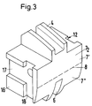
- each link is provided with an end face 7, which is a flat surface 7 'above a dashed line 8 shown in FIGS. 3 and 7, while a curved surface 7' 'adjoins the straight line 8.
- end face 7 is a flat surface 7 'above a dashed line 8 shown in FIGS. 3 and 7, while a curved surface 7' 'adjoins the straight line 8.
- one link pushes the next one over the flat end face 7 ', and in the easily imaginable but not shown curved sections, the mutual pushing takes place along a line contact between the curved end faces 7' '.
- auxiliary bag bores 11 at a distance in the longitudinal transport direction 1 in order to fix the link in operation against rotation about an axis, which e.g. runs in the transverse direction 2 through the axis of the bore 5.
- the total length of the respective link of all embodiments is designated by L in FIG.
- this is composed of the length l of the shear pin-like metal piece 10 + the distance d.
- the first end face 7 1 shown on the left in the figures is in the embodiment of Figures 1 and 2 behind the one, left end of the metal piece 10 by a distance b back with the result that in the arrangement of the links one behind the other one end 9 of the metal piece 10 bears against the second end face 72 of the next link, not shown, and thereby causes the thrust drive.
- a push pin-like metal piece 10 always rubs over its one end 9 with an end face 7 2 of the next plastic part 12 made of the plastic mentioned at the beginning.
- the distance d is formed in that a transverse groove 14 is introduced in the transverse direction 2 from one side to the other in such a way that a flat stop surface 15 results on the right-hand end face 72, against which said other end 13 of the shear pin-shaped metal piece 10 comes in plant. So that this right end 13 of the metal piece 10 is exactly at a distance d from the second end face 72 of the plastic part 12.
- the bolt-shaped metal piece 10 is also arranged in the longitudinal direction of transport 1 as the distance d between the relevant right end of the metal piece 10 and the second end face 72 is measured.
- the projection b of one end 9 of the metal piece 10 on the side shown in FIG. 1 can be very small, e.g. only be 10% of the distance d.
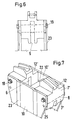
- each link has at least two plastic parts 12 and 12 'which are arranged at a distance B (FIG. 9, clear width) from one another. According to the representation of the third exemplary embodiment according to FIGS. 6 to 9, these are connected to one another by two tab-like metal pieces 10, 10 '. These metal pieces 10, 10 'are attached to the outer side walls 16 of the plastic parts 12, 12'.
- FIGS. 3 to 5 one can again see the grooves 3 (top) and 6 (bottom), which extend on opposite sides in the longitudinal direction of transport 1.
- a longitudinal groove 17 extending in the longitudinal direction of transport 1 and a vertical groove 18 extending transversely thereto are provided in each side cheek 16.
- the Longitudinal groove 17 and the transverse groove 18 in the plastic part 12 serve to accommodate a double-T-shaped metal piece, not shown, which is fastened by means of connecting bolts with screws 19 (FIGS. 6 to 9) through transverse bores 20.
- each of the side walls 16 thus connect two plastic parts 12, 12 'to one another and hold them firmly at a distance from one another and, due to the double-T web shape, also against rotation.
- the lower groove 6 in the other embodiments according to FIGS. 3 to 9 is partially formed with straight boundary lines in the respective plastic part 12, 12 '.
- dashed lines 21 which run obliquely in FIGS. 5 and 8.
- the metal pieces 10, 10 here have the form of tabs, in which stiffening ribs 23 extending in the vertical direction are additionally provided.
- Auxiliary pocket bores 25, in which pins, bolts or screws are inserted, are located vertically below the connecting bolts 24 with the screws 19, so that the respective plastic part 12 or 12 'cannot rotate about the axis 26 or 26' during operation which lies in the axis of the connecting bolt 24.
Landscapes
- Engineering & Computer Science (AREA)
- Mechanical Engineering (AREA)
- Chain Conveyers (AREA)
- Attitude Control For Articles On Conveyors (AREA)
- Framework For Endless Conveyors (AREA)
- Ropes Or Cables (AREA)
Applications Claiming Priority (2)
| Application Number | Priority Date | Filing Date | Title |
|---|---|---|---|
| DE4234907 | 1992-10-16 | ||
| DE4234907A DE4234907C2 (de) | 1992-10-16 | 1992-10-16 | Fördereinrichtung mit einem Strang von Gliedern |
Publications (2)
| Publication Number | Publication Date |
|---|---|
| EP0592918A1 true EP0592918A1 (fr) | 1994-04-20 |
| EP0592918B1 EP0592918B1 (fr) | 1997-06-04 |
Family
ID=6470619
Family Applications (1)
| Application Number | Title | Priority Date | Filing Date |
|---|---|---|---|
| EP93116031A Expired - Lifetime EP0592918B1 (fr) | 1992-10-16 | 1993-10-05 | Dispositif de transport avec un cordon de maillons |
Country Status (6)
| Country | Link |
|---|---|
| US (1) | US5409103A (fr) |
| EP (1) | EP0592918B1 (fr) |
| JP (1) | JP3401063B2 (fr) |
| AT (1) | ATE153972T1 (fr) |
| DE (2) | DE4234907C2 (fr) |
| GR (1) | GR3023913T3 (fr) |
Cited By (1)
| Publication number | Priority date | Publication date | Assignee | Title |
|---|---|---|---|---|
| WO1999033722A1 (fr) | 1997-12-23 | 1999-07-08 | Ferag Ag | Convoyeur et element de transport correspondant |
Families Citing this family (1)
| Publication number | Priority date | Publication date | Assignee | Title |
|---|---|---|---|---|
| JP2001086486A (ja) | 1999-09-14 | 2001-03-30 | Matsushita Electric Ind Co Ltd | 監視カメラシステム及び監視カメラの表示方法 |
Citations (2)
| Publication number | Priority date | Publication date | Assignee | Title |
|---|---|---|---|---|
| EP0083119A1 (fr) * | 1981-12-22 | 1983-07-06 | MARBETT S.n.c. di Mariani, Bettati & C. | Chaîne transporteuse recouverte d'un élément anti-usure |
| DE4030362A1 (de) * | 1990-09-26 | 1992-04-02 | Tetra Pak Gmbh | Foerdereinrichtung fuer werkstuecktraeger |
Family Cites Families (5)
| Publication number | Priority date | Publication date | Assignee | Title |
|---|---|---|---|---|
| US2519179A (en) * | 1947-06-19 | 1950-08-15 | William M Duncan | Sintering machine |
| US3102153A (en) * | 1958-05-02 | 1963-08-27 | Metallgesellschaft Ag | Sintering apparatus |
| DE1273415B (de) * | 1966-02-03 | 1968-07-18 | Rheinmetall Gmbh | Foerdereinrichtung mit in einer endlosen Fuehrungsbahn auf Waelzkoerpern laufenden Transportschlitten fuer Montage- und/oder Bearbeitungsstrassen |
| DE1919668A1 (de) * | 1969-04-18 | 1970-11-05 | Metallgesellschaft Ag | Vorrichtung zur thermischen Behandlung fester Stoffe |
| DE2756422C2 (de) * | 1977-12-17 | 1984-12-13 | Walter Attnang-Puchheim Sticht | Fertigungsanlage für in mehreren Schritten herzustellende Bauteile |
-
1992
- 1992-10-16 DE DE4234907A patent/DE4234907C2/de not_active Expired - Fee Related
-
1993
- 1993-10-05 DE DE59306650T patent/DE59306650D1/de not_active Expired - Fee Related
- 1993-10-05 EP EP93116031A patent/EP0592918B1/fr not_active Expired - Lifetime
- 1993-10-05 AT AT93116031T patent/ATE153972T1/de not_active IP Right Cessation
- 1993-10-15 JP JP25878093A patent/JP3401063B2/ja not_active Expired - Fee Related
- 1993-10-15 US US08/137,618 patent/US5409103A/en not_active Expired - Fee Related
-
1997
- 1997-06-26 GR GR970401561T patent/GR3023913T3/el unknown
Patent Citations (2)
| Publication number | Priority date | Publication date | Assignee | Title |
|---|---|---|---|---|
| EP0083119A1 (fr) * | 1981-12-22 | 1983-07-06 | MARBETT S.n.c. di Mariani, Bettati & C. | Chaîne transporteuse recouverte d'un élément anti-usure |
| DE4030362A1 (de) * | 1990-09-26 | 1992-04-02 | Tetra Pak Gmbh | Foerdereinrichtung fuer werkstuecktraeger |
Cited By (1)
| Publication number | Priority date | Publication date | Assignee | Title |
|---|---|---|---|---|
| WO1999033722A1 (fr) | 1997-12-23 | 1999-07-08 | Ferag Ag | Convoyeur et element de transport correspondant |
Also Published As
| Publication number | Publication date |
|---|---|
| JP3401063B2 (ja) | 2003-04-28 |
| US5409103A (en) | 1995-04-25 |
| EP0592918B1 (fr) | 1997-06-04 |
| DE4234907C2 (de) | 1997-04-17 |
| DE4234907A1 (de) | 1994-04-21 |
| DE59306650D1 (de) | 1997-07-10 |
| ATE153972T1 (de) | 1997-06-15 |
| JPH072331A (ja) | 1995-01-06 |
| GR3023913T3 (en) | 1997-09-30 |
Similar Documents
| Publication | Publication Date | Title |
|---|---|---|
| DE69909662T2 (de) | Förderband mit seitlicher Faltung | |
| DE3304783C2 (fr) | ||
| EP0329832B1 (fr) | Châssis pour transporteur à bande | |
| DE69422292T2 (de) | Universalträger für eine bewegliche last | |
| DE3148177A1 (de) | Tragkettenfoerderer mit staurollenfoerderketten | |
| DE102007032546A1 (de) | Kettenglied für eine umlaufende Transportkette einer Werkzeugmaschine, sowie Doppelendprofiler mit aus solchen Kettengliedern gebildeten Führungsketten | |
| DE2720337C2 (de) | Verstärkungsaufbau für eine Längsführung | |
| EP0391247A2 (fr) | Convoyeur à bande portant des rouleaux d'accumulation | |
| DE102013107866B4 (de) | Gabellaschenkette | |
| DE102016111542B4 (de) | Schubkette mit standardisiertem Endstück | |
| EP0592918B1 (fr) | Dispositif de transport avec un cordon de maillons | |
| EP2636781A1 (fr) | Barre d'alimentation d'une machine rectiligne | |
| EP0473953B1 (fr) | Transporteur de courroie | |
| DE60104799T2 (de) | Hängeschiene | |
| DE60211080T2 (de) | Verstellbare Formmatrize, insbesondere für Abkantpressen | |
| EP0367755A1 (fr) | Dispositif d'entraînement | |
| EP1736581B1 (fr) | Support latéral d'un cadre à lisses | |
| DE2717448C3 (de) | Mitnehmer für Kettenbänder von Kratzförderern, insbesondere des Berg- und Tunnelbaus | |
| DE102012009296A1 (de) | Teleskopschienenführung | |
| DE2340779C3 (de) | Hydraulische Bremseinrichtung für Schienenfahrzeuge | |
| DE102020103452B3 (de) | Förderbandsegment eines Plattenförderbandes, Plattenförderband und Verfahren zum Herstellen eines Förderbandsegments | |
| AT362298B (de) | Kettenfuehrung | |
| DE102020104148B3 (de) | Kettenschloss für eine Gliederkette | |
| EP1188693A2 (fr) | Elément de support de chaíne pour un système de transfert | |
| DE102005045039B3 (de) | Führungseinrichtungen |
Legal Events
| Date | Code | Title | Description |
|---|---|---|---|
| PUAI | Public reference made under article 153(3) epc to a published international application that has entered the european phase |
Free format text: ORIGINAL CODE: 0009012 |
|
| AK | Designated contracting states |
Kind code of ref document: A1 Designated state(s): AT BE CH DE DK ES FR GB GR IE IT LI NL PT SE |
|
| 17P | Request for examination filed |
Effective date: 19940929 |
|
| 17Q | First examination report despatched |
Effective date: 19951013 |
|
| GRAG | Despatch of communication of intention to grant |
Free format text: ORIGINAL CODE: EPIDOS AGRA |
|
| GRAH | Despatch of communication of intention to grant a patent |
Free format text: ORIGINAL CODE: EPIDOS IGRA |
|
| GRAH | Despatch of communication of intention to grant a patent |
Free format text: ORIGINAL CODE: EPIDOS IGRA |
|
| ITF | It: translation for a ep patent filed | ||
| GRAA | (expected) grant |
Free format text: ORIGINAL CODE: 0009210 |
|
| AK | Designated contracting states |
Kind code of ref document: B1 Designated state(s): AT BE CH DE DK ES FR GB GR IE IT LI NL PT SE |
|
| PG25 | Lapsed in a contracting state [announced via postgrant information from national office to epo] |
Ref country code: NL Free format text: LAPSE BECAUSE OF FAILURE TO SUBMIT A TRANSLATION OF THE DESCRIPTION OR TO PAY THE FEE WITHIN THE PRESCRIBED TIME-LIMIT Effective date: 19970604 Ref country code: FR Effective date: 19970604 Ref country code: ES Free format text: THE PATENT HAS BEEN ANNULLED BY A DECISION OF A NATIONAL AUTHORITY Effective date: 19970604 Ref country code: DK Effective date: 19970604 |
|
| REF | Corresponds to: |
Ref document number: 153972 Country of ref document: AT Date of ref document: 19970615 Kind code of ref document: T |
|
| REG | Reference to a national code |
Ref country code: CH Ref legal event code: EP |
|
| GBT | Gb: translation of ep patent filed (gb section 77(6)(a)/1977) |
Effective date: 19970606 |
|
| REF | Corresponds to: |
Ref document number: 59306650 Country of ref document: DE Date of ref document: 19970710 |
|
| REG | Reference to a national code |
Ref country code: GR Ref legal event code: FG4A Free format text: 3023913 |
|
| PG25 | Lapsed in a contracting state [announced via postgrant information from national office to epo] |
Ref country code: SE Effective date: 19970904 Ref country code: PT Effective date: 19970904 |
|
| PG25 | Lapsed in a contracting state [announced via postgrant information from national office to epo] |
Ref country code: AT Free format text: LAPSE BECAUSE OF NON-PAYMENT OF DUE FEES Effective date: 19971005 |
|
| EN | Fr: translation not filed | ||
| PG25 | Lapsed in a contracting state [announced via postgrant information from national office to epo] |
Ref country code: LI Free format text: LAPSE BECAUSE OF NON-PAYMENT OF DUE FEES Effective date: 19971031 Ref country code: CH Free format text: LAPSE BECAUSE OF NON-PAYMENT OF DUE FEES Effective date: 19971031 Ref country code: BE Free format text: LAPSE BECAUSE OF NON-PAYMENT OF DUE FEES Effective date: 19971031 |
|
| NLV1 | Nl: lapsed or annulled due to failure to fulfill the requirements of art. 29p and 29m of the patents act | ||
| PLBE | No opposition filed within time limit |
Free format text: ORIGINAL CODE: 0009261 |
|
| STAA | Information on the status of an ep patent application or granted ep patent |
Free format text: STATUS: NO OPPOSITION FILED WITHIN TIME LIMIT |
|
| BERE | Be: lapsed |
Owner name: S.A. TETRA LAVAL HOLDINGS & FINANCE Effective date: 19971031 |
|
| 26N | No opposition filed | ||
| REG | Reference to a national code |
Ref country code: CH Ref legal event code: PL |
|
| PGFP | Annual fee paid to national office [announced via postgrant information from national office to epo] |
Ref country code: GR Payment date: 20001023 Year of fee payment: 8 |
|
| PGFP | Annual fee paid to national office [announced via postgrant information from national office to epo] |
Ref country code: IE Payment date: 20001024 Year of fee payment: 8 |
|
| PG25 | Lapsed in a contracting state [announced via postgrant information from national office to epo] |
Ref country code: IE Free format text: LAPSE BECAUSE OF FAILURE TO SUBMIT A TRANSLATION OF THE DESCRIPTION OR TO PAY THE FEE WITHIN THE PRESCRIBED TIME-LIMIT Effective date: 20011005 |
|
| PG25 | Lapsed in a contracting state [announced via postgrant information from national office to epo] |
Ref country code: GR Free format text: LAPSE BECAUSE OF NON-PAYMENT OF DUE FEES Effective date: 20011031 |
|
| REG | Reference to a national code |
Ref country code: GB Ref legal event code: IF02 |
|
| REG | Reference to a national code |
Ref country code: IE Ref legal event code: MM4A |
|
| PGFP | Annual fee paid to national office [announced via postgrant information from national office to epo] |
Ref country code: GB Payment date: 20031001 Year of fee payment: 11 |
|
| PG25 | Lapsed in a contracting state [announced via postgrant information from national office to epo] |
Ref country code: GB Free format text: LAPSE BECAUSE OF NON-PAYMENT OF DUE FEES Effective date: 20041005 |
|
| GBPC | Gb: european patent ceased through non-payment of renewal fee |
Effective date: 20041005 |
|
| PG25 | Lapsed in a contracting state [announced via postgrant information from national office to epo] |
Ref country code: IT Free format text: LAPSE BECAUSE OF NON-PAYMENT OF DUE FEES;WARNING: LAPSES OF ITALIAN PATENTS WITH EFFECTIVE DATE BEFORE 2007 MAY HAVE OCCURRED AT ANY TIME BEFORE 2007. THE CORRECT EFFECTIVE DATE MAY BE DIFFERENT FROM THE ONE RECORDED. Effective date: 20051005 |
|
| PGFP | Annual fee paid to national office [announced via postgrant information from national office to epo] |
Ref country code: DE Payment date: 20051130 Year of fee payment: 13 |
|
| PG25 | Lapsed in a contracting state [announced via postgrant information from national office to epo] |
Ref country code: DE Free format text: LAPSE BECAUSE OF NON-PAYMENT OF DUE FEES Effective date: 20070501 |