EP0592925A1 - Avertisseur manuel de risques - Google Patents
Avertisseur manuel de risques Download PDFInfo
- Publication number
- EP0592925A1 EP0592925A1 EP93116095A EP93116095A EP0592925A1 EP 0592925 A1 EP0592925 A1 EP 0592925A1 EP 93116095 A EP93116095 A EP 93116095A EP 93116095 A EP93116095 A EP 93116095A EP 0592925 A1 EP0592925 A1 EP 0592925A1
- Authority
- EP
- European Patent Office
- Prior art keywords
- detector
- operating lever
- button
- spring
- detector according
- Prior art date
- Legal status (The legal status is an assumption and is not a legal conclusion. Google has not performed a legal analysis and makes no representation as to the accuracy of the status listed.)
- Granted
Links
Images

Classifications
-
- G—PHYSICS
- G08—SIGNALLING
- G08B—SIGNALLING SYSTEMS, e.g. PERSONAL CALLING SYSTEMS; ORDER TELEGRAPHS; ALARM SYSTEMS
- G08B25/00—Alarm systems in which the location of the alarm condition is signalled to a central station, e.g. fire or police telegraphic systems
- G08B25/12—Manually actuated calamity alarm transmitting arrangements emergency non-personal manually actuated alarm, activators, e.g. details of alarm push buttons mounted on an infrastructure
-
- H—ELECTRICITY
- H01—ELECTRIC ELEMENTS
- H01H—ELECTRIC SWITCHES; RELAYS; SELECTORS; EMERGENCY PROTECTIVE DEVICES
- H01H3/00—Mechanisms for operating contacts
- H01H3/02—Operating parts, i.e. for operating driving mechanism by a mechanical force external to the switch
- H01H3/022—Emergency operating parts, e.g. for stop-switch in dangerous conditions
- H01H2003/0233—Emergency operating parts, e.g. for stop-switch in dangerous conditions for alarm triggering, e.g. fire alarm, emergency off switches operated by breaking a glass
Definitions
- the invention relates to a manual hazard detector according to the preamble of claim 1.
- detectors for manual actuation namely manual danger detectors
- push-button detectors Such detectors are usually manufactured in two versions.
- the detector type B is an indirect actuation, a so-called push button version.
- a glass pane must be broken in and the push button pressed, i.e. the trigger element is the button (control element).
- the button pops out by spring pressure, i.e. the release element is formed by the disc (fragile element) plus the button (control element).
- an electric switch is actuated by the push of a button, which forwards the alarm message as an electrical signal to the hazard alarm system. It is extremely important that these detectors function properly and are always ready for a safe alarm.
- the push button In the known push button detector (type B), the push button is pressed in after breaking the glass pane. A bevel attached to the push button pushes a beveled switch button and thereby triggers the alarm signal.
- Such a switching mechanism with this type Power transmission and deflection is common in precision engineering, but in the present case, when unfavorable circumstances come together, e.g. unfavorable tolerance, rough surface of the sliding surfaces due to production-related or subsequent dusting or one-sided button operation, it can lead to difficulties in triggering the alarm.
- the object of the invention is to further develop the manual hazard detectors described at the outset in such a way that the switching or actuating mechanism ensures reliable alarming, regardless of mechanical friction forces and manufacturing tolerances, and can optionally be used in the detector variants described above (type A or type B).
- the manual hazard detector the housing of which usually has a detector door, a fragile element and a detector insert, which has a printed circuit board or a supporting element, at least one switch, an actuating device with an associated compression spring and a detector pan, between the printed circuit board or the carrier part and the tub has a newly designed fastening mechanism, which has an operating lever that is fixed on one side but rotatably mounted, a control button protruding through the tub and on the other side a resilient element that is assigned to a switch button of a switch.
- the invention has the advantage that the friction-dependent deflection of force at the switch button by 90 o is eliminated because it has a directly acting mechanism that is independent of friction and tolerance. Safe switch actuation is also possible thanks to a tolerance-independent button attachment and guidance.
- the resilient element can expediently be formed by a leaf spring which is attached to the operating lever.
- the leaf spring can have a longitudinal section, so that the two leaf spring ends can each actuate a switching element.
- the operating lever, the operating element and the resilient element can be formed in one piece, for example from resilient plastic.
- the resilient element can be formed by a multi-angled spring plate which is fastened to the operating lever by means of a pivot bearing.
- Fig. 1 the basic structure of a known push button detector, i.e. a manual hazard detector for indirect actuation (type B) is shown.
- a manual hazard detector for indirect actuation type B
- the push button 3 is pressed in the direction of the arrow.
- the bevel 3a on the push button 3 presses the beveled switch button 5a and thereby triggers the alarm signal.
- FIG. 2 the basic structure of a known spring button detector (detector type A) for direct actuation is shown.
- the spring button 3 with the beveled shift gate 3a is extended by a resilient pin 6a.
- the spring pin 6a lies against the glass pane 4 and holds the spring button 3 in the pressed position, so that the switch button 5a is held in this standby position.
- the spring button 3 is pressed outward in the direction of the arrow by the compression spring 6 and the switch button 5a of the switch 5 is released for triggering the alarm signal.
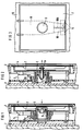
- the manual hazard detector according to the invention has a newly designed actuating mechanism 19 which is formed by the operating lever 9, the operating element 3 and the resilient element, here a leaf spring 10.
- a trough 7 is placed on the printed circuit board 8 with one or more pressure switches 5 - two are shown here.
- the control lever 9, the control element 3 (button) and, as a resilient element, the leaf spring 10 are located between the trough 7 and the printed circuit board 8.
- the control lever 9 is fixed on the upper side and rotatably mounted (FIG. 9a).
- the leaf spring 10 made of spring plate is attached to the operating lever 9, for example with a snap connection.
- the leaf spring 10 is longitudinally slotted in this exemplary embodiment (FIG. 10b).
- a compression spring 6 holds the actuation button or the control element 3, the control lever 9 and the leaf spring 10 in the rest position, ie the indirectly actuated detector is ready for operation in the rest position.
- detector type A control element 3 rests on the glass pane, ie on fragile element 4 (FIG.).
- the trough 7 forms the counterpart for the control element 3.
- actuating mechanism 19 is in one piece, e.g. as a molded plastic part, i.e. the operating lever 9, the operating element 3 and the resilient element 12 are made from one piece and form the actuating mechanism 19.
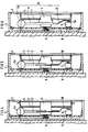
- FIGS. 7a, 7b and 7c A further embodiment of the invention is shown in FIGS. 7a, 7b and 7c. 4 and 5, a spring plate 11 is provided instead of the leaf spring 10, which is rotatably attached to the operating lever 9 by means of a rotary bearing 9c.
- the spring plate 11 can only bend to one side.
- Fig. 7a shows the basic structure
- Fig.7b and 7c the function
- Fig. 7b shows the directly operated detector type A
- Fig.7c shows the indirectly operated detector type B.
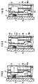
- 8 and 9 show two different embodiments for a directly operated detector (type A).
- 8 shows a so-called spring button detector, after which the glass spring 4 (fragile element), the compression spring 6 presses the spring button 3 (operating element) in the direction of the arrow.
- the leaf spring 10 is supported on the tub 7, whereby the free end 10a of the leaf spring 10 is moved in the opposite direction and actuates the pressure switch 5 on the printed circuit board 8, which leads to an alarm being triggered.
- the operating lever 9 can also be pressed in as far as possible by high impact energy. In this case, too, an alarm is triggered because the spring button detector also behaves like a push button detector.
- the operating lever is fixed in the alarm position, but this is not shown.
- Fig. 9 shows a so-called tilting glass version.
- the disc 4 breaks at the predetermined breaking point 4a (scoring on the inside of the disc in the middle of the button) and tilts in the pressure direction as shown.
- the control button 3 and the leaf spring 10 are moved in the direction of the arrow and the alarm is triggered.
- This type of direct activity is common in some European countries, e.g. Finland and England, common.
- a transparent film 4b can be inserted or glued on the pane on the outside of the detector in all versions.
- Fig. 10 there is again an indirectly operated detector, a so-called push-button version (type B).
- a so-called push-button version type B
- the leaf spring 10 presses directly on the switch button 5a of the switch 5 and triggers the alarm.
- the operating lever 4 is then fixed in the alarm position by a bolt, not shown here.
Landscapes
- Business, Economics & Management (AREA)
- Emergency Management (AREA)
- Physics & Mathematics (AREA)
- General Physics & Mathematics (AREA)
- Push-Button Switches (AREA)
- Burglar Alarm Systems (AREA)
- Geophysics And Detection Of Objects (AREA)
- Emergency Alarm Devices (AREA)
- Power-Operated Mechanisms For Wings (AREA)
- Rotary Switch, Piano Key Switch, And Lever Switch (AREA)
Applications Claiming Priority (2)
| Application Number | Priority Date | Filing Date | Title |
|---|---|---|---|
| DE4234515 | 1992-10-13 | ||
| DE4234515 | 1992-10-13 |
Publications (2)
| Publication Number | Publication Date |
|---|---|
| EP0592925A1 true EP0592925A1 (fr) | 1994-04-20 |
| EP0592925B1 EP0592925B1 (fr) | 1998-01-21 |
Family
ID=6470369
Family Applications (1)
| Application Number | Title | Priority Date | Filing Date |
|---|---|---|---|
| EP93116095A Expired - Lifetime EP0592925B1 (fr) | 1992-10-13 | 1993-10-05 | Avertisseur manuel de risques |
Country Status (4)
| Country | Link |
|---|---|
| EP (1) | EP0592925B1 (fr) |
| AT (1) | ATE162651T1 (fr) |
| DE (1) | DE59308032D1 (fr) |
| ES (1) | ES2111684T3 (fr) |
Cited By (9)
| Publication number | Priority date | Publication date | Assignee | Title |
|---|---|---|---|---|
| EP1288881A1 (fr) * | 2001-09-03 | 2003-03-05 | Siemens Building Technologies AG | Avertisseur manuel de risques |
| DE10350762A1 (de) * | 2003-10-30 | 2005-06-09 | Novar Gmbh | Von Hand auslösbarer Gefahrenmelder |
| EP1612756A3 (fr) * | 2004-07-01 | 2006-12-27 | European Safety Systems Ltd | Point d'appel d'alarme |
| AT500322B1 (de) * | 2004-04-15 | 2007-09-15 | Novar Gmbh | Manueller gefahrenmelder |
| CN100430968C (zh) * | 2003-05-28 | 2008-11-05 | 瑞士西门子有限公司 | 手动式危险警报器 |
| EP2091032A3 (fr) * | 2008-02-14 | 2011-05-18 | Synaps Technology S.r.l. | Point d'appel manuel pour systèmes d'alarme en cas d'incendie |
| US20180330896A1 (en) * | 2017-03-07 | 2018-11-15 | Karl A. Burkett | Physical Barrier Breach Sensor |
| RU185715U1 (ru) * | 2018-08-15 | 2018-12-14 | Дмитрий Анатольевич Шильдяев | Извещатель пожарный ручной |
| CN116620353A (zh) * | 2023-05-25 | 2023-08-22 | 阳春新钢铁有限责任公司 | 一种携带式铁路车辆报警仪 |
Families Citing this family (1)
| Publication number | Priority date | Publication date | Assignee | Title |
|---|---|---|---|---|
| DE19845913B4 (de) * | 1998-10-06 | 2007-11-08 | Robert Bosch Gmbh | Einschlagscheiben-Schutzvorrichtung |
Citations (1)
| Publication number | Priority date | Publication date | Assignee | Title |
|---|---|---|---|---|
| US2545854A (en) * | 1950-03-06 | 1951-03-20 | Levy Morris | Fire alarm switch |
-
1993
- 1993-10-05 DE DE59308032T patent/DE59308032D1/de not_active Expired - Fee Related
- 1993-10-05 EP EP93116095A patent/EP0592925B1/fr not_active Expired - Lifetime
- 1993-10-05 AT AT93116095T patent/ATE162651T1/de not_active IP Right Cessation
- 1993-10-05 ES ES93116095T patent/ES2111684T3/es not_active Expired - Lifetime
Patent Citations (1)
| Publication number | Priority date | Publication date | Assignee | Title |
|---|---|---|---|---|
| US2545854A (en) * | 1950-03-06 | 1951-03-20 | Levy Morris | Fire alarm switch |
Cited By (12)
| Publication number | Priority date | Publication date | Assignee | Title |
|---|---|---|---|---|
| EP1288881A1 (fr) * | 2001-09-03 | 2003-03-05 | Siemens Building Technologies AG | Avertisseur manuel de risques |
| US6674032B2 (en) | 2001-09-03 | 2004-01-06 | Siemens Building Technologies Ag | Manual call point |
| CN100430968C (zh) * | 2003-05-28 | 2008-11-05 | 瑞士西门子有限公司 | 手动式危险警报器 |
| DE10350762A1 (de) * | 2003-10-30 | 2005-06-09 | Novar Gmbh | Von Hand auslösbarer Gefahrenmelder |
| DE10350762B4 (de) * | 2003-10-30 | 2007-04-12 | Novar Gmbh | Von Hand auslösbarer Gefahrenmelder |
| AT500322B1 (de) * | 2004-04-15 | 2007-09-15 | Novar Gmbh | Manueller gefahrenmelder |
| EP1612756A3 (fr) * | 2004-07-01 | 2006-12-27 | European Safety Systems Ltd | Point d'appel d'alarme |
| EP2091032A3 (fr) * | 2008-02-14 | 2011-05-18 | Synaps Technology S.r.l. | Point d'appel manuel pour systèmes d'alarme en cas d'incendie |
| US20180330896A1 (en) * | 2017-03-07 | 2018-11-15 | Karl A. Burkett | Physical Barrier Breach Sensor |
| US10566147B2 (en) * | 2017-03-07 | 2020-02-18 | Karl A. Burkett | Physical barrier breach sensor |
| RU185715U1 (ru) * | 2018-08-15 | 2018-12-14 | Дмитрий Анатольевич Шильдяев | Извещатель пожарный ручной |
| CN116620353A (zh) * | 2023-05-25 | 2023-08-22 | 阳春新钢铁有限责任公司 | 一种携带式铁路车辆报警仪 |
Also Published As
| Publication number | Publication date |
|---|---|
| ATE162651T1 (de) | 1998-02-15 |
| EP0592925B1 (fr) | 1998-01-21 |
| DE59308032D1 (de) | 1998-02-26 |
| ES2111684T3 (es) | 1998-03-16 |
Similar Documents
| Publication | Publication Date | Title |
|---|---|---|
| EP0186737B1 (fr) | Dispositif d'introduction d'une carte de données à circuit électronique | |
| EP0592925B1 (fr) | Avertisseur manuel de risques | |
| DE20214209U1 (de) | Doppelkreis-Schalteraufbau mit Überlastungsschutz | |
| DE8119605U1 (de) | "Drucktastenschalter" | |
| EP2633537B1 (fr) | Serrure à carte | |
| EP0024620B1 (fr) | Touche lumineuse pour claviers de machines de bureau et téléscripteurs | |
| EP0035083B1 (fr) | Interrupteur de protection à dispositif de déclenchement manuel | |
| DE19634051C1 (de) | Schalteranordnung mit mindestens einer Drucktaste | |
| DE4312771C2 (de) | Zweistufentaster | |
| DE3129210C2 (de) | Elektrische Schaltvorrichtung | |
| EP0235350A2 (fr) | Interrupteur, en particulier pour véhicule | |
| EP1288881B1 (fr) | Avertisseur manuel de risques | |
| EP1632921A2 (fr) | Avertisseur de danger manuel | |
| EP1965399B1 (fr) | Commutateur d'urgence pour un système d'alerte de danger | |
| DE4005059C2 (de) | Tastschalteranordnung | |
| EP0592926A1 (fr) | Avertisseur manuel de risques | |
| EP1245033B1 (fr) | Commutateur pour ouvre-porte | |
| DE4207128C2 (de) | Kontaktvorrichtung zur elektrischen Überwachung von Eingangstüren | |
| DE1911104C3 (de) | Elektrischer Schnappschalter | |
| DE3034540C2 (de) | Druckknopfschalter | |
| DE2538849C3 (de) | Elektrischer Sicherheitsschalter | |
| EP1482467B1 (fr) | Capteur d'alarme au déclenchement manuel | |
| EP0326807B1 (fr) | Bouton poussoir | |
| DE3908885C1 (en) | Alarm transmitter | |
| DE1655085B2 (de) | Drucktastenschalter fuer fahrzeuge |
Legal Events
| Date | Code | Title | Description |
|---|---|---|---|
| PUAI | Public reference made under article 153(3) epc to a published international application that has entered the european phase |
Free format text: ORIGINAL CODE: 0009012 |
|
| AK | Designated contracting states |
Kind code of ref document: A1 Designated state(s): AT BE CH DE DK ES FR GB GR IT LI LU NL PT |
|
| 17P | Request for examination filed |
Effective date: 19940519 |
|
| GRAG | Despatch of communication of intention to grant |
Free format text: ORIGINAL CODE: EPIDOS AGRA |
|
| 17Q | First examination report despatched |
Effective date: 19970117 |
|
| GRAH | Despatch of communication of intention to grant a patent |
Free format text: ORIGINAL CODE: EPIDOS IGRA |
|
| GRAH | Despatch of communication of intention to grant a patent |
Free format text: ORIGINAL CODE: EPIDOS IGRA |
|
| GRAA | (expected) grant |
Free format text: ORIGINAL CODE: 0009210 |
|
| AK | Designated contracting states |
Kind code of ref document: B1 Designated state(s): AT BE CH DE DK ES FR GB GR IT LI LU NL PT |
|
| PG25 | Lapsed in a contracting state [announced via postgrant information from national office to epo] |
Ref country code: GR Free format text: LAPSE BECAUSE OF FAILURE TO SUBMIT A TRANSLATION OF THE DESCRIPTION OR TO PAY THE FEE WITHIN THE PRESCRIBED TIME-LIMIT Effective date: 19980121 |
|
| REF | Corresponds to: |
Ref document number: 162651 Country of ref document: AT Date of ref document: 19980215 Kind code of ref document: T |
|
| REG | Reference to a national code |
Ref country code: CH Ref legal event code: NV Representative=s name: SIEMENS SCHWEIZ AG Ref country code: CH Ref legal event code: EP |
|
| REF | Corresponds to: |
Ref document number: 59308032 Country of ref document: DE Date of ref document: 19980226 |
|
| REG | Reference to a national code |
Ref country code: ES Ref legal event code: FG2A Ref document number: 2111684 Country of ref document: ES Kind code of ref document: T3 |
|
| ET | Fr: translation filed | ||
| ITF | It: translation for a ep patent filed | ||
| GBT | Gb: translation of ep patent filed (gb section 77(6)(a)/1977) |
Effective date: 19980325 |
|
| PG25 | Lapsed in a contracting state [announced via postgrant information from national office to epo] |
Ref country code: PT Free format text: LAPSE BECAUSE OF FAILURE TO SUBMIT A TRANSLATION OF THE DESCRIPTION OR TO PAY THE FEE WITHIN THE PRESCRIBED TIME-LIMIT Effective date: 19980421 Ref country code: DK Free format text: LAPSE BECAUSE OF FAILURE TO SUBMIT A TRANSLATION OF THE DESCRIPTION OR TO PAY THE FEE WITHIN THE PRESCRIBED TIME-LIMIT Effective date: 19980421 |
|
| PG25 | Lapsed in a contracting state [announced via postgrant information from national office to epo] |
Ref country code: LU Free format text: LAPSE BECAUSE OF NON-PAYMENT OF DUE FEES Effective date: 19981005 |
|
| PLBE | No opposition filed within time limit |
Free format text: ORIGINAL CODE: 0009261 |
|
| STAA | Information on the status of an ep patent application or granted ep patent |
Free format text: STATUS: NO OPPOSITION FILED WITHIN TIME LIMIT |
|
| 26N | No opposition filed | ||
| REG | Reference to a national code |
Ref country code: GB Ref legal event code: IF02 |
|
| PGFP | Annual fee paid to national office [announced via postgrant information from national office to epo] |
Ref country code: AT Payment date: 20021004 Year of fee payment: 10 |
|
| PGFP | Annual fee paid to national office [announced via postgrant information from national office to epo] |
Ref country code: GB Payment date: 20021010 Year of fee payment: 10 |
|
| PGFP | Annual fee paid to national office [announced via postgrant information from national office to epo] |
Ref country code: ES Payment date: 20021018 Year of fee payment: 10 |
|
| PGFP | Annual fee paid to national office [announced via postgrant information from national office to epo] |
Ref country code: NL Payment date: 20021021 Year of fee payment: 10 Ref country code: BE Payment date: 20021021 Year of fee payment: 10 |
|
| PGFP | Annual fee paid to national office [announced via postgrant information from national office to epo] |
Ref country code: FR Payment date: 20021023 Year of fee payment: 10 |
|
| PGFP | Annual fee paid to national office [announced via postgrant information from national office to epo] |
Ref country code: DE Payment date: 20021216 Year of fee payment: 10 |
|
| PGFP | Annual fee paid to national office [announced via postgrant information from national office to epo] |
Ref country code: CH Payment date: 20030115 Year of fee payment: 10 |
|
| PG25 | Lapsed in a contracting state [announced via postgrant information from national office to epo] |
Ref country code: GB Free format text: LAPSE BECAUSE OF NON-PAYMENT OF DUE FEES Effective date: 20031005 Ref country code: AT Free format text: LAPSE BECAUSE OF NON-PAYMENT OF DUE FEES Effective date: 20031005 |
|
| PG25 | Lapsed in a contracting state [announced via postgrant information from national office to epo] |
Ref country code: ES Free format text: LAPSE BECAUSE OF NON-PAYMENT OF DUE FEES Effective date: 20031006 |
|
| PG25 | Lapsed in a contracting state [announced via postgrant information from national office to epo] |
Ref country code: LI Free format text: LAPSE BECAUSE OF NON-PAYMENT OF DUE FEES Effective date: 20031031 Ref country code: CH Free format text: LAPSE BECAUSE OF NON-PAYMENT OF DUE FEES Effective date: 20031031 Ref country code: BE Free format text: LAPSE BECAUSE OF NON-PAYMENT OF DUE FEES Effective date: 20031031 |
|
| BERE | Be: lapsed |
Owner name: *SIEMENS A.G. Effective date: 20031031 |
|
| PG25 | Lapsed in a contracting state [announced via postgrant information from national office to epo] |
Ref country code: NL Free format text: LAPSE BECAUSE OF NON-PAYMENT OF DUE FEES Effective date: 20040501 Ref country code: DE Free format text: LAPSE BECAUSE OF NON-PAYMENT OF DUE FEES Effective date: 20040501 |
|
| GBPC | Gb: european patent ceased through non-payment of renewal fee |
Effective date: 20031005 |
|
| REG | Reference to a national code |
Ref country code: CH Ref legal event code: PL |
|
| PG25 | Lapsed in a contracting state [announced via postgrant information from national office to epo] |
Ref country code: FR Free format text: LAPSE BECAUSE OF NON-PAYMENT OF DUE FEES Effective date: 20040630 |
|
| NLV4 | Nl: lapsed or anulled due to non-payment of the annual fee |
Effective date: 20040501 |
|
| REG | Reference to a national code |
Ref country code: FR Ref legal event code: ST |
|
| REG | Reference to a national code |
Ref country code: ES Ref legal event code: FD2A Effective date: 20031006 |
|
| PG25 | Lapsed in a contracting state [announced via postgrant information from national office to epo] |
Ref country code: IT Free format text: LAPSE BECAUSE OF NON-PAYMENT OF DUE FEES;WARNING: LAPSES OF ITALIAN PATENTS WITH EFFECTIVE DATE BEFORE 2007 MAY HAVE OCCURRED AT ANY TIME BEFORE 2007. THE CORRECT EFFECTIVE DATE MAY BE DIFFERENT FROM THE ONE RECORDED. Effective date: 20051005 |