EP0592945A1 - Dispositif hydraulique pour une machine de moulage par injection - Google Patents
Dispositif hydraulique pour une machine de moulage par injection Download PDFInfo
- Publication number
- EP0592945A1 EP0592945A1 EP93116218A EP93116218A EP0592945A1 EP 0592945 A1 EP0592945 A1 EP 0592945A1 EP 93116218 A EP93116218 A EP 93116218A EP 93116218 A EP93116218 A EP 93116218A EP 0592945 A1 EP0592945 A1 EP 0592945A1
- Authority
- EP
- European Patent Office
- Prior art keywords
- control
- valve
- line
- pump
- control valve
- Prior art date
- Legal status (The legal status is an assumption and is not a legal conclusion. Google has not performed a legal analysis and makes no representation as to the accuracy of the status listed.)
- Granted
Links
Images

Classifications
-
- B—PERFORMING OPERATIONS; TRANSPORTING
- B29—WORKING OF PLASTICS; WORKING OF SUBSTANCES IN A PLASTIC STATE IN GENERAL
- B29C—SHAPING OR JOINING OF PLASTICS; SHAPING OF MATERIAL IN A PLASTIC STATE, NOT OTHERWISE PROVIDED FOR; AFTER-TREATMENT OF THE SHAPED PRODUCTS, e.g. REPAIRING
- B29C45/00—Injection moulding, i.e. forcing the required volume of moulding material through a nozzle into a closed mould; Apparatus therefor
- B29C45/17—Component parts, details or accessories; Auxiliary operations
- B29C45/76—Measuring, controlling or regulating
- B29C45/82—Hydraulic or pneumatic circuits
-
- G—PHYSICS
- G05—CONTROLLING; REGULATING
- G05D—SYSTEMS FOR CONTROLLING OR REGULATING NON-ELECTRIC VARIABLES
- G05D16/00—Control of fluid pressure
- G05D16/20—Control of fluid pressure characterised by the use of electric means
- G05D16/2006—Control of fluid pressure characterised by the use of electric means with direct action of electric energy on controlling means
- G05D16/208—Control of fluid pressure characterised by the use of electric means with direct action of electric energy on controlling means using a combination of controlling means as defined in G05D16/2013 and G05D16/2066
-
- B—PERFORMING OPERATIONS; TRANSPORTING
- B29—WORKING OF PLASTICS; WORKING OF SUBSTANCES IN A PLASTIC STATE IN GENERAL
- B29C—SHAPING OR JOINING OF PLASTICS; SHAPING OF MATERIAL IN A PLASTIC STATE, NOT OTHERWISE PROVIDED FOR; AFTER-TREATMENT OF THE SHAPED PRODUCTS, e.g. REPAIRING
- B29C45/00—Injection moulding, i.e. forcing the required volume of moulding material through a nozzle into a closed mould; Apparatus therefor
- B29C45/17—Component parts, details or accessories; Auxiliary operations
- B29C45/76—Measuring, controlling or regulating
- B29C45/82—Hydraulic or pneumatic circuits
- B29C2045/826—Plurality of hydraulic actuators driven by one hydraulic pump
-
- F—MECHANICAL ENGINEERING; LIGHTING; HEATING; WEAPONS; BLASTING
- F15—FLUID-PRESSURE ACTUATORS; HYDRAULICS OR PNEUMATICS IN GENERAL
- F15B—SYSTEMS ACTING BY MEANS OF FLUIDS IN GENERAL; FLUID-PRESSURE ACTUATORS, e.g. SERVOMOTORS; DETAILS OF FLUID-PRESSURE SYSTEMS, NOT OTHERWISE PROVIDED FOR
- F15B2211/00—Circuits for servomotor systems
- F15B2211/20—Fluid pressure source, e.g. accumulator or variable axial piston pump
- F15B2211/205—Systems with pumps
- F15B2211/20507—Type of prime mover
- F15B2211/20515—Electric motor
-
- F—MECHANICAL ENGINEERING; LIGHTING; HEATING; WEAPONS; BLASTING
- F15—FLUID-PRESSURE ACTUATORS; HYDRAULICS OR PNEUMATICS IN GENERAL
- F15B—SYSTEMS ACTING BY MEANS OF FLUIDS IN GENERAL; FLUID-PRESSURE ACTUATORS, e.g. SERVOMOTORS; DETAILS OF FLUID-PRESSURE SYSTEMS, NOT OTHERWISE PROVIDED FOR
- F15B2211/00—Circuits for servomotor systems
- F15B2211/20—Fluid pressure source, e.g. accumulator or variable axial piston pump
- F15B2211/205—Systems with pumps
- F15B2211/2053—Type of pump
- F15B2211/20546—Type of pump variable capacity
-
- F—MECHANICAL ENGINEERING; LIGHTING; HEATING; WEAPONS; BLASTING
- F15—FLUID-PRESSURE ACTUATORS; HYDRAULICS OR PNEUMATICS IN GENERAL
- F15B—SYSTEMS ACTING BY MEANS OF FLUIDS IN GENERAL; FLUID-PRESSURE ACTUATORS, e.g. SERVOMOTORS; DETAILS OF FLUID-PRESSURE SYSTEMS, NOT OTHERWISE PROVIDED FOR
- F15B2211/00—Circuits for servomotor systems
- F15B2211/20—Fluid pressure source, e.g. accumulator or variable axial piston pump
- F15B2211/265—Control of multiple pressure sources
-
- F—MECHANICAL ENGINEERING; LIGHTING; HEATING; WEAPONS; BLASTING
- F15—FLUID-PRESSURE ACTUATORS; HYDRAULICS OR PNEUMATICS IN GENERAL
- F15B—SYSTEMS ACTING BY MEANS OF FLUIDS IN GENERAL; FLUID-PRESSURE ACTUATORS, e.g. SERVOMOTORS; DETAILS OF FLUID-PRESSURE SYSTEMS, NOT OTHERWISE PROVIDED FOR
- F15B2211/00—Circuits for servomotor systems
- F15B2211/30—Directional control
- F15B2211/31—Directional control characterised by the positions of the valve element
- F15B2211/3144—Directional control characterised by the positions of the valve element the positions being continuously variable, e.g. as realised by proportional valves
-
- F—MECHANICAL ENGINEERING; LIGHTING; HEATING; WEAPONS; BLASTING
- F15—FLUID-PRESSURE ACTUATORS; HYDRAULICS OR PNEUMATICS IN GENERAL
- F15B—SYSTEMS ACTING BY MEANS OF FLUIDS IN GENERAL; FLUID-PRESSURE ACTUATORS, e.g. SERVOMOTORS; DETAILS OF FLUID-PRESSURE SYSTEMS, NOT OTHERWISE PROVIDED FOR
- F15B2211/00—Circuits for servomotor systems
- F15B2211/30—Directional control
- F15B2211/32—Directional control characterised by the type of actuation
- F15B2211/327—Directional control characterised by the type of actuation electrically or electronically
-
- F—MECHANICAL ENGINEERING; LIGHTING; HEATING; WEAPONS; BLASTING
- F15—FLUID-PRESSURE ACTUATORS; HYDRAULICS OR PNEUMATICS IN GENERAL
- F15B—SYSTEMS ACTING BY MEANS OF FLUIDS IN GENERAL; FLUID-PRESSURE ACTUATORS, e.g. SERVOMOTORS; DETAILS OF FLUID-PRESSURE SYSTEMS, NOT OTHERWISE PROVIDED FOR
- F15B2211/00—Circuits for servomotor systems
- F15B2211/60—Circuit components or control therefor
- F15B2211/63—Electronic controllers
- F15B2211/6303—Electronic controllers using input signals
- F15B2211/634—Electronic controllers using input signals representing a state of a valve
Definitions
- the invention relates to a hydraulic device for hydraulic consumers on an injection molding machine for processing plastics or comparable plastic or plastifiable masses according to the preamble of claim 1.
- the energy consumption of the control pump is adapted to the respective performance requirements of a lower limit, by selecting a just sufficient constant operating pressure gradient that can be preset on the control element of the control pump as the basis for operation and control.
- the known control device satisfies extremely different operating requirements, because a quantity or pressure setting of the control valve which deviates from the setpoint value can alternatively be traced back to the setpoint value by means of a pressure sensor, displacement sensor or section voltage converter in the control circuit. With this device, however, only the upstream side of the consumer can be influenced.
- Another hydraulic device is known from DE-PS 34 47 709, in which several supply lines are alternatively connected to a common control return line via a shuttle valve.
- the branch supply line of lower pressure is provided with a regulating device for regulating the delivery flow setpoint deviation caused by a pressure asymmetry.
- the invention has for its object to develop a hydraulic device of the type mentioned in such a way that cost-effective regulation or control of the consumer in two directions of action takes place precisely and with little energy via a control valve.
- This solution has the advantage that the respective consumers do not need a directional valve, but rather the physical variables speed or speed, position, pressure or force are controlled or regulated in two directions of action via the central unit.
- the consumers are only switched on via the switching valves, so that the control is simple and easy to maintain. Since both the inflow and the backflow side can nevertheless be controlled or regulated, a better and more comfortable regulation can take place despite this cost reduction compared to the prior art.
- the disadvantage is consciously accepted that the resistance of the control valve to the consumer causes greater resistance and an increased natural vibration behavior, which reduce the dynamics of a control, since these disadvantages are compensated for by the advantages obtained.
- the basic requirements for central speed, pressure and position control for the hydraulic circuit of the injection molding machine are created by a higher-level electronic control or regulating device.
- the control valve works in conjunction with the control pump like an inflow flow control.
- the oil displaced by the consumer is throttled in connection with an embodiment according to claim 3 via the respective engaged control edge in the drain.
- This allows cylinders or hydraulic motors to be accelerated and braked in a controlled manner.
- This hydraulic design is necessary for position and force control based on the principle of a hydraulic full bridge.
- control pumps By using several control pumps connected in parallel, it is possible, on the one hand, to increase the volume flow for a control valve if necessary, or to provide several control or regulating circuits next to one another, the pump capacities of the individual control pumps being able to be superimposed as needed, which contributes to energy saving.
- volume flows that are not currently required can be loaded into the storage device and then discharged via one or more control or regulating circuits. This is particularly noticeable in an energetically favorable mode of operation with several control circuits.
- a high speed can also be regulated by means of the memory.
- An embodiment according to claim 9 enables multi-size control, which can be constructed analogously but also digitally for cost reasons.
- An embodiment according to claim 10 enables the oil displaced in the pump line to feed back a high speed in spite of the fact that the mode of operation is energetically favorable.
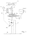
- the hydraulic device is intended for hydraulic consumers V, which in the exemplary embodiment are on an injection molding machine for processing plastics or comparable plastic or plasticizable materials, such as e.g. ceramic masses is used.
- FIG. 1 it has a 4/3-way valve designed as a control valve 15 with three switching positions, which can be controlled at least by means of at least one transducer by comparing actual values with the setpoints given to the control unit R.
- the control pump 18 feeds the consumers V via a supply line 19 guided via the control valve.
- injection cylinders, metering motors, mold clamping units, ejectors, core pulls or other units can be considered.
- the return flow line 21 is also routed via the centrally arranged control valve 15.
- a central arrangement of the control valve 15 is advantageous if the friction losses on the consumer lines 19 are to be kept as low as possible.
- the control valve is connected to the consumers via the connection valves 22 assigned to the consumer (FIG. 2).
- a measuring transducer is also assigned to the return flow line 21. This can be two pressure sensors 16, 17 for detecting the differential pressure, a pressure sensor for detecting the highest pressure in both lines, or a single or more sensors for detecting position or speed. A variable is thus recorded which reflects the conditions on both sides of the consumer, this variable for both sides can also be detected jointly by only one sensor. The transducers thus output actual values as input variables for the control unit R.
- pressure sensors, speed sensors, position detection means or the like are provided as measurement sensors.
- the function of supply line 19 and return flow line 21 is interchanged.
- the supply line 19 and in position PB the return flow line is the actual supply line.
- the pressure medium displaced by the consumer is throttled in the drain via the control edge B-T or A-T of the control valve which is in engagement.
- the middle switching position of the control valve is designed as a blocking position, which allows locking, for example in the holding pressure phase of the injection molding machine.
- the control valve can be directly controlled or pilot-controlled and can be equipped with one or two control magnets 15a, 15b. For safety reasons, the use of two control magnets is desirable.
- the feedback of the actual pressure value to the control element 18a, 18a 'of the control pump 18,18' takes place via a shuttle valve 23,23 '.
- Alternatively, e.g. Directional control valves, control taps on the control valve or an external pressure supply can be provided.
- the feedback as well as the regulation of the variable pump takes place in connection with the higher-level electronic control unit R.
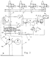
- the feedback provides the control pump 18 with a variable, impressed volume flow Q 1.
- control pump 18 is associated with a further control pump 18 'with a volume flow Q2.
- the one control pump 18 is intended for the control or control circuit I and the second control pump 18 'for the second control or control circuit II.
- Both control circuits are largely identical, so that the reference numerals of the first control circuit are used for the elements of the second control circuit differentiated by a prime.
- the consumer is supplied via the supply line 19 'and the return flow line 21' is guided via the control valve 15 '.
- the pressure sensors 16 ', 17' are also connected via the shuttle valve 23 ' the pump 18 'connected via the control return line 20'.
- the returned oil passes from the control valves 15, 15 'to the tank 38.
- Both control pumps 18, 18' are linked to one another via a connecting line 39 in which a cut-in valve 24 is provided.
- a connecting line 39 in which a cut-in valve 24 is provided.
- the full volume flow Q2 or a partial volume flow to the volume flow Q1 of the control pump 18 can be switched on.
- this connection is also possible in the other direction of action, so that both control circuits can be supplied with the required volume flow as required.
- the return flow from the control valve to the tank 38 takes place via the lines 41, 41 '.
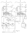
- control or control circuits I and II a memory is added.
- a pressure-regulated pump 18 is shown, which supplies the accumulator via line 40 and the 2/2-way valve 26, provided the control valve 15 'is in its middle position.
- the 2/2-way valve 27 is open and the pressure is detected via the pressure sensor 44.
- the 2/2-way valve 27 can e.g. be designed as a cartridge valve. If the memory is powered, it can be discharged into lines 28 or 40 in each of the two control circuits if necessary. This enables a high speed to be regulated, for example.
- a check valve 45 is provided in the pump train 33 so that there is no backflow when discharging from the reservoir 30 onto the control pump.
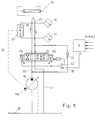
- a 4/4-way valve is used instead of the control valve 15, which has a 4th switching position. In this position, a differential circuit is possible in which the pressure medium displaced by the consumer can be fed into the pump line 33 via a check valve 31, which bridges the 4/4-way valve. This enables around 30% higher speeds with energetically more favorable operation.
- FIG. 2 also shows the electronic control unit R in more detail with regard to its circuit. It works according to the principle of a multivariable control, which is constructed analog or digital.
- a pressure control at least one pressure sensor 16, but better two pressure sensors 16, 17 are provided per control valve, which transmit the actual pressure or force values to the pressure regulator 37, in which the reference variable w 3 is determined for the pressure and force control.
- the line voltage converter 34 the actual position or position values x 1 to x n are determined, which are compared with the desired position value, the position command variable w 1 being determined.
- the speed v is the target speed wherein the speed command is determined to w2 compared.
- the associated actual values are recorded on the consumers by analog or digital sensors for recording the actual values.
- the speed command variable w2 or the position command variable w1 is superordinate and the command variable w3 of the pressure and force control has a limiting effect on the actual manipulated variable y or y1, y2 in the limiter 35.
- the manipulated variables are then transmitted via signal line 43 to comparator 42, which compares the actual position of the control valve with the manipulated variable and, if necessary, causes an actuating movement of the control valve.
- the speed can be controlled or regulated in the control-technical sense.
- the control loop is closed with the electronic control unit. Switchable controller networks are also conceivable for pure pressure or force control.
Landscapes
- Engineering & Computer Science (AREA)
- Physics & Mathematics (AREA)
- Manufacturing & Machinery (AREA)
- Mechanical Engineering (AREA)
- Fluid Mechanics (AREA)
- General Physics & Mathematics (AREA)
- Automation & Control Theory (AREA)
- Fluid-Pressure Circuits (AREA)
- Injection Moulding Of Plastics Or The Like (AREA)
Applications Claiming Priority (2)
| Application Number | Priority Date | Filing Date | Title |
|---|---|---|---|
| DE4234647A DE4234647C1 (de) | 1992-10-14 | 1992-10-14 | Hydraulikeinrichtung an einer Spritzgießmaschine für die Verarbeitung von Kunststoffen oder dergleichen |
| DE4234647 | 1992-10-14 |
Publications (2)
| Publication Number | Publication Date |
|---|---|
| EP0592945A1 true EP0592945A1 (fr) | 1994-04-20 |
| EP0592945B1 EP0592945B1 (fr) | 1997-06-04 |
Family
ID=6470457
Family Applications (1)
| Application Number | Title | Priority Date | Filing Date |
|---|---|---|---|
| EP93116218A Expired - Lifetime EP0592945B1 (fr) | 1992-10-14 | 1993-10-07 | Dispositif hydraulique pour une machine de moulage par injection |
Country Status (5)
| Country | Link |
|---|---|
| EP (1) | EP0592945B1 (fr) |
| JP (1) | JPH0775861B2 (fr) |
| AT (1) | ATE153906T1 (fr) |
| CA (1) | CA2107612A1 (fr) |
| DE (2) | DE4234647C1 (fr) |
Cited By (2)
| Publication number | Priority date | Publication date | Assignee | Title |
|---|---|---|---|---|
| EP1321276A1 (fr) * | 2001-12-21 | 2003-06-25 | Ferromatik Milacron Maschinenbau GmbH | Machine de moulage par injection avec accumulateur hydraulique |
| EP2638293B1 (fr) | 2010-10-18 | 2017-07-05 | Eaton Corporation | Circuit d'entraînement hydraulique à accumulateur architecturé parallèle |
Families Citing this family (8)
| Publication number | Priority date | Publication date | Assignee | Title |
|---|---|---|---|---|
| DE4335403C1 (de) * | 1993-10-18 | 1994-12-15 | Karl Hehl | Hydraulikeinrichtung |
| DE4438604C2 (de) * | 1994-10-28 | 1997-09-11 | Harald Feuerherm | Verfahren zum Steuern einer Blasformanlage |
| US6116142A (en) * | 1996-07-05 | 2000-09-12 | Parker Hannifin Gmbh | Controller for a fluid cylinder |
| DE10208589C2 (de) * | 2001-12-21 | 2003-12-24 | Ferromatik Milacron Maschb Gmb | Spritzgießmaschine |
| DE102016011761A1 (de) * | 2016-10-04 | 2018-04-05 | Günther Zimmer | Greifvorrichtung mit Schaltmodul |
| CN105398573A (zh) * | 2015-12-21 | 2016-03-16 | 保定维特瑞交通设施工程有限责任公司 | 喷气驱动旋翼机构及具有其的直升机 |
| CN112024847A (zh) * | 2020-08-31 | 2020-12-04 | 宁波力劲科技有限公司 | 一种压铸机开锁模的pid控制系统及控制方法 |
| CN119329020A (zh) * | 2023-07-18 | 2025-01-21 | 丹佛斯动力系统(上海)有限公司 | 注塑机开合模液压回路和注塑机系统 |
Citations (3)
| Publication number | Priority date | Publication date | Assignee | Title |
|---|---|---|---|---|
| DE3447709C1 (de) * | 1984-12-28 | 1986-04-30 | Karl 7298 Loßburg Hehl | Steuervorrichtung fuer den hydraulischen Kreislauf einer Kunststoff-Spritzgiessmaschine |
| EP0185984A2 (fr) * | 1984-12-28 | 1986-07-02 | Karl Hehl | Dispositif hydraulique pour le groupe d'injection d'une machine de moulage par injection de matière plastique |
| DE4018334C1 (en) * | 1990-06-08 | 1991-11-07 | Karl 7298 Lossburg De Hehl | Hydraulic appts. for mould closing unit of injection moulder - includes pump control valve on mould closure unit, hydraulic cylinder(s) controlled by 4-4 way valve |
Family Cites Families (1)
| Publication number | Priority date | Publication date | Assignee | Title |
|---|---|---|---|---|
| DE3119095C2 (de) * | 1981-05-14 | 1983-09-01 | Karl 7298 Loßburg Hehl | Steuervorrichtung für den hydraulischen Kreislauf einer Kunststoff-Spritzgießmaschine |
-
1992
- 1992-10-14 DE DE4234647A patent/DE4234647C1/de not_active Expired - Fee Related
-
1993
- 1993-10-04 CA CA002107612A patent/CA2107612A1/fr not_active Abandoned
- 1993-10-07 AT AT93116218T patent/ATE153906T1/de not_active IP Right Cessation
- 1993-10-07 EP EP93116218A patent/EP0592945B1/fr not_active Expired - Lifetime
- 1993-10-07 DE DE59306651T patent/DE59306651D1/de not_active Expired - Fee Related
- 1993-10-14 JP JP5280345A patent/JPH0775861B2/ja not_active Expired - Lifetime
Patent Citations (3)
| Publication number | Priority date | Publication date | Assignee | Title |
|---|---|---|---|---|
| DE3447709C1 (de) * | 1984-12-28 | 1986-04-30 | Karl 7298 Loßburg Hehl | Steuervorrichtung fuer den hydraulischen Kreislauf einer Kunststoff-Spritzgiessmaschine |
| EP0185984A2 (fr) * | 1984-12-28 | 1986-07-02 | Karl Hehl | Dispositif hydraulique pour le groupe d'injection d'une machine de moulage par injection de matière plastique |
| DE4018334C1 (en) * | 1990-06-08 | 1991-11-07 | Karl 7298 Lossburg De Hehl | Hydraulic appts. for mould closing unit of injection moulder - includes pump control valve on mould closure unit, hydraulic cylinder(s) controlled by 4-4 way valve |
Cited By (2)
| Publication number | Priority date | Publication date | Assignee | Title |
|---|---|---|---|---|
| EP1321276A1 (fr) * | 2001-12-21 | 2003-06-25 | Ferromatik Milacron Maschinenbau GmbH | Machine de moulage par injection avec accumulateur hydraulique |
| EP2638293B1 (fr) | 2010-10-18 | 2017-07-05 | Eaton Corporation | Circuit d'entraînement hydraulique à accumulateur architecturé parallèle |
Also Published As
| Publication number | Publication date |
|---|---|
| CA2107612A1 (fr) | 1994-04-15 |
| DE4234647C1 (de) | 1994-01-27 |
| DE59306651D1 (de) | 1997-07-10 |
| JPH06198697A (ja) | 1994-07-19 |
| ATE153906T1 (de) | 1997-06-15 |
| JPH0775861B2 (ja) | 1995-08-16 |
| EP0592945B1 (fr) | 1997-06-04 |
Similar Documents
| Publication | Publication Date | Title |
|---|---|---|
| DE3644736C2 (de) | Steueranordnung für mindestens zwei von mindestens einer Pumpe gespeiste hydraulische Verbraucher | |
| DE4127342C2 (de) | Hydraulisches System mit einer Pumpe | |
| EP0185984B1 (fr) | Dispositif hydraulique pour le groupe d'injection d'une machine de moulage par injection de matière plastique | |
| EP0275968A2 (fr) | Dispositif de commande pour une transmission hydrostatique pour au moins deux utilisateurs | |
| DE2609434C2 (de) | Einrichtung zur Steuerung eines hydraulischen Motors | |
| DE3447709C1 (de) | Steuervorrichtung fuer den hydraulischen Kreislauf einer Kunststoff-Spritzgiessmaschine | |
| DE3209811A1 (de) | Durchflusssteuereinrichtung fuer ein stroemungsfaehiges medium an einer spritzgiessmaschine, insbesondere spritzpresse | |
| EP0073268A1 (fr) | Commande electro-hydraulique pour un piston d'actionnement | |
| DE4108915C2 (de) | Hydraulische Einrichtung zur Druckmittelversorgung eines bevorrechtigten Primärlastkreises | |
| EP0592945B1 (fr) | Dispositif hydraulique pour une machine de moulage par injection | |
| DE102015201318A1 (de) | Hydraulische Steueranordnung zur Druckmittelversorgung wenigstens zweier hydraulischer Verbraucher | |
| DE4302755A1 (de) | Steuereinrichtung zur Regelung einer von zwei zusammenwirkenden Hydraulik-Verbrauchern abhängigen Arbeitskenngröße | |
| DE4228599A1 (de) | Hydraulikkreis fuer die versorgung mehrerer, seriell betriebener verbraucher einer hydraulisch gesteuerten anlage | |
| EP0164602A2 (fr) | Dispositif pour le réglage de la pression et du débit d'une pompe réglable | |
| DE69417153T2 (de) | Steuerungsvorrichtung eines Stellgliedes einer Baumaschine | |
| EP1287900B1 (fr) | Installation de revêtement comprenant une boucle de régulation | |
| EP0190431B1 (fr) | Système hydraulique | |
| DE3011088A1 (de) | Hydraulische antriebsschaltung | |
| DE3733677C2 (fr) | ||
| AT392606B (de) | Hydraulische steuereinrichtung fuer die einspritzeinheit einer kunststoff-spritzgiess- maschine | |
| DE3436246C2 (de) | Steuereinrichtung für einen hydraulisch betriebenen Verbraucher | |
| DE4230183C2 (de) | Steuervorrichtung für Hydromotoren | |
| DE2305593A1 (de) | Steuersystem zur steuerung der geschwindigkeit und der beschleunigung eines hydraulischen mediums | |
| DE4410156B4 (de) | Steuereinrichtung für eine Verstellpumpe | |
| DE4041033C2 (fr) |
Legal Events
| Date | Code | Title | Description |
|---|---|---|---|
| PUAI | Public reference made under article 153(3) epc to a published international application that has entered the european phase |
Free format text: ORIGINAL CODE: 0009012 |
|
| AK | Designated contracting states |
Kind code of ref document: A1 Designated state(s): AT CH DE ES FR GB IT LI NL |
|
| 17P | Request for examination filed |
Effective date: 19941012 |
|
| GRAG | Despatch of communication of intention to grant |
Free format text: ORIGINAL CODE: EPIDOS AGRA |
|
| 17Q | First examination report despatched |
Effective date: 19960813 |
|
| GRAH | Despatch of communication of intention to grant a patent |
Free format text: ORIGINAL CODE: EPIDOS IGRA |
|
| GRAH | Despatch of communication of intention to grant a patent |
Free format text: ORIGINAL CODE: EPIDOS IGRA |
|
| GRAA | (expected) grant |
Free format text: ORIGINAL CODE: 0009210 |
|
| AK | Designated contracting states |
Kind code of ref document: B1 Designated state(s): AT CH DE ES FR GB IT LI NL |
|
| PG25 | Lapsed in a contracting state [announced via postgrant information from national office to epo] |
Ref country code: NL Free format text: LAPSE BECAUSE OF FAILURE TO SUBMIT A TRANSLATION OF THE DESCRIPTION OR TO PAY THE FEE WITHIN THE PRESCRIBED TIME-LIMIT Effective date: 19970604 Ref country code: ES Free format text: THE PATENT HAS BEEN ANNULLED BY A DECISION OF A NATIONAL AUTHORITY Effective date: 19970604 |
|
| REF | Corresponds to: |
Ref document number: 153906 Country of ref document: AT Date of ref document: 19970615 Kind code of ref document: T |
|
| REG | Reference to a national code |
Ref country code: CH Ref legal event code: NV Representative=s name: LUCHS & PARTNER PATENTANWAELTE Ref country code: CH Ref legal event code: EP |
|
| GBT | Gb: translation of ep patent filed (gb section 77(6)(a)/1977) |
Effective date: 19970606 |
|
| REF | Corresponds to: |
Ref document number: 59306651 Country of ref document: DE Date of ref document: 19970710 |
|
| ET | Fr: translation filed | ||
| NLV1 | Nl: lapsed or annulled due to failure to fulfill the requirements of art. 29p and 29m of the patents act | ||
| PLBE | No opposition filed within time limit |
Free format text: ORIGINAL CODE: 0009261 |
|
| STAA | Information on the status of an ep patent application or granted ep patent |
Free format text: STATUS: NO OPPOSITION FILED WITHIN TIME LIMIT |
|
| 26N | No opposition filed | ||
| PGFP | Annual fee paid to national office [announced via postgrant information from national office to epo] |
Ref country code: GB Payment date: 19990915 Year of fee payment: 7 |
|
| PGFP | Annual fee paid to national office [announced via postgrant information from national office to epo] |
Ref country code: FR Payment date: 19991018 Year of fee payment: 7 |
|
| PGFP | Annual fee paid to national office [announced via postgrant information from national office to epo] |
Ref country code: CH Payment date: 19991021 Year of fee payment: 7 |
|
| PGFP | Annual fee paid to national office [announced via postgrant information from national office to epo] |
Ref country code: DE Payment date: 20000824 Year of fee payment: 8 |
|
| PG25 | Lapsed in a contracting state [announced via postgrant information from national office to epo] |
Ref country code: GB Free format text: LAPSE BECAUSE OF NON-PAYMENT OF DUE FEES Effective date: 20001007 |
|
| PGFP | Annual fee paid to national office [announced via postgrant information from national office to epo] |
Ref country code: AT Payment date: 20001023 Year of fee payment: 8 |
|
| PG25 | Lapsed in a contracting state [announced via postgrant information from national office to epo] |
Ref country code: LI Free format text: LAPSE BECAUSE OF NON-PAYMENT OF DUE FEES Effective date: 20001031 Ref country code: CH Free format text: LAPSE BECAUSE OF NON-PAYMENT OF DUE FEES Effective date: 20001031 |
|
| GBPC | Gb: european patent ceased through non-payment of renewal fee |
Effective date: 20001007 |
|
| REG | Reference to a national code |
Ref country code: CH Ref legal event code: PL |
|
| PG25 | Lapsed in a contracting state [announced via postgrant information from national office to epo] |
Ref country code: FR Free format text: LAPSE BECAUSE OF NON-PAYMENT OF DUE FEES Effective date: 20010629 |
|
| REG | Reference to a national code |
Ref country code: FR Ref legal event code: ST |
|
| PG25 | Lapsed in a contracting state [announced via postgrant information from national office to epo] |
Ref country code: AT Free format text: LAPSE BECAUSE OF NON-PAYMENT OF DUE FEES Effective date: 20011007 |
|
| PG25 | Lapsed in a contracting state [announced via postgrant information from national office to epo] |
Ref country code: DE Free format text: LAPSE BECAUSE OF NON-PAYMENT OF DUE FEES Effective date: 20020702 |
|
| PG25 | Lapsed in a contracting state [announced via postgrant information from national office to epo] |
Ref country code: IT Free format text: LAPSE BECAUSE OF NON-PAYMENT OF DUE FEES;WARNING: LAPSES OF ITALIAN PATENTS WITH EFFECTIVE DATE BEFORE 2007 MAY HAVE OCCURRED AT ANY TIME BEFORE 2007. THE CORRECT EFFECTIVE DATE MAY BE DIFFERENT FROM THE ONE RECORDED. Effective date: 20051007 |