EP0592975A2 - Méthode d'accord par synthèse de tension pour récepteurs de signaux de télévision ayant un dispositif de rappel direct de canal - Google Patents
Méthode d'accord par synthèse de tension pour récepteurs de signaux de télévision ayant un dispositif de rappel direct de canal Download PDFInfo
- Publication number
- EP0592975A2 EP0592975A2 EP93116403A EP93116403A EP0592975A2 EP 0592975 A2 EP0592975 A2 EP 0592975A2 EP 93116403 A EP93116403 A EP 93116403A EP 93116403 A EP93116403 A EP 93116403A EP 0592975 A2 EP0592975 A2 EP 0592975A2
- Authority
- EP
- European Patent Office
- Prior art keywords
- tuning
- station
- detected
- television signal
- voltage synthesis
- Prior art date
- Legal status (The legal status is an assumption and is not a legal conclusion. Google has not performed a legal analysis and makes no representation as to the accuracy of the status listed.)
- Withdrawn
Links
Images

Classifications
-
- H—ELECTRICITY
- H03—ELECTRONIC CIRCUITRY
- H03J—TUNING RESONANT CIRCUITS; SELECTING RESONANT CIRCUITS
- H03J1/00—Details of adjusting, driving, indicating, or mechanical control arrangements for resonant circuits in general
- H03J1/0008—Details of adjusting, driving, indicating, or mechanical control arrangements for resonant circuits in general using a central processing unit, e.g. a microprocessor
- H03J1/0033—Details of adjusting, driving, indicating, or mechanical control arrangements for resonant circuits in general using a central processing unit, e.g. a microprocessor for voltage synthesis with a D/A converter
-
- H—ELECTRICITY
- H04—ELECTRIC COMMUNICATION TECHNIQUE
- H04N—PICTORIAL COMMUNICATION, e.g. TELEVISION
- H04N5/00—Details of television systems
- H04N5/44—Receiver circuitry for the reception of television signals according to analogue transmission standards
- H04N5/50—Tuning indicators; Automatic tuning control
-
- H—ELECTRICITY
- H03—ELECTRONIC CIRCUITRY
- H03J—TUNING RESONANT CIRCUITS; SELECTING RESONANT CIRCUITS
- H03J7/00—Automatic frequency control; Automatic scanning over a band of frequencies
- H03J7/02—Automatic frequency control
Definitions
- the present invention relates to a tuning method for voltage synthesis television signal receivers.
- the digital code relative to the desired channel is read from the memory, is converted to an analog value, and the corresponding voltage to such value is applied to the tuner, that is of the normal type having a voltage controlled oscillator (V.C.O).
- V.C.O voltage controlled oscillator
- Such systems also generally provide a so-called automatic tuning circuit(A.F.C.), for replacing the tuning to an acceptable value.
- A.F.C. automatic tuning circuit
- the aim of the present invention is to indicate a tuning method for voltage synthesis television signal receivers, that allows the user, upon the initial turning on of the apparatus, to directly call any channel desired.
- the present invention has as its subject a tuning method for voltage synthesis television signal receivers, characteristic in that a plurality of digital codes, each identifying respectively a voltage corresponding to a television channel, are memorised before the sale of the receiver in a tuning memory of the non volatile digital type, to a corresponding plurality of addresses and that for executing the direct call of the desired channel the user types on a command unit (16) the channel number, that said command unit (16) sends to a control unit (14) of the receiver a corresponding signal and that the control unit reads in the memory the corresponding digital code and sends it to the tuning unit that provides for tuning the desired channel.
- the automatic tuning circuits have the necessity of being sized based on a compromise; it is in fact known that the slope, i.e. the precision, of the AFC circuit is inversely proportional to the pull-in range; as a consequence, so as to guarantee an acceptable precision such circuits can not have a very large grasping field; unfortunately the drifting is generally greater than such field.
- the English patent N. 1 518 712 proposes to memorise a modified digital code, in place of the original, whenever a discrepancy of tuning is detected greater than a prefixed acceptability limit.
- the cited English patent N. 1 520 849 provides that, upon the operation of tuning, it is detected whether the it is to be found outside the aforementioned pull-in range, and, in such case, a cyclic variation of the digital code is executed, so as to vary the frequency and to bring it within the range, and that the code correction be memorised.
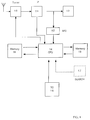
- the tuner is indicated, of the conventional voltage synthesis type; with reference number 11 the combination (substantially conventional) of the intermediate frequency amplifying circuits and signal demodulators is indicated; with reference number 12 the automatic tuning circuit (AFC) is indicated; with reference number 13 the combination of the remaining circuits of the receiver of television signals is indicated, being of the conventional type.
- AFC automatic tuning circuit
- reference number 14 the central control unit (microprocessor or microcontroller) is indicated; reference number 15 indicates the non volatile type memory, but electrically erasable and re-writable, within which the digital codes are memorised corresponding to the tuning voltages of all the channels that can be received by the receiver of television signals in question.
- command organ for sending command signals to the control unit 14;
- command organ can be for example a conventional remote control unit, with the relative receiver.
- an auxiliary command unit is indicated, that can be contained in the receiver, or, for cost reasons, may be available only to the factory and in service stations; such auxiliary command unit serves in sending to the control unit 14 the signals necessary for executing the preliminary search and tuning operation of all the receivable channels, and relative memorising of the relative digital codes in the memory 15.
- reference number 18 indicates a second non volatile memory, utilised for memorising preferred channels; such memory can for example contain twenty or more cells; in each cell, by way of the control unit 14, in following an opportune command executed by the user, through the command unit 16, the correspondence between the number of a channel and the number of the key of the remote control with which the channel can be recalled is memorised.
- system of indirect recall is that normally utilised with voltage synthesis systems, without the possibility of direct call; such system can be mnemonically useful (association of the channel RAI 1 with the key 1, of the channel RAI 2 with the key 2, and so on).
- the voltage synthesis tuning method provides that the microcontroller 14 be coupled to a D/A converter with the necessary resolution, for example 14 bits; for tuning the receiver on a determined channel the local oscillator of the tuner 10 has to oscillate to the central frequency of the channel, having increased the intermediate frequency value.
- the tuning of a station by the system does not finish as mentioned above, but is completed with a sophisticated control.
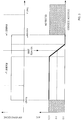
- the microcontroller in the preliminary channel search phase increases the tuning code in such sections as to obtain in output from the voltage controlled oscillator (VCO) of the tuner frequency variations of the order of approximately 500 KHz (speed 1) for each single section (see fig. 2, A); simultaneously the microcontroller tests the identification signal coming from the intermediate frequency integrated circuit 11, with the aim of detecting or not the presence of a station. If the presence of a station is not detected, the microcontroller increases the tuning code a further section (still that producing a frequency variation of approximately 500 KHz) and re-executes the test on the presence of the identification signal coming from the intermediate frequency integrated circuit, with the aim of detecting or not the presence of a station.
- VCO voltage controlled oscillator
- the microcontroller modifies the increment of the tuning code so as to obtain a frequency variation of approximately 200 KHz (speed 2) at each section (see fig. 2, B) . From this moment on, at each section, the contemporary presence of the identification signal and of the signal is tested, coming from the A/D converter, able to discriminate the level of the signal coming from the automatic tuning circuit (AFC) 12.
- AFC automatic tuning circuit
- the microcontroller When the microcontroller detects for the first time the descending section (see fig. 2, C) of the automatic tuning curve (AFC), by way of the reading of the converter A/D, it memorises in the memory 15, the value of the effective tuning code in that moment and modifies the increment of the tuning code so as to obtain the slightest variation possible at each section (approximately 50 KHz, speed 3), in order to have the maximum resolution.
- the microcontroller calculates the avarage value between the actual tuning code and that previously memorised and memorises such avarage in the memory 15, to the address corresponding to the selected channel; in this way the system will carry out a tuning of the channel as close as possible to its ideal.
- the pull-in range results in being very large, and simultaneously the slope of the AFC device results in being very accentuated; in this way both a large pull-in range (assured by the digital search system) and a high tuning precision (assured by the slope of the AFC) are obtained.
- the microcontroller In the channel recall phase the microcontroller has to recall from the memory 15 the previously memorised tuning code, for the D/A converter, the information relative to the band and, eventually, a code relative to the transmission standard, in the case of a multistandard receiver.
- the tuning of the relative station may require variations of the voltage tuning (and therefore of digital codes) being more or less large.
- the microcontroller 14 executes corrections on the previously memorised tuning code, as will now be described; it is however to be noted that, in such phase, the corrected tuning code is not memorised.
- the microcontroller After having charged the tuning data relative to the newly selected station, it tests the presence of the identification signal coming from the integrated circuit of intermediate frequency, with the aims of detecting the presence or not of a station. If the presence of a station is not detected, the microcontroller knows that the drifting has been verified in a negative sense (in fact if the drifting occurs in a positive sense the station results in being present, due to the characteristics of the television signal) and that it is necessary to decrease the agreement frequency respect the actual one (see fig. 3).
- the microcontroller therefore decreases the tuning code by one section (equal to 500 KHz in frequency) and re-executes the test on the identification signal; in the negative case the decrease and successive test are repeated up to a maximum of four times (for a total of approximately 2 MHz), unless the presence of a station is not detected before.
- the microcontroller 14 modifies the variation section of the tuning code in order to obtain a frequency variation of approximately 200 KHz per section. At each section the presence of the identification code and of the signal coming from the A/D converter is tested, indicative of the level of voltage coming from the automatic tuning circuit 12.
- the microcontroller 14 Analysing the information received from the A/D converter the microcontroller 14 is able to establish as to whether the current tuning code brings about a positive or negative mistuning (see fig. 3; in the illustrated case the exact tuning corresponds to 6 volt output from the AFC circuit) .
- the microcontroller 14 modifies the tuning code so as to obtain a frequency variation of approximately 50 KHz in the opposite sense of the mistuning; with successive sections the system is thus brought back to a correct tuning, eliminating the drifting effect.
- the microcontroller 14 also provides for the correction of the drifting of a minor entity, slower in time (for example that due to an eventual antenna converter).
- the microcontroller even during its normal functioning as a receiver, tests the identification signal, coming from the integrated circuit of intermediate frequency 11, for detecting the presence of a station; if the presence of a station is not detected, no correction is carried out; in the presence of a station the microcontroller 14 tests the signal coming from the A/D converter, indicative of the level of voltage coming from the automatic tuning circuit 12; if the microcontroller detects a mistuning, be it negative or positive, it provides for modifying the tuning code as a consequence, in order to obtain a variation of 50 Khz in the opposite sense of the detected mistuning.
Landscapes
- Engineering & Computer Science (AREA)
- Computer Hardware Design (AREA)
- Microelectronics & Electronic Packaging (AREA)
- Multimedia (AREA)
- Signal Processing (AREA)
- Channel Selection Circuits, Automatic Tuning Circuits (AREA)
Applications Claiming Priority (2)
| Application Number | Priority Date | Filing Date | Title |
|---|---|---|---|
| ITTO920828 | 1992-10-14 | ||
| ITTO920828A IT1257123B (it) | 1992-10-14 | 1992-10-14 | Metodo di sintonia a sintesi di tensione per ricevitore di segnali televisivi con chiamata diretta del canale. |
Publications (2)
| Publication Number | Publication Date |
|---|---|
| EP0592975A2 true EP0592975A2 (fr) | 1994-04-20 |
| EP0592975A3 EP0592975A3 (en) | 1994-07-13 |
Family
ID=11410780
Family Applications (1)
| Application Number | Title | Priority Date | Filing Date |
|---|---|---|---|
| EP19930116403 Withdrawn EP0592975A3 (en) | 1992-10-14 | 1993-10-10 | Voltage synthesis tuning method for television signal receivers with direct channel call |
Country Status (2)
| Country | Link |
|---|---|
| EP (1) | EP0592975A3 (fr) |
| IT (1) | IT1257123B (fr) |
Cited By (3)
| Publication number | Priority date | Publication date | Assignee | Title |
|---|---|---|---|---|
| WO1997044897A1 (fr) * | 1996-05-17 | 1997-11-27 | Società Italiana per lo Sviluppo dell'Elettronica S.I.SV.EL. S.p.A. | Procede de programmation de recepteurs de signaux de television et/ou recepteurs de signaux de television mettant en oeuvre ce procede |
| EP0833447A3 (fr) * | 1996-09-30 | 1999-08-18 | Daewoo Electronics Co., Ltd | Circuit d'accord |
| US6744477B2 (en) * | 2000-03-28 | 2004-06-01 | Koninklijke Philips Electronics N.V. | Updating transmitter data stored in a preset channel memory |
Family Cites Families (8)
| Publication number | Priority date | Publication date | Assignee | Title |
|---|---|---|---|---|
| DE2162367C3 (de) * | 1971-12-16 | 1983-01-05 | Blaupunkt-Werke Gmbh, 3200 Hildesheim | Schaltungsanordnung zur automatischen, elektronischen Scharfabstimmung in einem Fernsehempfänger |
| JPS5826693B2 (ja) * | 1975-11-22 | 1983-06-04 | ソニー株式会社 | センキヨクソウチ |
| US4025953A (en) * | 1975-11-26 | 1977-05-24 | Quasar Electronics Corporation | Frequency synthesizer tuning system for television receivers |
| DE2748997C2 (de) * | 1977-11-02 | 1985-08-29 | Telefunken electronic GmbH, 7100 Heilbronn | Schaltungsanordnung für einen automatischen Sendersuchlauf und zur automatischen Scharfabstimmung für einen Überlagerungsempfänger |
| GB2064905B (en) * | 1979-11-30 | 1983-10-05 | Smiths Industries Ltd | Radio receiver tuning |
| US4525866A (en) * | 1983-11-07 | 1985-06-25 | Zenith Electronics Corporation | Stack memory tuning |
| US5152011A (en) * | 1987-07-27 | 1992-09-29 | Schwob Pierre R | Broadcast receiver capable of automatic station identification and format-scanning based on an internal database updatable via data reception over the airwaves |
| US4969209A (en) * | 1987-07-27 | 1990-11-06 | Prs Corporation | Broadcast receiver capable of selecting stations based upon geographical location and program format |
-
1992
- 1992-10-14 IT ITTO920828A patent/IT1257123B/it active IP Right Grant
-
1993
- 1993-10-10 EP EP19930116403 patent/EP0592975A3/en not_active Withdrawn
Cited By (3)
| Publication number | Priority date | Publication date | Assignee | Title |
|---|---|---|---|---|
| WO1997044897A1 (fr) * | 1996-05-17 | 1997-11-27 | Società Italiana per lo Sviluppo dell'Elettronica S.I.SV.EL. S.p.A. | Procede de programmation de recepteurs de signaux de television et/ou recepteurs de signaux de television mettant en oeuvre ce procede |
| EP0833447A3 (fr) * | 1996-09-30 | 1999-08-18 | Daewoo Electronics Co., Ltd | Circuit d'accord |
| US6744477B2 (en) * | 2000-03-28 | 2004-06-01 | Koninklijke Philips Electronics N.V. | Updating transmitter data stored in a preset channel memory |
Also Published As
| Publication number | Publication date |
|---|---|
| IT1257123B (it) | 1996-01-05 |
| EP0592975A3 (en) | 1994-07-13 |
| ITTO920828A0 (it) | 1992-10-14 |
| ITTO920828A1 (it) | 1994-04-14 |
Similar Documents
| Publication | Publication Date | Title |
|---|---|---|
| US4334323A (en) | Self tracking tuner | |
| US4542533A (en) | Tuning system with automatic frequency control | |
| CA1154098A (fr) | Syntonisateur a exploration avec dispositif de selection directe des canaux | |
| KR910001650B1 (ko) | 방송 수신기 | |
| US4217552A (en) | Receiver | |
| KR960012796B1 (ko) | 자동 동조 장치 | |
| CA1049165A (fr) | Dispositif d'accord de frequence automatique | |
| EP0607810B1 (fr) | Procédé d'accord et de mémorisation, compatible avec une pluralité de récepteurs de signaux de télévision | |
| US4819069A (en) | Television signal selection device | |
| CA1057432A (fr) | Selecteur de canaux | |
| KR0176719B1 (ko) | 안정상태 검출 장치를 갖는 동조 시스템 | |
| US4360832A (en) | Frequency synthesizer tuning system for television receivers | |
| US4142157A (en) | Tuning system equalized with the slope factor of the tuning curve | |
| EP0273031B1 (fr) | Commande de syntonisation rapide caracterisee pour un systeme de television | |
| EP0626775A1 (fr) | Dispositif d'accord automatique comportant un circuit de synthèse de tension et une mémoire numérique | |
| JPS601973B2 (ja) | 電子同調チユーナの自動選局装置 | |
| KR100322583B1 (ko) | 고속 채널 탐색 방법과 장치 | |
| KR100215143B1 (ko) | 텔레비젼세트 | |
| KR0129821B1 (ko) | 텔레비젼의 채널 자동 선국장치 | |
| KR920008367Y1 (ko) | 전환 스위치를 사용한 메모리 채널 선국 회로 | |
| KR100314963B1 (ko) | 방송수신기의방송수신방법 | |
| KR960011735B1 (ko) | 비데오 카셋트 레코더의 녹화 예약방법 | |
| KR0164708B1 (ko) | 오토 튜닝 방법 | |
| KR0147985B1 (ko) | 다중 채널 자동 선국 방법 | |
| JPS6174412A (ja) | テレビジヨンチユ−ナ |
Legal Events
| Date | Code | Title | Description |
|---|---|---|---|
| PUAI | Public reference made under article 153(3) epc to a published international application that has entered the european phase |
Free format text: ORIGINAL CODE: 0009012 |
|
| AK | Designated contracting states |
Kind code of ref document: A2 Designated state(s): AT CH DE ES FR GB IE IT LI NL PT |
|
| PUAL | Search report despatched |
Free format text: ORIGINAL CODE: 0009013 |
|
| AK | Designated contracting states |
Kind code of ref document: A3 Designated state(s): AT CH DE ES FR GB IE IT LI NL PT |
|
| 17P | Request for examination filed |
Effective date: 19941231 |
|
| 17Q | First examination report despatched |
Effective date: 19970131 |
|
| STAA | Information on the status of an ep patent application or granted ep patent |
Free format text: STATUS: THE APPLICATION IS DEEMED TO BE WITHDRAWN |
|
| 18D | Application deemed to be withdrawn |
Effective date: 19980501 |