EP0593051B1 - Tintanstrahlaufzeichnungsgerät - Google Patents
Tintanstrahlaufzeichnungsgerät Download PDFInfo
- Publication number
- EP0593051B1 EP0593051B1 EP93116626A EP93116626A EP0593051B1 EP 0593051 B1 EP0593051 B1 EP 0593051B1 EP 93116626 A EP93116626 A EP 93116626A EP 93116626 A EP93116626 A EP 93116626A EP 0593051 B1 EP0593051 B1 EP 0593051B1
- Authority
- EP
- European Patent Office
- Prior art keywords
- ink
- heater
- orifice
- volume
- passage
- Prior art date
- Legal status (The legal status is an assumption and is not a legal conclusion. Google has not performed a legal analysis and makes no representation as to the accuracy of the status listed.)
- Expired - Lifetime
Links
- 230000005499 meniscus Effects 0.000 claims description 24
- 239000007788 liquid Substances 0.000 description 27
- 239000000463 material Substances 0.000 description 16
- 239000011358 absorbing material Substances 0.000 description 13
- 230000008859 change Effects 0.000 description 9
- 230000007423 decrease Effects 0.000 description 9
- 230000033001 locomotion Effects 0.000 description 8
- 239000003570 air Substances 0.000 description 7
- 238000000034 method Methods 0.000 description 6
- 239000012530 fluid Substances 0.000 description 5
- 238000010438 heat treatment Methods 0.000 description 5
- 230000009471 action Effects 0.000 description 4
- 238000009835 boiling Methods 0.000 description 4
- 238000004140 cleaning Methods 0.000 description 4
- 230000000694 effects Effects 0.000 description 4
- 238000011084 recovery Methods 0.000 description 4
- 230000004044 response Effects 0.000 description 4
- 238000007789 sealing Methods 0.000 description 4
- 238000011144 upstream manufacturing Methods 0.000 description 4
- 230000010365 information processing Effects 0.000 description 3
- 238000004519 manufacturing process Methods 0.000 description 3
- 230000007246 mechanism Effects 0.000 description 3
- 238000007639 printing Methods 0.000 description 3
- 230000008569 process Effects 0.000 description 3
- 230000003111 delayed effect Effects 0.000 description 2
- 238000011161 development Methods 0.000 description 2
- 239000002184 metal Substances 0.000 description 2
- 238000005192 partition Methods 0.000 description 2
- 229920002492 poly(sulfone) Polymers 0.000 description 2
- 230000009467 reduction Effects 0.000 description 2
- 239000011347 resin Substances 0.000 description 2
- 229920005989 resin Polymers 0.000 description 2
- 230000000717 retained effect Effects 0.000 description 2
- 239000007787 solid Substances 0.000 description 2
- 230000000087 stabilizing effect Effects 0.000 description 2
- 239000004695 Polyether sulfone Substances 0.000 description 1
- 239000004721 Polyphenylene oxide Substances 0.000 description 1
- 239000004743 Polypropylene Substances 0.000 description 1
- 239000012080 ambient air Substances 0.000 description 1
- 238000013459 approach Methods 0.000 description 1
- 230000005540 biological transmission Effects 0.000 description 1
- 230000015572 biosynthetic process Effects 0.000 description 1
- 229920005549 butyl rubber Polymers 0.000 description 1
- 239000003086 colorant Substances 0.000 description 1
- 238000004891 communication Methods 0.000 description 1
- 230000008602 contraction Effects 0.000 description 1
- 238000013461 design Methods 0.000 description 1
- 238000010586 diagram Methods 0.000 description 1
- 238000009826 distribution Methods 0.000 description 1
- 238000001704 evaporation Methods 0.000 description 1
- 230000008020 evaporation Effects 0.000 description 1
- 230000001747 exhibiting effect Effects 0.000 description 1
- 230000005484 gravity Effects 0.000 description 1
- 230000006872 improvement Effects 0.000 description 1
- 238000002347 injection Methods 0.000 description 1
- 239000007924 injection Substances 0.000 description 1
- 238000011835 investigation Methods 0.000 description 1
- 239000011344 liquid material Substances 0.000 description 1
- 238000005259 measurement Methods 0.000 description 1
- 239000000203 mixture Substances 0.000 description 1
- 239000012778 molding material Substances 0.000 description 1
- 238000000465 moulding Methods 0.000 description 1
- 230000006911 nucleation Effects 0.000 description 1
- 238000010899 nucleation Methods 0.000 description 1
- 230000035515 penetration Effects 0.000 description 1
- 229920006393 polyether sulfone Polymers 0.000 description 1
- 229920006380 polyphenylene oxide Polymers 0.000 description 1
- -1 polypropylene Polymers 0.000 description 1
- 229920001155 polypropylene Polymers 0.000 description 1
- 238000003825 pressing Methods 0.000 description 1
- 230000005855 radiation Effects 0.000 description 1
- 230000001846 repelling effect Effects 0.000 description 1
- 230000000630 rising effect Effects 0.000 description 1
- 229920002379 silicone rubber Polymers 0.000 description 1
- 239000004945 silicone rubber Substances 0.000 description 1
- 238000005549 size reduction Methods 0.000 description 1
- 239000011343 solid material Substances 0.000 description 1
- 230000002269 spontaneous effect Effects 0.000 description 1
- 230000003068 static effect Effects 0.000 description 1
- 239000000758 substrate Substances 0.000 description 1
- XLYOFNOQVPJJNP-UHFFFAOYSA-N water Substances O XLYOFNOQVPJJNP-UHFFFAOYSA-N 0.000 description 1
Images







Classifications
-
- B—PERFORMING OPERATIONS; TRANSPORTING
- B41—PRINTING; LINING MACHINES; TYPEWRITERS; STAMPS
- B41J—TYPEWRITERS; SELECTIVE PRINTING MECHANISMS, i.e. MECHANISMS PRINTING OTHERWISE THAN FROM A FORME; CORRECTION OF TYPOGRAPHICAL ERRORS
- B41J2/00—Typewriters or selective printing mechanisms characterised by the printing or marking process for which they are designed
- B41J2/005—Typewriters or selective printing mechanisms characterised by the printing or marking process for which they are designed characterised by bringing liquid or particles selectively into contact with a printing material
- B41J2/01—Ink jet
- B41J2/135—Nozzles
- B41J2/14—Structure thereof only for on-demand ink jet heads
- B41J2/14016—Structure of bubble jet print heads
- B41J2/14032—Structure of the pressure chamber
- B41J2/1404—Geometrical characteristics
-
- B—PERFORMING OPERATIONS; TRANSPORTING
- B41—PRINTING; LINING MACHINES; TYPEWRITERS; STAMPS
- B41J—TYPEWRITERS; SELECTIVE PRINTING MECHANISMS, i.e. MECHANISMS PRINTING OTHERWISE THAN FROM A FORME; CORRECTION OF TYPOGRAPHICAL ERRORS
- B41J2/00—Typewriters or selective printing mechanisms characterised by the printing or marking process for which they are designed
- B41J2/005—Typewriters or selective printing mechanisms characterised by the printing or marking process for which they are designed characterised by bringing liquid or particles selectively into contact with a printing material
- B41J2/01—Ink jet
- B41J2/135—Nozzles
- B41J2/14—Structure thereof only for on-demand ink jet heads
- B41J2002/14379—Edge shooter
-
- B—PERFORMING OPERATIONS; TRANSPORTING
- B41—PRINTING; LINING MACHINES; TYPEWRITERS; STAMPS
- B41J—TYPEWRITERS; SELECTIVE PRINTING MECHANISMS, i.e. MECHANISMS PRINTING OTHERWISE THAN FROM A FORME; CORRECTION OF TYPOGRAPHICAL ERRORS
- B41J2202/00—Embodiments of or processes related to ink-jet or thermal heads
- B41J2202/01—Embodiments of or processes related to ink-jet heads
- B41J2202/11—Embodiments of or processes related to ink-jet heads characterised by specific geometrical characteristics
Definitions
- an ink supply system to the ink supply port has an ink retaining force resulting from capillary force
- the ink supply system for the recording head is in the form of an ink container retaining the ink using sponge or the like (as in the case of ink jet cartridge) or in the case that the distance between the ink container and the ink passage is very long and narrow
- initial several ink ejections in the case of continuous ejection exhibits instable volumes of the ink droplet, with the result of blurred print.
- the vacuum in the ink passage 1 is x 1 .
- the vacuum increases to x 3 instantaneously due to the fluid inertia (fluid length/cross-sectional area), and the vacuum gradually decreases in a region y.
- the constant vacuum is established in a region z after t 2 . The increase of the vacuum upon the start of ejection results in blurrness of the print.
- Figure 15 is a schematic perspective view of an ink jet head cartridge according to an embodiment of the present invention.
- Vdlim S 0 x OH
- Figure 6 shows a relationship between an orifice area S 0 and an ejection volume Vd. If S 0 x OH > Vd , Vd is not influenced by the orifice area S 0 due to the manufacturing tolerances. This is the condition for preventing the blurred print.
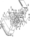
- the legs of the confining spring 500 are engaged with the bottom surface of the supporting member 300 through holes 3121 of the supporting material 300 to sandwich the heater board and the top plate 1300 between itself and the supporting member 300, by which the heater board 100 and the top plate 1300 are secured pressed and fixed to the supporting member 300 by the urging force of the confining spring 500 and the apron 501.
- the supporting material 300 is provided with two positioning holes 312 engageable with two positioning projections 1012 of the ink container and two positioning holes 1900 engageable with two positioning and heat fusing fixing projections 1800. It is also provided at the rear side with positioning projections 2500 and 2600, corresponding to the carriage of the main assembly.
- the supporting member 300 also comprises a hole 320 for permitting penetration of the ink supply pipe 2200, which will be described hereinafter, to permit the ink supply from the ink container.
- the mounting of the wiring board 200 relative to the supporting member 300 is accomplished by bonding with bonding material or the like.
- a small width slit 1700 (smaller than the space) is provided in the upper surface of the cartridge, thus preventing the temperature rise, without influence to the temperature distribution uniformity function of the entire unit IJU being influenced of the ambience.
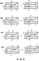
- the MH distance upon the start of the bubble creation for the second dot satisfy: MH x S 0 > V d1
- V OH is a volume of the ink passages in front of the heater edge adjacent the orifice.
- the time t m is determined by the impedances and reactances of the recording head and the ink container, and is normally 5 - 30 ⁇ sec.
- Figure 12 shows the comparison of the change of the ejected volume with time between the prior art example and this embodiment.
- Figure 12, (A) shows the vacuum change shown in Figure 7, and Figure 12, (B), shows the ejected volume change in the conventional ink passage structure, and (C) shows the ejected volume change in this embodiment.
- Figure 12, (C) shows the reductions of the ejected volume at the time of the ejection start can be minimized.
- the blurrness of the print due to the reduction of the ejection volume, occurred in the conventional ink passage structure can be prevented, and therefore, the ejection can be stabilized even at the start of the ejection.
- a lever 5012 is used to start the sucking operation, and is moved in accordance with the movement of a cam 5020 engageable with the carriage.
- the driving force from the driving motor is controlled through known transmitting means such as clutch mechanism or the like.
- the inside volume V of the ink passage downstream of the front edge of the heater surface (the volume of the ink retained by the capillary force under the normal state of the meniscus) is not less than ⁇ 1/3 x f (kHz) + n ⁇ x Vd .
- f is the maximum driving frequency
- the ink is liquefied, and the liquefied ink may be ejected.
- Another ink material may start to be solidified at the time when it reaches the recording material.
- the present invention is also applicable to such an ink material as is liquefied by the application of the thermal energy.
- Such an ink material may be retained as a liquid or solid material in through holes or recesses formed in a porous sheet as disclosed in Japanese Laid-Open Patent Application No. 56847/1979 and Japanese Laid-Open Patent Application No. 71260/1985. The sheet is faced to the electrothermal transducers. The most effective one for the ink materials described above is the film boiling system.
Landscapes
- Physics & Mathematics (AREA)
- Geometry (AREA)
- Particle Formation And Scattering Control In Inkjet Printers (AREA)
- Ink Jet (AREA)
Claims (3)
- Tintenstrahlaufzeichnungsgerät mit folgenden Bauteilen:einer Öffnung zum Ausstoßen von Tinte;einer Heizvorrichtung zum Erzeugen thermischer Energie, um eine Blase zu erzeugen, so daß die Tinte ausgestoßen wird;einem Tintenkanal zum Zuführen von Tinte zu der Öffnung, wobei der Tintenkanal mit der Heizvorrichtung versehen ist;einem Tintenbehälter, der die dem Tintenkanal zuzuführende Tinte enthält, wobei der Tintenbehälter die Tinte unter Verwendung einer Kapillarkraft zurückhält;wobei die folgende Bedingung erfüllt ist:

V'Me ein Volumen ist, mit dem sich ein Meniskus bei dem anfänglichen Tintenausstoß zurückzieht; und Vd ein Volumen der ausgestoßenen Tinte ist. - Tintenstrahlaufzeichnungsgerät mit folgenden Bauteilen:einer Öffnung zum Ausstoßen von Tinte;einer Heizvorrichtung zum Erzeugen thermischer Energie, um eine Blase zu erzeugen, so daß die Tinte ausgestoßen wird;einem Tintenkanal zum Zuführen von Tinte zu der Öffnung, wobei der Tintenkanal mit der Heizvorrichtung versehen ist;einem Tintenbehälter, der die dem Tintenkanal zuzuführende Tinte enthält, wobei der Tintenbehälter die Tinte unter Verwendung einer Kapillarkraft zurückhält;wobei die folgende Bedingung erfüllt ist:

Vd ein Volumen der ausgestoßenen Tinte ist; F ein Strömungswiderstand von einer Mitte der Heizvorrichtung zu der Öffnung ist; R ein Strömungswiderstand von der Mitte der Heizvorrichtung zu dem Tintenbehälter ist; F' ein Strömungswiderstand von einer durch die Heizvorrichtung erzeugten maximalen Blase zu der Öffnung ist; R' ein Strömungswiderstand von einer durch die Heizvorrichtung erzeugten maximalen Blase zu dem Tintenbehälter ist; und P ein Strömungswiderstand des Tintenbehälters ist. - Tintenstrahlkartusche mit folgenden Bauteilen:einer Öffnung zum Ausstoßen von Tinte;einer Heizvorrichtung zum Erzeugen thermischer Energie, um eine Blase zu erzeugen, so daß die Tinte ausgestoßen wird;einem Tintenkanal zum Zuführen von Tinte zu der Öffnung, wobei der Tintenkanal mit der Heizvorrichtung versehen ist;einem Tintenbehälter, der die dem Tintenkanal zuzuführende Tinte enthält, wobei der Tintenbehälter die Tinte unter Verwendung einer Kapillarkraft zurückhält;wobei die folgende Bedingung erfüllt ist:

Vd ein Volumen der ausgestoßenen Tinte ist; F ein Strömungswiderstand von einer Mitte der Reizvorrichtung zu der Öffnung ist; R ein Strömungswiderstand von der Mitte der Heizvorrichtung zu dem Tintenbehälter ist; F' ein Strömungswiderstand von einer durch die Heizvorrichtung erzeugten maximalen Blase zu der Öffnung ist; R' ein Strömungswiderstand von einer durch die Heizvorrichtung erzeugten maximalen Blase zu dem Tintenbehälter ist; und P ein Strömungswiderstand des Tintenbehälters ist.
Applications Claiming Priority (2)
| Application Number | Priority Date | Filing Date | Title |
|---|---|---|---|
| JP27718092 | 1992-10-15 | ||
| JP277180/92 | 1992-10-15 |
Publications (2)
| Publication Number | Publication Date |
|---|---|
| EP0593051A1 EP0593051A1 (de) | 1994-04-20 |
| EP0593051B1 true EP0593051B1 (de) | 1997-01-22 |
Family
ID=17579927
Family Applications (1)
| Application Number | Title | Priority Date | Filing Date |
|---|---|---|---|
| EP93116626A Expired - Lifetime EP0593051B1 (de) | 1992-10-15 | 1993-10-14 | Tintanstrahlaufzeichnungsgerät |
Country Status (8)
| Country | Link |
|---|---|
| US (1) | US5485186A (de) |
| EP (1) | EP0593051B1 (de) |
| KR (1) | KR970004203B1 (de) |
| CN (1) | CN1092108C (de) |
| AU (2) | AU4903893A (de) |
| CA (1) | CA2108304C (de) |
| DE (1) | DE69307645T2 (de) |
| MX (1) | MX9306436A (de) |
Families Citing this family (10)
| Publication number | Priority date | Publication date | Assignee | Title |
|---|---|---|---|---|
| JP3715696B2 (ja) * | 1994-10-20 | 2005-11-09 | キヤノン株式会社 | 液体吐出ヘッド、ヘッドカートリッジおよび液体吐出装置 |
| SG79917A1 (en) * | 1995-04-26 | 2001-04-17 | Canon Kk | Liquid ejecting method with movable member |
| US5821962A (en) * | 1995-06-02 | 1998-10-13 | Canon Kabushiki Kaisha | Liquid ejection apparatus and method |
| JP3408059B2 (ja) | 1995-09-22 | 2003-05-19 | キヤノン株式会社 | 液体吐出ヘッド、液体吐出装置、および液体吐出装置の回復方法 |
| JP3413063B2 (ja) * | 1996-07-09 | 2003-06-03 | キヤノン株式会社 | 液体吐出方法及び液体吐出ヘッド |
| JPH1024584A (ja) | 1996-07-12 | 1998-01-27 | Canon Inc | 液体吐出ヘッドカートリッジおよび液体吐出装置 |
| AU766832B2 (en) * | 1998-07-28 | 2003-10-23 | Canon Kabushiki Kaisha | Liquid discharging head and liquid discharging method |
| US6386832B1 (en) * | 1998-07-28 | 2002-05-14 | Canon Kabushiki Kaisha | Liquid discharge head, liquid discharge method, and liquid discharge apparatus |
| JP2002029047A (ja) * | 2000-07-13 | 2002-01-29 | Fuji Xerox Co Ltd | インクジェット記録ヘッド及びその製造方法、インクジェット記録装置 |
| KR101602996B1 (ko) * | 2009-10-27 | 2016-03-11 | 휴렛-팩커드 디벨롭먼트 컴퍼니, 엘.피. | 오목한 기판 공동 내에 가열 요소를 갖는 열 잉크젯 프린트헤드 |
Family Cites Families (22)
| Publication number | Priority date | Publication date | Assignee | Title |
|---|---|---|---|---|
| CA1127227A (en) * | 1977-10-03 | 1982-07-06 | Ichiro Endo | Liquid jet recording process and apparatus therefor |
| JPS5936879B2 (ja) * | 1977-10-14 | 1984-09-06 | キヤノン株式会社 | 熱転写記録用媒体 |
| US4330787A (en) * | 1978-10-31 | 1982-05-18 | Canon Kabushiki Kaisha | Liquid jet recording device |
| US4345262A (en) * | 1979-02-19 | 1982-08-17 | Canon Kabushiki Kaisha | Ink jet recording method |
| US4334234A (en) * | 1979-04-02 | 1982-06-08 | Canon Kabushiki Kaisha | Liquid droplet forming apparatus |
| US4463359A (en) * | 1979-04-02 | 1984-07-31 | Canon Kabushiki Kaisha | Droplet generating method and apparatus thereof |
| US4313124A (en) * | 1979-05-18 | 1982-01-26 | Canon Kabushiki Kaisha | Liquid jet recording process and liquid jet recording head |
| AT370213B (de) * | 1980-06-11 | 1983-03-10 | Friedmann & Maier Ag | Regelung einer einspritzeinrichtung fuer mehrzylindrige einspritzbrennkraftmaschinen |
| US4338611A (en) * | 1980-09-12 | 1982-07-06 | Canon Kabushiki Kaisha | Liquid jet recording head |
| GB2087675B (en) * | 1980-10-07 | 1984-03-28 | Texas Instruments Ltd | Electrical inverter |
| GB2104452B (en) * | 1981-06-29 | 1985-07-31 | Canon Kk | Liquid jet recording head |
| US4558333A (en) * | 1981-07-09 | 1985-12-10 | Canon Kabushiki Kaisha | Liquid jet recording head |
| JPS59123670A (ja) * | 1982-12-28 | 1984-07-17 | Canon Inc | インクジエツトヘツド |
| JPS59138461A (ja) * | 1983-01-28 | 1984-08-08 | Canon Inc | 液体噴射記録装置 |
| JPS6071260A (ja) * | 1983-09-28 | 1985-04-23 | Erumu:Kk | 記録装置 |
| US4723136A (en) * | 1984-11-05 | 1988-02-02 | Canon Kabushiki Kaisha | Print-on-demand type liquid jet printing head having main and subsidiary liquid paths |
| JPS62152860A (ja) * | 1985-12-27 | 1987-07-07 | Canon Inc | 液体噴射記録ヘツド |
| CA2025559C (en) * | 1989-09-18 | 1998-09-15 | Masaaki Izumida | Liquid jet recording head and liquid jet recording apparatus having same |
| EP0439633A1 (de) * | 1990-01-02 | 1991-08-07 | Siemens Aktiengesellschaft | Schreibkopf fÀ¼r eine nach dem Thermalwandlerprinzip arbeitende Flüssigkeitsstrahlaufzeichnungsvorrichtung |
| ES2089134T3 (es) * | 1990-06-15 | 1996-10-01 | Canon Kk | Aparato para la impresion por chorros de tinta que utiliza un elemento de generacion de calor. |
| JP2984415B2 (ja) * | 1990-06-15 | 1999-11-29 | キヤノン株式会社 | 発熱素子を用いたインクジェット記録装置 |
| EP0504879B1 (de) * | 1991-03-20 | 1996-10-16 | Canon Kabushiki Kaisha | Flüssigkeitsstrahlaufzeichnungskopf und Flüssigkeitsstrahlaufzeichnungsgerät, welches diesen aufweist |
-
1993
- 1993-10-13 CA CA002108304A patent/CA2108304C/en not_active Expired - Fee Related
- 1993-10-14 DE DE69307645T patent/DE69307645T2/de not_active Expired - Fee Related
- 1993-10-14 KR KR1019930021563A patent/KR970004203B1/ko not_active Expired - Fee Related
- 1993-10-14 US US08/136,106 patent/US5485186A/en not_active Expired - Fee Related
- 1993-10-14 EP EP93116626A patent/EP0593051B1/de not_active Expired - Lifetime
- 1993-10-15 AU AU49038/93A patent/AU4903893A/en not_active Abandoned
- 1993-10-15 MX MX9306436A patent/MX9306436A/es not_active IP Right Cessation
- 1993-10-15 CN CN93115009A patent/CN1092108C/zh not_active Expired - Fee Related
-
1996
- 1996-06-03 AU AU55803/96A patent/AU5580396A/en not_active Abandoned
Also Published As
| Publication number | Publication date |
|---|---|
| CA2108304C (en) | 1999-08-10 |
| KR970004203B1 (ko) | 1997-03-26 |
| CN1092108C (zh) | 2002-10-09 |
| CA2108304A1 (en) | 1994-04-16 |
| AU4903893A (en) | 1994-05-12 |
| CN1099701A (zh) | 1995-03-08 |
| DE69307645T2 (de) | 1997-05-28 |
| AU5580396A (en) | 1996-08-15 |
| US5485186A (en) | 1996-01-16 |
| EP0593051A1 (de) | 1994-04-20 |
| MX9306436A (es) | 1994-05-31 |
| DE69307645D1 (de) | 1997-03-06 |
| KR940008887A (ko) | 1994-05-16 |
Similar Documents
| Publication | Publication Date | Title |
|---|---|---|
| US5148192A (en) | Liquid jet recording head with nonlinear liquid passages and liquid jet recording apparatus having same | |
| EP0419192B1 (de) | Tintenstrahlkopf und Tintenstrahlaufzeichnungsgerät | |
| EP0722836B1 (de) | Tintenstrahlgerät | |
| EP0455167B1 (de) | Flüssigkeitsstrahlverfahren, Aufzeichnungskopf und -vorrichtung zur Verwendung dieses Verfahrens | |
| EP0641654B1 (de) | Aufzeichnungsverfahren und -gerät | |
| EP0707964B1 (de) | Glüssigkeitsstrahlkopf, Kopfkassette, Flüssigkeitsstrahlapparat, Flüssigkeitsstrahlverfahren und Tintenstrahlverfahren | |
| US6296340B1 (en) | Ink jet recording method and apparatus using time-shared interlaced recording | |
| US5907337A (en) | Ink jet recording method and apparatus | |
| US6331039B1 (en) | Ink jet recording apparatus and method with modulatable driving pulse width | |
| EP0747221B1 (de) | Tintenstrahlkopf, Tintenstrahlvorrichtung und Tintenstrahlaufzeichnungsverfahren | |
| US6341849B1 (en) | Ink jet recording apparatus having flow resistance elements and driving method therefor | |
| EP0593051B1 (de) | Tintanstrahlaufzeichnungsgerät | |
| EP1213146B1 (de) | Mit Bläschen angetriebener Druckkopf | |
| EP0613781A1 (de) | Tintenstrahldruckkopf, Tintenstrahlkopf-Kartusche und Druckgerät | |
| US6467882B2 (en) | Liquid jet recording method and apparatus and recording head therefor | |
| EP0504879B1 (de) | Flüssigkeitsstrahlaufzeichnungskopf und Flüssigkeitsstrahlaufzeichnungsgerät, welches diesen aufweist | |
| AU717001B2 (en) | An ink jet recording apparatus | |
| JP3582754B2 (ja) | インクジェット記録装置 | |
| JP3466676B2 (ja) | インクジェット装置およびインクジェットカートリッジ | |
| JP3229465B2 (ja) | インクジェットヘッドおよび記録装置 | |
| JP3025584B2 (ja) | インクジェット記録装置およびインクカセット | |
| JPH07125214A (ja) | インクジェット記録装置 | |
| AU4590402A (en) | An ink jet apparatus |
Legal Events
| Date | Code | Title | Description |
|---|---|---|---|
| PUAI | Public reference made under article 153(3) epc to a published international application that has entered the european phase |
Free format text: ORIGINAL CODE: 0009012 |
|
| 17P | Request for examination filed |
Effective date: 19931014 |
|
| AK | Designated contracting states |
Kind code of ref document: A1 Designated state(s): DE FR GB IT |
|
| 17Q | First examination report despatched |
Effective date: 19950622 |
|
| GRAH | Despatch of communication of intention to grant a patent |
Free format text: ORIGINAL CODE: EPIDOS IGRA |
|
| GRAH | Despatch of communication of intention to grant a patent |
Free format text: ORIGINAL CODE: EPIDOS IGRA |
|
| GRAA | (expected) grant |
Free format text: ORIGINAL CODE: 0009210 |
|
| AK | Designated contracting states |
Kind code of ref document: B1 Designated state(s): DE FR GB IT |
|
| ITF | It: translation for a ep patent filed | ||
| REF | Corresponds to: |
Ref document number: 69307645 Country of ref document: DE Date of ref document: 19970306 |
|
| ET | Fr: translation filed | ||
| PLBE | No opposition filed within time limit |
Free format text: ORIGINAL CODE: 0009261 |
|
| STAA | Information on the status of an ep patent application or granted ep patent |
Free format text: STATUS: NO OPPOSITION FILED WITHIN TIME LIMIT |
|
| 26N | No opposition filed | ||
| REG | Reference to a national code |
Ref country code: GB Ref legal event code: IF02 |
|
| PGFP | Annual fee paid to national office [announced via postgrant information from national office to epo] |
Ref country code: GB Payment date: 20061011 Year of fee payment: 14 |
|
| PGFP | Annual fee paid to national office [announced via postgrant information from national office to epo] |
Ref country code: DE Payment date: 20061012 Year of fee payment: 14 |
|
| PGFP | Annual fee paid to national office [announced via postgrant information from national office to epo] |
Ref country code: IT Payment date: 20061031 Year of fee payment: 14 |
|
| GBPC | Gb: european patent ceased through non-payment of renewal fee |
Effective date: 20071014 |
|
| PG25 | Lapsed in a contracting state [announced via postgrant information from national office to epo] |
Ref country code: DE Free format text: LAPSE BECAUSE OF NON-PAYMENT OF DUE FEES Effective date: 20080501 |
|
| REG | Reference to a national code |
Ref country code: FR Ref legal event code: ST Effective date: 20080630 |
|
| PGFP | Annual fee paid to national office [announced via postgrant information from national office to epo] |
Ref country code: FR Payment date: 20061010 Year of fee payment: 14 |
|
| PG25 | Lapsed in a contracting state [announced via postgrant information from national office to epo] |
Ref country code: GB Free format text: LAPSE BECAUSE OF NON-PAYMENT OF DUE FEES Effective date: 20071014 |
|
| PG25 | Lapsed in a contracting state [announced via postgrant information from national office to epo] |
Ref country code: FR Free format text: LAPSE BECAUSE OF NON-PAYMENT OF DUE FEES Effective date: 20071031 |
|
| PG25 | Lapsed in a contracting state [announced via postgrant information from national office to epo] |
Ref country code: IT Free format text: LAPSE BECAUSE OF NON-PAYMENT OF DUE FEES Effective date: 20071014 |