EP0593066A1 - Dispositif pour calibrer des unités de mesure des angles de chasse, de pincement et d'inclinaison des roues de voitures sur un dispositif support - Google Patents
Dispositif pour calibrer des unités de mesure des angles de chasse, de pincement et d'inclinaison des roues de voitures sur un dispositif support Download PDFInfo
- Publication number
- EP0593066A1 EP0593066A1 EP93116689A EP93116689A EP0593066A1 EP 0593066 A1 EP0593066 A1 EP 0593066A1 EP 93116689 A EP93116689 A EP 93116689A EP 93116689 A EP93116689 A EP 93116689A EP 0593066 A1 EP0593066 A1 EP 0593066A1
- Authority
- EP
- European Patent Office
- Prior art keywords
- frame
- plates
- laser
- measuring units
- hand
- Prior art date
- Legal status (The legal status is an assumption and is not a legal conclusion. Google has not performed a legal analysis and makes no representation as to the accuracy of the status listed.)
- Granted
Links
Images


Classifications
-
- G—PHYSICS
- G01—MEASURING; TESTING
- G01B—MEASURING LENGTH, THICKNESS OR SIMILAR LINEAR DIMENSIONS; MEASURING ANGLES; MEASURING AREAS; MEASURING IRREGULARITIES OF SURFACES OR CONTOURS
- G01B11/00—Measuring arrangements characterised by the use of optical techniques
- G01B11/26—Measuring arrangements characterised by the use of optical techniques for measuring angles or tapers; for testing the alignment of axes
- G01B11/275—Measuring arrangements characterised by the use of optical techniques for measuring angles or tapers; for testing the alignment of axes for testing wheel alignment
- G01B11/2755—Measuring arrangements characterised by the use of optical techniques for measuring angles or tapers; for testing the alignment of axes for testing wheel alignment using photoelectric detection means
-
- G—PHYSICS
- G01—MEASURING; TESTING
- G01B—MEASURING LENGTH, THICKNESS OR SIMILAR LINEAR DIMENSIONS; MEASURING ANGLES; MEASURING AREAS; MEASURING IRREGULARITIES OF SURFACES OR CONTOURS
- G01B2210/00—Aspects not specifically covered by any group under G01B, e.g. of wheel alignment, caliper-like sensors
- G01B2210/10—Wheel alignment
- G01B2210/12—Method or fixture for calibrating the wheel aligner
-
- G—PHYSICS
- G01—MEASURING; TESTING
- G01B—MEASURING LENGTH, THICKNESS OR SIMILAR LINEAR DIMENSIONS; MEASURING ANGLES; MEASURING AREAS; MEASURING IRREGULARITIES OF SURFACES OR CONTOURS
- G01B2210/00—Aspects not specifically covered by any group under G01B, e.g. of wheel alignment, caliper-like sensors
- G01B2210/10—Wheel alignment
- G01B2210/30—Reference markings, reflector, scale or other passive device
-
- G—PHYSICS
- G01—MEASURING; TESTING
- G01B—MEASURING LENGTH, THICKNESS OR SIMILAR LINEAR DIMENSIONS; MEASURING ANGLES; MEASURING AREAS; MEASURING IRREGULARITIES OF SURFACES OR CONTOURS
- G01B2210/00—Aspects not specifically covered by any group under G01B, e.g. of wheel alignment, caliper-like sensors
- G01B2210/10—Wheel alignment
- G01B2210/30—Reference markings, reflector, scale or other passive device
- G01B2210/303—Reference markings, reflector, scale or other passive device fixed to the ground or to the measuring station
-
- G—PHYSICS
- G01—MEASURING; TESTING
- G01B—MEASURING LENGTH, THICKNESS OR SIMILAR LINEAR DIMENSIONS; MEASURING ANGLES; MEASURING AREAS; MEASURING IRREGULARITIES OF SURFACES OR CONTOURS
- G01B2210/00—Aspects not specifically covered by any group under G01B, e.g. of wheel alignment, caliper-like sensors
- G01B2210/10—Wheel alignment
- G01B2210/30—Reference markings, reflector, scale or other passive device
- G01B2210/306—Mirror, prism or other reflector
Definitions
- the invention relates to a device for calibrating measuring units for tracking, camber and dachshund running measurement on the wheels of motor vehicles in a chassis position, the measuring units which can be moved laterally onto the front and rear wheels of the motor vehicle and which can be probed to the wheels before the measurements are started with reference surfaces.
- reference surfaces which serve as a replacement for the vehicle wheels and, for example, vertically aligned probing plates arranged in the undercarriage stand with zero track, camber and dachshund running angles, compared and deviations of the measuring units from the reference surfaces recorded and in the later measurements of the track, camber and Dachshund running angles on the wheels are taken into account.
- a mechanical device for calibrating the four measuring units of a chassis position for measuring the toe and camber angle of the front and rear wheels and for detecting the dachshund run of a motor vehicle is known, which is used as the reference system for all measurements and is referred to as the master fitter.
- the master fitter is a metal frame, for example made of aluminum, on which four flat plates are attached as probing points for the measuring units to be calibrated.
- the master fitter has the dimensions of a normal motor vehicle, and one could call him a reference or ideal vehicle, the four plates of which correspond to the wheels of a motor vehicle and have a zero toe and camber angle and which do not have a dachshund run.
- the four stands of the master fitter are inserted into receptacles of the floating plates of the undercarriage stand and the floating plates are aligned so that they lie in a horizontal plane.
- the four flat plates of the master fitter are measured by the measuring units like a normal motor vehicle, possible deviations from zero are stored and included in the measurement of the chassis geometry of a "real" motor vehicle.
- a disadvantage of the mechanical master installer is its size, which makes it difficult to handle and complicates the calibration procedure.
- DE 19 62 324 proposes two axes which are supported on measurably rotatable trestles and which are provided with measurably adjustable receptacles for probing devices of an optical or mechanical type.
- the reference between the trestles of the two axes is to be established by means of struts which can be plugged in two parts.
- a multi-part design of the axes is also proposed. Since the master fitter is supposed to simulate the vehicle to be measured later as a master part for calibrating the chassis position, the unit proposed above involves a high level of adjustment effort. In order to achieve the measurement accuracies required for track and camber measurements today, a high level of manufacturing effort must be expected with regard to the plug connections. Since the reference of the units for the front and rear wheel axles is achieved via plug-in struts, even multi-part plug-in struts high-precision measurement of the dachshund run of motor vehicles is not possible.
- Patent specification DE 27 27 420 is an optically measuring undercarriage stand with the possibility of self-calibration of two opposite measuring units belonging to one axle, i.e. the spatial assignment of the same measuring units can be checked at any time without additional aids. The establishment of the reference between the measuring units for front and rear wheels was not solved. This means that there is no possibility of making a statement about the state of the device of the conceivable overall arrangement in relation to Dachshund measurements on motor vehicles. To check this calibration status, a set-up master would also have to be used.
- the invention is therefore based on the object of providing a device for calibrating measuring units for track, camber and dachshund run measurements in motor vehicles, which represents a high-precision reference system which takes account of track, camber and dachshund run, taking into account current requirements and measuring accuracy, which is simple is easy to use, quick and flexible to use and requires a minimum of adjustment.
- This object is achieved by a device with the features of claim 1.
- the arrangement of the front frame takes place according to claim 2.
- a further embodiment of the invention is characterized by claim 4.
- the devices according to the invention are easy to disassemble, consist of two parts and are easier to transport due to their two-part design of a conventional master's master frame and are easier to transport and require less storage space: they meet today's requirements Requirements for a high-precision measuring system and are easily adjustable.
- a simple embodiment of a device according to the invention for calibrating measuring units for tracking, camber and dachshund running measurement on wheels of motor vehicles in chassis stands is shown schematically in plan view.
- the device essentially consists of two parts: a first beam-like frame 1 with vertical left and right-hand sensing plates 12, 13 arranged parallel to one another on its two end faces and a laser unit 2 with a rear laser 7, for example a solid-state laser.
- the first frame 1 is, with the help of one near its one end and two near its other end, pins 56 once in associated receptacles (not visible in the drawing) of the front floating plates 3, 4 and another in associated Receptacles 57 of the rear floating plates 5, 6 can be inserted, while the laser unit 2 can be firmly positioned at the rear end of the undercarriage stand with the aid of three pins 58 arranged laterally and insertable into corresponding receptacles.
- the first frame 1 and the laser unit 2 each have two perpendicularly arranged first angle-sensitive elements 8, 9, 10, 11, with the aid of which the first frame 1 in the front and rear floating plates 3, 4, 5, 6 and the laser 7 can be aligned horizontally behind the chassis stand.
- Precision vials are preferably used as angle-sensitive organs, which are also named accordingly in the further description.
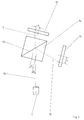
- a first beam splitter on the first frame 1 14 is arranged, on the semi-transparent mirror surface 15 of which the first laser beam 16 horizontally emitted by the rear laser 7 splits into a rectilinearly continuous partial laser beam 17 and into a first partial laser beam 18 reflected along the first frame 1.
- the continuous first laser partial beam 17 strikes a position-sensitive first photodetector 19 arranged behind the beam splitter 14, for example a quadrant diode, and the reflected laser partial beam 18 hits a position-sensitive second photodetector 20 arranged perpendicular to the first photodetector 19 on the first frame 1.
- the laser 7 is firmly positioned in advance at the rear end of the landing gear stand and adjusted with the aid of the two vials 10, 11 arranged on the laser unit 2. Then the first frame 1 is inserted into the receptacles of the front floating plates 3, 4 and also adjusted with the aid of the two first vials 8, 9 arranged on the first frame 1. The front measuring units are then moved up to the probing plates 12, 13 and probed against them. Deviations from the adjusted probe plates 12, 13 are, as shown in FIG. 2, detected on the basis of the points of incidence of the continuous and reflected partial laser beam 17, 18 on the first and second photodetectors 19, 20.
- the track angle ⁇ v and the offset d v in relation to the first laser beam 16 can be calculated from the known geometric arrangement of the photodetectors 19, 20 and the beam splitter 14 and from the distances a, b detected at the two photodetectors 19, 20.
- the measured values are stored as calibration values in a computer and with the track, camber and dachshund run measurements on one Motor vehicle considered.
- the rear measuring units of the landing gear stand are calibrated in the same way after the first frame 1 has been inserted into the corresponding receptacles 57 of the rear floating plates 5, 6 and adjusted.
- the first frame 1 and the laser unit 2 are removed from the chassis position, the motor vehicle to be measured is brought into the chassis position and the vehicle wheels are touched by the four calibrated measuring units, the measurements being based on those in the floating plates 3, 4, 5, 6 existing driving rollers 59 can advantageously also be carried out on running wheels.
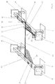
- the device is also composed of two parts: a front and a rear beam-like frame 21, 22, the front frame 21, as already described in FIG. 1, in receptacles of the front floating plates 3, 4 provided for this purpose and the rear frame 22 at the same time in the same way in corresponding receptacles of the rear floating plates 5, 6 of the landing gear stand.
- the front frame 21 has two further outer lasers 25, 26 which emit two further laser beams 27, 28 running parallel to one another and can be aligned horizontally with the aid of further dragonflies 23, 24 arranged perpendicular to one another on its upper side.
- the front frame 21 is provided with a left-hand and a right-hand front probe plate 29, 30, which are parallel to the other laser beams 27, 28 and perpendicular to the first one they span Level 33 are oriented.
- the rear frame 22 also has on its front sides a left-hand and a right-hand rear probe plate 31, 32 and two outer beam splitters 34, 35 assigned to the outer lasers 25, 26, in which the incident outer laser beams 27, 28 pass through them in a straight line split further laser partial beams 36, 37 and into further laser partial beams 38, 39 reflected away from the rear probe plates 31, 32 along the rear frame 22.
- rear probing plates 31, 32 are oriented parallel to the contact surfaces of the inner photodetectors 42, 43 and perpendicular to a second plane 44 spanned by the centers of the outer and inner photodetectors 40, 41, 42, 43 on the rear frame 22.
- the front frame 21 is inserted into receptacles provided for the front floating plates 3, 4 and the rear frame 22 into receptacles provided for the rear floating plates 5, 6.
- the front frame 21 is leveled by means of a height adjustment (not shown) on the front frame while observing the front vials 23, 24 so that the plane 33 spanned by the outer laser beams 27, 28 is aligned horizontally.
- the rear frame 22 is aligned so that the outer laser beams 27, 28 hit the associated beam splitters 34, 35 perpendicularly and through them in a straight line continuous further laser partial beams 36, 37 strike the outer further photodetectors 40, 41 and the reflected further laser partial beams 38, 39 running perpendicular to it along the rear frame 22 hit the inner further photodetectors 42, 43.
- the front and rear frames 21, 22 are arranged in such a way that the left-hand contact plates 29, 31 and the right-hand probing plates 30, 32 are positioned exactly in a vertical plane without a transverse offset.
- the correction values for arithmetic or mechanical correction of the rear probe plates 31, 32 in relation to the front Probe plates 29, 30 delivers.
- the probing plates 29, 30, 31, 32 are touched by the four measuring units of the undercarriage stand and the values measured are stored in the computer as calibration values and taken into account in the measurements of the track, camber and dachshund on a motor vehicle.
- Fig. 4 shows schematically a perspective view of another advantageous embodiment of the device according to the invention, which also consists of two parts: the front and rear frames 21, 22. Instead of the two outer lasers 25, 26 of the second
- the front frame 21 is leveled with the aid of the front vials 23, 24 so that the is aligned horizontally with the further laser beam 46 and the front frame 21, the front probe plates 29, 30 being oriented perpendicular to this plane and parallel to the further laser beam 46.
- the rear frame 22 is aligned horizontally with the aid of the further rear vials 53, 54.
- the fourth plane 55 spanned by the continuous and the reflected further laser partial beam 49, 50 and the third plane 48 spanned by the further laser beam 46 and the front frame 21 then run parallel.
- the third and fourth planes 48, 55 are identical to one another and the left-hand contact plates 29, 31 and the right-hand contact plates 30, 32 are exactly in one plane without transversal Offset positioned.
- Transversal misalignment and rotational deviations with respect to the still remaining rotational degree of freedom of the rear frame 22 are displayed in front of the inner and outer further photodetectors 51, 52 and fed to a computer which relates correction values for arithmetic or mechanical correction of the rear probe plates 31, 32 in relation to the front probing plates 29, 30 provides.
- the probing plates 29, 30, 31, 32 are touched by the four measuring units of the undercarriage stand and the values measured are stored in the computer as calibration values and taken into account in the measurements of the track, camber and dachshund on a motor vehicle.
Landscapes
- Physics & Mathematics (AREA)
- General Physics & Mathematics (AREA)
- Length Measuring Devices By Optical Means (AREA)
- Length Measuring Devices With Unspecified Measuring Means (AREA)
Applications Claiming Priority (2)
| Application Number | Priority Date | Filing Date | Title |
|---|---|---|---|
| DE4234999 | 1992-10-16 | ||
| DE4234999 | 1992-10-16 |
Publications (2)
| Publication Number | Publication Date |
|---|---|
| EP0593066A1 true EP0593066A1 (fr) | 1994-04-20 |
| EP0593066B1 EP0593066B1 (fr) | 1996-12-04 |
Family
ID=6470676
Family Applications (1)
| Application Number | Title | Priority Date | Filing Date |
|---|---|---|---|
| EP93116689A Expired - Lifetime EP0593066B1 (fr) | 1992-10-16 | 1993-10-15 | Dispositif pour calibrer des unités de mesure des angles de chasse, de pincement et d'inclinaison des roues de voitures sur un dispositif support |
Country Status (3)
| Country | Link |
|---|---|
| EP (1) | EP0593066B1 (fr) |
| DE (1) | DE59304664D1 (fr) |
| ES (1) | ES2094447T3 (fr) |
Cited By (20)
| Publication number | Priority date | Publication date | Assignee | Title |
|---|---|---|---|---|
| FR2769365A1 (fr) * | 1997-10-08 | 1999-04-09 | Muller Bem | Dispositif de controle de geometrie a laser |
| WO2004068072A1 (fr) * | 2003-01-27 | 2004-08-12 | Snap-On Technologies, Inc. | Certification d'etalonnage d'un equipement de reglage du parallelisme des roues |
| DE102007024905A1 (de) * | 2007-05-29 | 2008-12-04 | Siemens Ag | Verfahren zur Kalibrierung eines Meßsystems zur Messung der Achsgeometrie eines Fahrzeugs und zugehörige Vorrichtung |
| US7710555B2 (en) | 2006-06-27 | 2010-05-04 | Burke E. Porter Machinery Company | Apparatus and method for determining the orientation of an object such as vehicle wheel alignment |
| US7864309B2 (en) | 2007-05-04 | 2011-01-04 | Burke E. Porter Machinery Company | Non contact wheel alignment sensor and method |
| DE102015101988A1 (de) * | 2015-02-12 | 2016-08-18 | Dr. Ing. H.C. F. Porsche Aktiengesellschaft | Prüfvorrichtung mit einer synthetischen Messsignal-Erzeugungsvorrichtung |
| DE102018212138A1 (de) * | 2018-07-20 | 2020-01-23 | Bayerische Motoren Werke Aktiengesellschaft | Messvorrichtung zum Vermessen von zumindest einem Kraftfahrzeugteil mit zumindest vier Aufnehmern, Verfahren zum Kalibrieren und Verfahren zum Vermessen eines Kraftfahrzeugteils |
| US10551180B2 (en) | 2016-09-30 | 2020-02-04 | Burke E. Porter Marchinery Company | Wheel alignment measurement method and system for vehicle wheels |
| CN111780782A (zh) * | 2020-06-30 | 2020-10-16 | 中国航发南方工业有限公司 | 激光对中仪校准装置 |
| CN113532334A (zh) * | 2021-07-30 | 2021-10-22 | 北京长安汽车工程技术研究有限责任公司 | 一种车辆前束角和外倾角测量装置及方法 |
| US11243074B2 (en) | 2018-04-30 | 2022-02-08 | BPG Sales and Technology Investments, LLC | Vehicle alignment and sensor calibration system |
| CN115144206A (zh) * | 2022-06-30 | 2022-10-04 | 东风汽车集团股份有限公司 | 一种校验靶、基于校验靶的k&c试验方法 |
| US11597091B2 (en) | 2018-04-30 | 2023-03-07 | BPG Sales and Technology Investments, LLC | Robotic target alignment for vehicle sensor calibration |
| US11624608B2 (en) | 2018-04-30 | 2023-04-11 | BPG Sales and Technology Investments, LLC | Vehicular alignment for sensor calibration |
| US11781860B2 (en) | 2018-04-30 | 2023-10-10 | BPG Sales and Technology Investments, LLC | Mobile vehicular alignment for sensor calibration |
| US11835646B2 (en) | 2018-04-30 | 2023-12-05 | BPG Sales and Technology Investments, LLC | Target alignment for vehicle sensor calibration |
| CN118393590A (zh) * | 2024-06-28 | 2024-07-26 | 浙江华视智检科技有限公司 | 一种安检机的能量波动控制方法、装置和计算机设备 |
| US12172654B2 (en) | 2021-01-28 | 2024-12-24 | BPG Sales and Technology Investments, LLC | Target alignment system and method for sensor calibration |
| US12270639B2 (en) | 2020-04-27 | 2025-04-08 | BPG Sales and Technology Investments, LLC | Non-contact vehicle orientation and alignment sensor and method |
| US12385766B2 (en) | 2018-04-30 | 2025-08-12 | BPG Sales and Technology Investments, LLC | Vehicular alignment for sensor calibration |
Citations (4)
| Publication number | Priority date | Publication date | Assignee | Title |
|---|---|---|---|---|
| FR2319141A1 (fr) * | 1975-07-25 | 1977-02-18 | Samefa Ab | Dispositif optique pour la production de faisceaux lumineux exactement perpendiculaires les uns aux autres |
| FR2410249A1 (fr) * | 1977-11-24 | 1979-06-22 | Zeiss Jena Veb Carl | Dispositif permettant d'effectuer simultanement des mesures d'alignement et de direction |
| US4615618A (en) * | 1984-06-21 | 1986-10-07 | Jvi Laser Systems Inc. | Apparatus for determining the relationship of vehicle thrust line, and body center line for use in wheel alignment |
| WO1989004947A1 (fr) * | 1987-11-17 | 1989-06-01 | Axle-Tru, Inc. | Outil portatif d'alignement de chassis et d'essieux |
-
1993
- 1993-10-15 EP EP93116689A patent/EP0593066B1/fr not_active Expired - Lifetime
- 1993-10-15 DE DE59304664T patent/DE59304664D1/de not_active Expired - Fee Related
- 1993-10-15 ES ES93116689T patent/ES2094447T3/es not_active Expired - Lifetime
Patent Citations (4)
| Publication number | Priority date | Publication date | Assignee | Title |
|---|---|---|---|---|
| FR2319141A1 (fr) * | 1975-07-25 | 1977-02-18 | Samefa Ab | Dispositif optique pour la production de faisceaux lumineux exactement perpendiculaires les uns aux autres |
| FR2410249A1 (fr) * | 1977-11-24 | 1979-06-22 | Zeiss Jena Veb Carl | Dispositif permettant d'effectuer simultanement des mesures d'alignement et de direction |
| US4615618A (en) * | 1984-06-21 | 1986-10-07 | Jvi Laser Systems Inc. | Apparatus for determining the relationship of vehicle thrust line, and body center line for use in wheel alignment |
| WO1989004947A1 (fr) * | 1987-11-17 | 1989-06-01 | Axle-Tru, Inc. | Outil portatif d'alignement de chassis et d'essieux |
Cited By (24)
| Publication number | Priority date | Publication date | Assignee | Title |
|---|---|---|---|---|
| FR2769365A1 (fr) * | 1997-10-08 | 1999-04-09 | Muller Bem | Dispositif de controle de geometrie a laser |
| WO2004068072A1 (fr) * | 2003-01-27 | 2004-08-12 | Snap-On Technologies, Inc. | Certification d'etalonnage d'un equipement de reglage du parallelisme des roues |
| US7089776B2 (en) | 2003-01-27 | 2006-08-15 | Snap-On Incorporated | Calibration certification for wheel alignment equipment |
| CN1742193B (zh) * | 2003-01-27 | 2010-04-28 | 斯耐普昂技术有限公司 | 车轮定位设备的校准检定 |
| US7710555B2 (en) | 2006-06-27 | 2010-05-04 | Burke E. Porter Machinery Company | Apparatus and method for determining the orientation of an object such as vehicle wheel alignment |
| US7864309B2 (en) | 2007-05-04 | 2011-01-04 | Burke E. Porter Machinery Company | Non contact wheel alignment sensor and method |
| US8107062B2 (en) | 2007-05-04 | 2012-01-31 | Burke E. Porter Machinery Co. | Non contact wheel alignment sensor and method |
| US8400624B2 (en) | 2007-05-04 | 2013-03-19 | Burke E. Porter Machinery Company | Non contact wheel alignment sensor and method |
| DE102007024905A1 (de) * | 2007-05-29 | 2008-12-04 | Siemens Ag | Verfahren zur Kalibrierung eines Meßsystems zur Messung der Achsgeometrie eines Fahrzeugs und zugehörige Vorrichtung |
| DE102015101988A1 (de) * | 2015-02-12 | 2016-08-18 | Dr. Ing. H.C. F. Porsche Aktiengesellschaft | Prüfvorrichtung mit einer synthetischen Messsignal-Erzeugungsvorrichtung |
| US10551180B2 (en) | 2016-09-30 | 2020-02-04 | Burke E. Porter Marchinery Company | Wheel alignment measurement method and system for vehicle wheels |
| US11781860B2 (en) | 2018-04-30 | 2023-10-10 | BPG Sales and Technology Investments, LLC | Mobile vehicular alignment for sensor calibration |
| US11243074B2 (en) | 2018-04-30 | 2022-02-08 | BPG Sales and Technology Investments, LLC | Vehicle alignment and sensor calibration system |
| US11597091B2 (en) | 2018-04-30 | 2023-03-07 | BPG Sales and Technology Investments, LLC | Robotic target alignment for vehicle sensor calibration |
| US11624608B2 (en) | 2018-04-30 | 2023-04-11 | BPG Sales and Technology Investments, LLC | Vehicular alignment for sensor calibration |
| US11835646B2 (en) | 2018-04-30 | 2023-12-05 | BPG Sales and Technology Investments, LLC | Target alignment for vehicle sensor calibration |
| US12385766B2 (en) | 2018-04-30 | 2025-08-12 | BPG Sales and Technology Investments, LLC | Vehicular alignment for sensor calibration |
| DE102018212138A1 (de) * | 2018-07-20 | 2020-01-23 | Bayerische Motoren Werke Aktiengesellschaft | Messvorrichtung zum Vermessen von zumindest einem Kraftfahrzeugteil mit zumindest vier Aufnehmern, Verfahren zum Kalibrieren und Verfahren zum Vermessen eines Kraftfahrzeugteils |
| US12270639B2 (en) | 2020-04-27 | 2025-04-08 | BPG Sales and Technology Investments, LLC | Non-contact vehicle orientation and alignment sensor and method |
| CN111780782A (zh) * | 2020-06-30 | 2020-10-16 | 中国航发南方工业有限公司 | 激光对中仪校准装置 |
| US12172654B2 (en) | 2021-01-28 | 2024-12-24 | BPG Sales and Technology Investments, LLC | Target alignment system and method for sensor calibration |
| CN113532334A (zh) * | 2021-07-30 | 2021-10-22 | 北京长安汽车工程技术研究有限责任公司 | 一种车辆前束角和外倾角测量装置及方法 |
| CN115144206A (zh) * | 2022-06-30 | 2022-10-04 | 东风汽车集团股份有限公司 | 一种校验靶、基于校验靶的k&c试验方法 |
| CN118393590A (zh) * | 2024-06-28 | 2024-07-26 | 浙江华视智检科技有限公司 | 一种安检机的能量波动控制方法、装置和计算机设备 |
Also Published As
| Publication number | Publication date |
|---|---|
| EP0593066B1 (fr) | 1996-12-04 |
| ES2094447T3 (es) | 1997-01-16 |
| DE59304664D1 (de) | 1997-01-16 |
Similar Documents
| Publication | Publication Date | Title |
|---|---|---|
| EP0593066B1 (fr) | Dispositif pour calibrer des unités de mesure des angles de chasse, de pincement et d'inclinaison des roues de voitures sur un dispositif support | |
| EP2329221B1 (fr) | Système cible, ensemble de systèmes cibles et dispositif de réglage optique de la géométrie | |
| EP3329294B1 (fr) | Procédé et dispositif d'étalonnage de systèmes d'aide de véhicules | |
| DE69706021T2 (de) | Radausrichtung mit beweglicher Video Kamera | |
| DE2633391C2 (de) | Anordnung zur Prüfung oder Ausrichtung rechtwinklig sich schneidender Achsen | |
| EP0842393B1 (fr) | Procede pour aligner des elements entre eux et sonde de mesure de position utilisee a cet effet | |
| DE102018210351B4 (de) | System und Verfahren zum Bestimmen einer Position und/oder Orientierung einer Wechselbrücke in Relation zu einem Fahrzeug | |
| DE3446358C2 (fr) | ||
| DE2923346A1 (de) | Vorrichtung zum messen der einstellung von raedern eines kraftfahrzeugs und verfahren zum einjustieren der vorrichtung auf das fahrzeug | |
| WO2001007862A1 (fr) | Installation permettant de determiner la geometrie d'une roue et/ou d'un essieu de vehicules automobiles | |
| DE3736206A1 (de) | Verfahren und vorrichtung zur pruefung der radausrichtung von fahrzeugen | |
| DE10043354A1 (de) | Fahrwerkvermessungseinrichtung | |
| EP2379982A1 (fr) | Procédé de mesure du châssis et dispositif de mesure de la géométrie du châssis d'un véhicule | |
| EP1969310A2 (fr) | Procédé de mesure optique de châssis | |
| WO2009118211A1 (fr) | Tête de mesure pour un système de réglage de la géométrie d'un véhicule, système de réglage de la géométrie d'un véhicule, ainsi que procédé de détermination des paramètres de position de têtes de mesure d'un système de réglage de la géométrie d'un véhicule | |
| DE102019104466A1 (de) | Vorrichtung zur Kraftfahrzeug-Spurmessung und Verfahren zur Kraftfahrzeug-Spurmessung | |
| EP0593067B1 (fr) | Dispositif et procédé pour la détermination de l'orientation et la position d'objets à l'aide de rayons lasers | |
| DE10050653A1 (de) | Vorrichtung zum Bestimmen der Rad-und/oder Achsgeometrie | |
| DE3116214C2 (de) | Umlenkeinheit | |
| EP0994329A1 (fr) | Etalonnage d'un dispositif pour déterminer l'alignement des roues d'un véhicule | |
| DE69705288T2 (de) | Vorrichtung zum Messen von geometrischen Grössen von Fahrrad- oder Motorradrahmen | |
| DE102011055118A1 (de) | Verfahren zur Bestimmung der Orientierung zweier über zwei Kreuzgelenke und eine dritte Welle verbundener Wellen in der Ebene der drei Wellen | |
| EP0270705B1 (fr) | Dispositif de mesure de l'angle de braquage d'une roue dirigeable d'un véhicule automobile | |
| DE3206646C2 (de) | Radstellungs-Meßvorrichtung | |
| DE3241074A1 (de) | Verfahren zur fehlerkompensation bei dreidimensionalen mess- und/oder anreissgeraeten |
Legal Events
| Date | Code | Title | Description |
|---|---|---|---|
| PUAI | Public reference made under article 153(3) epc to a published international application that has entered the european phase |
Free format text: ORIGINAL CODE: 0009012 |
|
| AK | Designated contracting states |
Kind code of ref document: A1 Designated state(s): BE DE ES FR GB IT PT SE |
|
| 17P | Request for examination filed |
Effective date: 19940926 |
|
| GRAG | Despatch of communication of intention to grant |
Free format text: ORIGINAL CODE: EPIDOS AGRA |
|
| GRAH | Despatch of communication of intention to grant a patent |
Free format text: ORIGINAL CODE: EPIDOS IGRA |
|
| 17Q | First examination report despatched |
Effective date: 19960424 |
|
| RAP1 | Party data changed (applicant data changed or rights of an application transferred) |
Owner name: SCHENCK KOMEG GMBH |
|
| GRAH | Despatch of communication of intention to grant a patent |
Free format text: ORIGINAL CODE: EPIDOS IGRA |
|
| GRAA | (expected) grant |
Free format text: ORIGINAL CODE: 0009210 |
|
| ITF | It: translation for a ep patent filed | ||
| AK | Designated contracting states |
Kind code of ref document: B1 Designated state(s): BE DE ES FR GB IT PT SE |
|
| REF | Corresponds to: |
Ref document number: 59304664 Country of ref document: DE Date of ref document: 19970116 |
|
| REG | Reference to a national code |
Ref country code: ES Ref legal event code: FG2A Ref document number: 2094447 Country of ref document: ES Kind code of ref document: T3 |
|
| ET | Fr: translation filed | ||
| GBT | Gb: translation of ep patent filed (gb section 77(6)(a)/1977) |
Effective date: 19970218 |
|
| REG | Reference to a national code |
Ref country code: PT Ref legal event code: SC4A Free format text: AVAILABILITY OF NATIONAL TRANSLATION Effective date: 19961206 |
|
| PLBE | No opposition filed within time limit |
Free format text: ORIGINAL CODE: 0009261 |
|
| STAA | Information on the status of an ep patent application or granted ep patent |
Free format text: STATUS: NO OPPOSITION FILED WITHIN TIME LIMIT |
|
| 26N | No opposition filed | ||
| PGFP | Annual fee paid to national office [announced via postgrant information from national office to epo] |
Ref country code: PT Payment date: 19990924 Year of fee payment: 7 |
|
| PGFP | Annual fee paid to national office [announced via postgrant information from national office to epo] |
Ref country code: SE Payment date: 19991021 Year of fee payment: 7 |
|
| PGFP | Annual fee paid to national office [announced via postgrant information from national office to epo] |
Ref country code: BE Payment date: 19991022 Year of fee payment: 7 |
|
| PG25 | Lapsed in a contracting state [announced via postgrant information from national office to epo] |
Ref country code: SE Free format text: THE PATENT HAS BEEN ANNULLED BY A DECISION OF A NATIONAL AUTHORITY Effective date: 20001030 |
|
| PG25 | Lapsed in a contracting state [announced via postgrant information from national office to epo] |
Ref country code: BE Free format text: LAPSE BECAUSE OF NON-PAYMENT OF DUE FEES Effective date: 20001031 |
|
| BERE | Be: lapsed |
Owner name: SCHENCK KOMEG G.M.B.H. Effective date: 20001031 |
|
| PG25 | Lapsed in a contracting state [announced via postgrant information from national office to epo] |
Ref country code: PT Free format text: LAPSE BECAUSE OF NON-PAYMENT OF DUE FEES Effective date: 20010430 |
|
| EUG | Se: european patent has lapsed |
Ref document number: 93116689.6 |
|
| REG | Reference to a national code |
Ref country code: GB Ref legal event code: IF02 |
|
| PGFP | Annual fee paid to national office [announced via postgrant information from national office to epo] |
Ref country code: FR Payment date: 20020906 Year of fee payment: 10 |
|
| PGFP | Annual fee paid to national office [announced via postgrant information from national office to epo] |
Ref country code: GB Payment date: 20020916 Year of fee payment: 10 |
|
| PGFP | Annual fee paid to national office [announced via postgrant information from national office to epo] |
Ref country code: ES Payment date: 20021007 Year of fee payment: 10 |
|
| PG25 | Lapsed in a contracting state [announced via postgrant information from national office to epo] |
Ref country code: GB Free format text: LAPSE BECAUSE OF NON-PAYMENT OF DUE FEES Effective date: 20031015 |
|
| PG25 | Lapsed in a contracting state [announced via postgrant information from national office to epo] |
Ref country code: ES Free format text: LAPSE BECAUSE OF NON-PAYMENT OF DUE FEES Effective date: 20031016 |
|
| GBPC | Gb: european patent ceased through non-payment of renewal fee |
Effective date: 20031015 |
|
| PG25 | Lapsed in a contracting state [announced via postgrant information from national office to epo] |
Ref country code: FR Free format text: LAPSE BECAUSE OF NON-PAYMENT OF DUE FEES Effective date: 20040630 |
|
| REG | Reference to a national code |
Ref country code: FR Ref legal event code: ST |
|
| REG | Reference to a national code |
Ref country code: ES Ref legal event code: FD2A Effective date: 20031016 |
|
| PG25 | Lapsed in a contracting state [announced via postgrant information from national office to epo] |
Ref country code: IT Free format text: LAPSE BECAUSE OF NON-PAYMENT OF DUE FEES Effective date: 20051015 |
|
| PGFP | Annual fee paid to national office [announced via postgrant information from national office to epo] |
Ref country code: DE Payment date: 20051020 Year of fee payment: 13 |
|
| PG25 | Lapsed in a contracting state [announced via postgrant information from national office to epo] |
Ref country code: DE Free format text: LAPSE BECAUSE OF NON-PAYMENT OF DUE FEES Effective date: 20070501 |