EP0593149A1 - Tours de contrôle visuel - Google Patents
Tours de contrôle visuel Download PDFInfo
- Publication number
- EP0593149A1 EP0593149A1 EP93304644A EP93304644A EP0593149A1 EP 0593149 A1 EP0593149 A1 EP 0593149A1 EP 93304644 A EP93304644 A EP 93304644A EP 93304644 A EP93304644 A EP 93304644A EP 0593149 A1 EP0593149 A1 EP 0593149A1
- Authority
- EP
- European Patent Office
- Prior art keywords
- windows
- window
- control room
- room
- work station
- Prior art date
- Legal status (The legal status is an assumption and is not a legal conclusion. Google has not performed a legal analysis and makes no representation as to the accuracy of the status listed.)
- Withdrawn
Links
- 230000000007 visual effect Effects 0.000 title claims description 12
- 238000012423 maintenance Methods 0.000 claims 1
- 238000007789 sealing Methods 0.000 abstract description 4
- 239000000463 material Substances 0.000 description 3
- 238000010276 construction Methods 0.000 description 2
- 229920002379 silicone rubber Polymers 0.000 description 2
- 239000004945 silicone rubber Substances 0.000 description 2
- 239000011521 glass Substances 0.000 description 1
- 230000002093 peripheral effect Effects 0.000 description 1
- 239000000126 substance Substances 0.000 description 1
Images


Classifications
-
- E—FIXED CONSTRUCTIONS
- E04—BUILDING
- E04B—GENERAL BUILDING CONSTRUCTIONS; WALLS, e.g. PARTITIONS; ROOFS; FLOORS; CEILINGS; INSULATION OR OTHER PROTECTION OF BUILDINGS
- E04B1/00—Constructions in general; Structures which are not restricted either to walls, e.g. partitions, or floors or ceilings or roofs
- E04B1/34—Extraordinary structures, e.g. with suspended or cantilever parts supported by masts or tower-like structures enclosing elevators or stairs; Features relating to the elastic stability
-
- E—FIXED CONSTRUCTIONS
- E04—BUILDING
- E04H—BUILDINGS OR LIKE STRUCTURES FOR PARTICULAR PURPOSES; SWIMMING OR SPLASH BATHS OR POOLS; MASTS; FENCING; TENTS OR CANOPIES, IN GENERAL
- E04H12/00—Towers; Masts or poles; Chimney stacks; Water-towers; Methods of erecting such structures
-
- E—FIXED CONSTRUCTIONS
- E04—BUILDING
- E04B—GENERAL BUILDING CONSTRUCTIONS; WALLS, e.g. PARTITIONS; ROOFS; FLOORS; CEILINGS; INSULATION OR OTHER PROTECTION OF BUILDINGS
- E04B1/00—Constructions in general; Structures which are not restricted either to walls, e.g. partitions, or floors or ceilings or roofs
- E04B2001/0053—Buildings characterised by their shape or layout grid
- E04B2001/0084—Buildings with non right-angled horizontal layout grid, e.g. triangular or hexagonal
- E04B2001/0092—Small buildings with hexagonal or similar horizontal cross-section
Definitions
- This invention relates to control towers, and primarily to visual control towers for airports where a wide field of view from the control room is essential.
- a visual control tower comprises a support structure and a polygonal control room carried by the support structure, said control room having, at each of at least two sides thereof, a work station for a controller and a window composed of a plurality of planar transparent panels each of which is disposed outwardly of the area enclosed by the support structure and is inclined so as to face outward and downward, each of which windows is arranged to provide for a controller at the work station at said window a lateral field of view of 180° or more through the window, which field is uninterrupted by mullions or other structural supporting elements.
- Said work stations and said windows are preferably disposed at opposite ends of the control room.
- control room has a third and a fourth window disposed at opposite sides of the control room each of which is inclined so as to face outward and downward and extends between the said two windows which are disposed at opposite ends of the control room, each of said third and fourth windows being composed of a plurality of planar transparent panels.
- said third and fourth windows are disposed outwardly of the area enclosed by said support structure and a further work station for a controller is disposed substantially centrally of the length of at least one of said third and fourth windows, the arrangement being such that for a controller at said further work station there is provided a lateral field of view of 180° or more through the window which field is uninterrupted by mullions or other structural supporting elements.
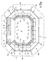
- the control tower 10 comprises a polygonal control room 11 mounted in an elevated position on a support structure generally indicated at 12.
- the support structure includes four support columns 13 which support a roof structure 14 and which jointly define a rectangular area where they extend upward through the control room. As shown in the drawings the upper portions of the columns 13 are inclined and extend parallel to respective adjacent window panels of the control room.
- the outline of the roof structure 14 is shown in chain lines in Figure 1.
- Opposite ends of the control room project outward beyond the said rectangular area defined by columns 13. Outside the rectangular area, at opposite ends of the control room, are two end bays 15 in which central work stations 16 for controllers are provided.
- Each of the end bays 15 has a window formed in several multi-panel sections i.e.
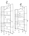
- a three-panel central section 18a, and two two-panel end sections 18b which flank the section 18a at opposite sides respectively, and extend at 45° to the central section, and all the panels of which are inclined so as to face outward and downward at an angle of approximately 15° to the vertical.
- the middle panel of the central section is rectangular and the adjacent panels and all of the panels in the two end sections are trapezoidal.
- the lateral field of view from the central work station or stations 16 at each window 18a, 18b is uninterrupted by mullions or other structural elements where the sections adjoin each other, the joins between panels being sealed by sealing elements 19 made for example from a silicone rubber material which forms only a thin visual line and does not impede lateral vision to a material extent.
- controllers in the two end bays are also forward of the support columns 13 and are thus outside the rectangular area enclosed by the columns, a controller in each of the end bays 15 has an unimpeded lateral field of view of substantially 180°.
- the control tower can be placed so as to enable two runways to be under observation by controllers with a very wide unimpeded lateral field of view from opposite end bays respectively of the control room.
- Multi-panel observation windows 21 and 22 along the third and fourth sides of the control room extend along opposite sides between the two end bays 15 and are glazed in the same manner as the bays 15 using glass panels with sealing elements 19 at the joins.
- a peripheral platform 24 extends along three sides of the room between the windows and the electronic and other control equipment 25 disposed in front of the work stations.
- Platform 24 is at a lower level (eg. 1.2m lower) than the floor of the room to enable technicians to service this equipment without obstructing the field of view of the controllers.
- Platform 24 is reached from the floor of the room by a short downward staircase 26.
- An access staircase 28 to the control room is provided adjacent the observation window 22.
- the columns 30 are therefore well behind controllers at the work stations 16 and provide the controllers with a field of view in excess of 180°.
- This arrangement also makes possible a third work station which can be disposed behind the window 21 extending along the third side of the control room and which provides a field of view in excess of 180° for a controller at this work station.
- all the windows are formed in planar panels and are inclined outward and downward at 15° to the vertical.
- the windows have, neither at or intermediate their ends, any mullions or other supporting structural elements interrupting the field of view.
- the sides of the end panels of the third and fourth windows 21 and 22 are sealed with respect to the adjoining end sections 18b of the first and second windows by sealing elements 19 made from a silicone rubber substance which forms only a thin line and does not impede vision to a material extent.
- sealing elements 19 made from a silicone rubber substance which forms only a thin line and does not impede vision to a material extent.
Landscapes
- Engineering & Computer Science (AREA)
- Architecture (AREA)
- Civil Engineering (AREA)
- Structural Engineering (AREA)
- Physics & Mathematics (AREA)
- Electromagnetism (AREA)
- Load-Bearing And Curtain Walls (AREA)
Applications Claiming Priority (2)
| Application Number | Priority Date | Filing Date | Title |
|---|---|---|---|
| GB9214859 | 1992-07-13 | ||
| GB929214859A GB9214859D0 (en) | 1992-07-13 | 1992-07-13 | Control towers |
Publications (1)
| Publication Number | Publication Date |
|---|---|
| EP0593149A1 true EP0593149A1 (fr) | 1994-04-20 |
Family
ID=10718625
Family Applications (1)
| Application Number | Title | Priority Date | Filing Date |
|---|---|---|---|
| EP93304644A Withdrawn EP0593149A1 (fr) | 1992-07-13 | 1993-06-15 | Tours de contrôle visuel |
Country Status (4)
| Country | Link |
|---|---|
| US (1) | US5396741A (fr) |
| EP (1) | EP0593149A1 (fr) |
| CA (1) | CA2099722A1 (fr) |
| GB (1) | GB9214859D0 (fr) |
Families Citing this family (2)
| Publication number | Priority date | Publication date | Assignee | Title |
|---|---|---|---|---|
| DE20004822U1 (de) * | 2000-03-17 | 2000-05-18 | Wobben, Aloys, 26607 Aurich | Windenergieanlage |
| US8513826B2 (en) * | 2008-06-26 | 2013-08-20 | Ed Mazur | Wind turbine |
Citations (4)
| Publication number | Priority date | Publication date | Assignee | Title |
|---|---|---|---|---|
| GB445426A (en) * | 1934-10-08 | 1936-04-08 | Alfred Charles Morris Jackaman | Improvements relating to buildings, particularly for air ports |
| US3255990A (en) * | 1964-01-27 | 1966-06-14 | Molding Construction Company O | Mold for unitary building structure |
| EP0068735A2 (fr) * | 1981-06-20 | 1983-01-05 | Alan Hilton Ridett | Bâtiment |
| GB2228956A (en) * | 1989-03-07 | 1990-09-12 | Alifabs Ltd | Control room with reduced blind spots |
Family Cites Families (5)
| Publication number | Priority date | Publication date | Assignee | Title |
|---|---|---|---|---|
| US3125189A (en) * | 1964-03-17 | Graham | ||
| US2403369A (en) * | 1943-06-21 | 1946-07-02 | Jr Joseph C Huber | Glass building construction |
| US3246431A (en) * | 1962-10-17 | 1966-04-19 | Faerber Leopold | Building with rotatable observation structure |
| US3584911A (en) * | 1968-12-04 | 1971-06-15 | Air Traffic Control Systems In | Modular mobile air traffic control tower unit and method |
| US5200759A (en) * | 1991-06-03 | 1993-04-06 | Mcginnis Henry J | Telecommunications tower equipment housing |
-
1992
- 1992-07-13 GB GB929214859A patent/GB9214859D0/en active Pending
-
1993
- 1993-06-15 EP EP93304644A patent/EP0593149A1/fr not_active Withdrawn
- 1993-06-21 US US08/078,869 patent/US5396741A/en not_active Expired - Fee Related
- 1993-06-29 CA CA002099722A patent/CA2099722A1/fr not_active Abandoned
Patent Citations (4)
| Publication number | Priority date | Publication date | Assignee | Title |
|---|---|---|---|---|
| GB445426A (en) * | 1934-10-08 | 1936-04-08 | Alfred Charles Morris Jackaman | Improvements relating to buildings, particularly for air ports |
| US3255990A (en) * | 1964-01-27 | 1966-06-14 | Molding Construction Company O | Mold for unitary building structure |
| EP0068735A2 (fr) * | 1981-06-20 | 1983-01-05 | Alan Hilton Ridett | Bâtiment |
| GB2228956A (en) * | 1989-03-07 | 1990-09-12 | Alifabs Ltd | Control room with reduced blind spots |
Non-Patent Citations (1)
| Title |
|---|
| "PADDESTOELKANTOOR", BOUWWERELD, vol. 67, no. 49, 3 December 1971 (1971-12-03), DOETINCHEM,NETHERLANDS, pages 7 * |
Also Published As
| Publication number | Publication date |
|---|---|
| US5396741A (en) | 1995-03-14 |
| CA2099722A1 (fr) | 1994-01-14 |
| GB9214859D0 (en) | 1992-08-26 |
Similar Documents
| Publication | Publication Date | Title |
|---|---|---|
| US6237290B1 (en) | High-rise building with large scale display device inside transparent glass exterior | |
| ES2118527T3 (es) | Dispositivo para rellenar cristales aislantes con gas pesado. | |
| DE69433333D1 (de) | Glasbausteinwand | |
| US5396741A (en) | Visual control towers | |
| ATE134241T1 (de) | Fertigteil-modularbau | |
| CN109296230B (zh) | 一种拼装式变电站整机结构 | |
| GB2284009A (en) | Curtain wall construction | |
| ES2082667T3 (es) | Falso techo suspendido transitable. | |
| EP1810384A1 (fr) | Sous-station de transformation | |
| DE59402106D1 (de) | Fassadenelement | |
| CN218780069U (zh) | 变换停车式防火车库及建筑物 | |
| US5203131A (en) | Structures | |
| CN115370204A (zh) | 一种用于数据中心的预制式方仓、方仓模组及数据中心 | |
| EP0849525A2 (fr) | Lampe encastrée dans le sol. | |
| CN115492433A (zh) | 一种预制舱电气设备模块、预制舱及变电站 | |
| CN217936306U (zh) | 一种通讯工程用通讯柜 | |
| DE59100071D1 (de) | Deckenverkleidung. | |
| KR200494453Y1 (ko) | 복공판 채광창 | |
| EP2522776A2 (fr) | Structure modulaire préfabriquée intégrée pour l'ajustement de la hauteur du sol de quai de gares | |
| CN215107925U (zh) | 一种市政轨道交通机电工程安全防护装置 | |
| SU1709059A1 (ru) | Модульна бурова установка и устройство дл ее монтажа | |
| KR200491921Y1 (ko) | 복공판 채광창 | |
| CN107939095A (zh) | Gis专用防尘棚 | |
| JPH0214503B2 (fr) | ||
| ATE185181T1 (de) | Fassadenelement in form einer rahmenkonstruktion |
Legal Events
| Date | Code | Title | Description |
|---|---|---|---|
| PUAI | Public reference made under article 153(3) epc to a published international application that has entered the european phase |
Free format text: ORIGINAL CODE: 0009012 |
|
| AK | Designated contracting states |
Kind code of ref document: A1 Designated state(s): AT CH DE ES FR GB GR IE IT LI NL PT SE |
|
| 17P | Request for examination filed |
Effective date: 19941005 |
|
| 17Q | First examination report despatched |
Effective date: 19970221 |
|
| STAA | Information on the status of an ep patent application or granted ep patent |
Free format text: STATUS: THE APPLICATION IS DEEMED TO BE WITHDRAWN |
|
| 18D | Application deemed to be withdrawn |
Effective date: 19970803 |