EP0593268A2 - Trépan de forage à molettes - Google Patents
Trépan de forage à molettes Download PDFInfo
- Publication number
- EP0593268A2 EP0593268A2 EP93308134A EP93308134A EP0593268A2 EP 0593268 A2 EP0593268 A2 EP 0593268A2 EP 93308134 A EP93308134 A EP 93308134A EP 93308134 A EP93308134 A EP 93308134A EP 0593268 A2 EP0593268 A2 EP 0593268A2
- Authority
- EP
- European Patent Office
- Prior art keywords
- cutting
- row
- gauge
- rows
- cutter
- Prior art date
- Legal status (The legal status is an assumption and is not a legal conclusion. Google has not performed a legal analysis and makes no representation as to the accuracy of the status listed.)
- Granted
Links
Images

Classifications
-
- E—FIXED CONSTRUCTIONS
- E21—EARTH OR ROCK DRILLING; MINING
- E21B—EARTH OR ROCK DRILLING; OBTAINING OIL, GAS, WATER, SOLUBLE OR MELTABLE MATERIALS OR A SLURRY OF MINERALS FROM WELLS
- E21B10/00—Drill bits
- E21B10/08—Roller bits
- E21B10/16—Roller bits characterised by tooth form or arrangement
-
- E—FIXED CONSTRUCTIONS
- E21—EARTH OR ROCK DRILLING; MINING
- E21B—EARTH OR ROCK DRILLING; OBTAINING OIL, GAS, WATER, SOLUBLE OR MELTABLE MATERIALS OR A SLURRY OF MINERALS FROM WELLS
- E21B10/00—Drill bits
- E21B10/46—Drill bits characterised by wear resisting parts, e.g. diamond inserts
- E21B10/50—Drill bits characterised by wear resisting parts, e.g. diamond inserts the bit being of roller type
- E21B10/52—Drill bits characterised by wear resisting parts, e.g. diamond inserts the bit being of roller type with chisel- or button-type inserts
Definitions
- the invention relates to rolling cutter drill bits for drilling holes in subsurface formations and of the kind comprising a body member, three inwardly facing rolling cutters of generally conical configuration rotatably mounted on the body member, a plurality of cutting inserts arranged in generally circumferential rows around the peripheral surface of each rolling cutter cone, and at least one row of cutting elements on each cone intermeshing with a row on an adjacent cone.
- the invention is an arrangement of cutting inserts upon rows of a soft formation bit which greatly reduces the insert wear and breakage problems associated with bits used for directional drilling, without sacrificing drilling rate.
- a few very hard formation bit designs feature very dense packing of inserts in cones.
- the number of inserts which can be employed is limited only by interference of the recesses which hold the cutting inserts.
- the insert row placement upon any one cone is independent of the other two cones, giving the bit designer considerable freedom in row placement.
- this design allows for a very durable cutting structure, the dense packing of inserts and their limited protrusion cause very slow rates of penetration.
- the diameters of the rolling cones and the protrusions of the inserts must be sized such that one cutter does not interfere with the adjacent cutters. This design is known as an independently rolling or non-intermeshing bit design.
- Non-intermeshed three cone rolling cutter bits are not in common use today.
- the arrangement limits the conglomerate of the three intermeshing cutters to one operative insert row per track along the borehole in the intermeshed area. Although some rows of inserts near the gauge and at the center of the bit are not intermeshed, the placement of all rows upon the cones is heavily influenced by the placement of the intermeshed rows.
- Reaming insert rows are located on the portion of the cone closest to the sidewall of the borehole and closely adjacent to the bit body. These inserts act as necessary to ream the already cut full gage diameter of the borehole well above the bottom of the borehole. Reaming rows of inserts are commonly only slightly protruding and non-intermeshing and are of minimal importance in this specification. Reaming insert rows are shown as numeral 32A in U.S Patent 4,940,099.
- the row of a cone which first engages the uncut full diameter of the borehole is the gauge row.
- Most bits have three gauge rows, one row per cone, which redundantly cut gauge at the same area of the formation.
- the gauge rows are shown as numeral 26 in U.S. Patent 4,611,673.
- Gauge cutting inserts are located on the cones so as to cut the earth formation adjacent to the hole bottom and often cut a portion of the hole bottom in addition to the gauge.
- U.S. Patent 3,452,831 several gauge rows of inserts are indicated. Since only the row of a cone which first engages the formation at the gauge of the borehole is the true gauge row, any other rows on the cone which are placed to cut gauge are reaming already cut formation and act as reaming rows.
- the nose rows of inserts shown as numeral 30 in U.S. Patent 4,611,673, are designed to cut near the center of the borehole. These rows can be, but are not always intermeshed.
- the rows which cut closer to the center of the borehole than the gauge row are collectively called the inner rows of the bit.
- Drill bits often have a plurality of non-intermeshing rows which redundantly cut along the same track of the formation. As far as the formation is concerned this plurality of rows acts as a single operative row.
- An operative row is therefore one or more rows of a drill bit which act to cut substantially a single track along the borehole.
- each operative insert row is dedicated to cut a specific region of the borehole.
- the shape (or profile) at the bottom of the borehole is determined by the arrangements of the operative rows of inserts on the bit and the shapes of the cutting inserts.
- the shape of the borehole has a major influence on the forces imposed on the cutting inserts during drilling and is an important consideration when designing bits for fast penetration and long life. The nomenclature for the various regions of the borehole bottom follows.
- the core region At the center of the borehole is the core region.
- the core is cut by the nose insert rows and is rather easily cut and broken off.
- Concentric to the core is the bottom region of the profile.
- the bottom region is cut by the intermediate rows of the bit.
- the outer edge of the borehole bottom is cut by the row or rows of inserts on the bit with the greatest cutting diameter with respect to the rotational axis of the cone.
- the gage region of the borehole is the cylindrical full diameter surface cut by the gauge and reaming rows of inserts.
- the transition region of the borehole is the narrow ring between the outer edge of the borehole bottom and the gauge.
- An example of a transition region is found in U.S. Patent 2,990,025, figures 2 and 3.
- the tip of the rows containing the insert indicated as numeral 21 have the greatest radial displacement from the cone's centre of rotation of all other rows of the three cones. This intermediate row, therefore, defines the edge of the hole bottom.
- the narrow area between this row and the gauge row indicated as numeral 20 is the transition region of the borehole.
- gauge insert rows are designed. It is important to have as many cutting inserts as possible on the gauge of the bit in order to prolong bit life.
- each cone have a gauge row which acts upon the same portion of gauge of the borehole, redundantly.
- a cone without a gauge row or with a gauge row placed to drill a different portion of the borehole, either closer to or farther from the bottom than the others, will experience different magnitudes and directions of cutting forces. Under certain drilling conditions, this force imbalance can cause the bit's longitudinal axis to orbit about the center of the borehole significantly, a phenomenon called bit gyration. Bit gyration is unacceptable because it causes an uncontrolled hole size to be drilled and it reduces drilling rate.
- the number of inserts that can be placed on either of the interlocked rows is fewer than the number possible without interlocking. Even though interlocking reduces the number of individual gauge inserts possible on a bit, it facilitates close proximity of adjacent operative rows. Most successful prior art bit designs have three intermeshed cutters with at least one and most often two interlocked gauge rows.
- the present invention provides a new drill bit wherein the distribution of the inserts on each rolling cutter is arranged to form a more rounded borehole corner to reduce concentrated side forces and to facilitate directional drilling while minimising gauge wear.
- the invention defines a new category of inner row drilling inserts called the transition or transition row inserts which help drill this rounded corner. These inserts drill neither the gauge of the borehole nor the hole bottom. Rather, transition inserts drill the transition area between the vertical side wall and the borehole bottom.
- the invention also provides for a novel arrangement of borehole corner cutting rows with each row having inserts of a different diameter than the other rows.
- This arrangement concentrates inserts in the transition and gauge areas of the borehole and allows a much higher gauge and transition insert packing density per row than previously possible on interlocked, intermeshed bits.
- Each gauge row cuts at substantially the same portion of the borehole and yet only one gauge row is interlocked.
- the operative gauge row and the closest operative inner row to the gauge i.e. the transition row
- the present invention is defined, in part, in terms of the ratios between certain key dimensions of a rolling cutter drill bit, such ratios being selected to determine the roundness of the corner of the hole being drilled in such manner as to improve the ability of the bit to drill curved boreholes.
- the key dimensions of such drill bit, relevant to the present invention, will now be defined.
- An insert row cutting diameter is defined by the arc swept by the radially outermost cutting tip of an insert of that row as it revolves around the rotational axis of the cone.
- the maximum of the diameters of all rows on all of the rolling cone cutters of the drill bit is designated by the letter c, the maximum cutting diameter. This row cuts the outermost edge of the borehole bottom.
- the maximum of the diameters of all rows that cut gauge on all of the rolling cutters of the drill bit is designated by the letter d, the maximum gauge cutting diameter.
- the rows of inserts are arranged such that the maximum gauge cutting diameter, d, is significantly smaller than the maximum cutting diameter, c. Additionally, at least one transition row of inserts has an intermediate cutting diameter, t, greater than d and less than c.
- a height, h is measured parallel to the longitudinal axis of the bit body and is the distance from the cutting tip of the gauge row of diameter d to the cutting tip of the bottom drilling row of diameter c. Additionally a distance y is measured perpendicular to the longitudinal axis of the bit between the same aforementioned cutting tips.
- h' and y' are the height and distance of the cutting tip of transition row of diameter t from the cutting tip of the gauge row of diameter d.
- the ratio h/c characterises the height of the transition area in a dimensionless manner applicable to any bit size.
- the ratios h/y and h'/y' characterise the slope and curvature of the transition area.
- the combination of ratios h/c, h/y, and h'/y' provide a description of the roundness of the transition area of the borehole, independent of bit size.
- a rolling cutter drill bit comprising: a bit body member; a plurality of rolling cutters each having a cutter body of generally conical configuration rotatably mounted on the bit body member; a plurality of cutting elements arranged in generally circumferential rows around each cutter body, each cutting element comprising a cutting insert located in a socket in the cutter body so as to protrude above the cutter body; the circumferential rows of cutting inserts including at least one bottom cutting row of maximum cutting diameter c, at least one gauge cutting row of gauge cutting diameter d, smaller than diameter c, and at least one transition row of intermediate cutting diameter t, smaller than diameter c and greater than diameter d; and the bottom cutting, gauge cutting, and transition rows of cutting inserts being arranged such that h'/y' is greater than h/y, the dimensions h, y, h' and y' being as hereinbefore defined.
- h/y is in the range from 1 to 1.5, and h/c is greater than .085.
- the invention also provides a rolling cutter drill bit comprising: a bit body member; a plurality of rolling cutters each having a cutter body of generally conical configuration rotatably mounted on the bit body member; a plurality of cutting elements arranged in generally circumferential rows around each cutter body, each cutting element comprising a cutting insert located in a socket in the cutter body so as to protrude above the cutter body; the circumferential rows of cutting elements including at least one gauge cutting row of maximum gauge cutting diameter d and a plurality of operative inner rows each having a cutting diameter; no more than a single gauge cutting row interlocked with an inner row; at least one circumferential inner row of cutting inserts intermeshing with a circumferential inner row of cutting inserts on an adjacent rolling cutter; the gauge cutting row and two adjacent operative inner rows of cutting inserts arranged so that the maximum gauge cutting diameter d is less than the cutting diameters of each of said two adjacent operative inner rows.
- the invention further provides a rolling cutter drill bit for drilling boreholes into earthen formations comprising: a bit body member; a plurality of rolling cutters each having a cutter body of generally conical configuration rotatably mounted on the bit body member; a plurality of cutting elements arranged in generally circumferential rows around each cutter body, each cutting element comprising a generally cylindrical cutting insert of fixed diameter located in a socket in the cutter body so as to protrude above the cutter body; the circumferential rows of cutting elements including a plurality of gauge cutting rows of inserts, one row per rolling cutter, each row orientated to act on the same portion of the earthen formation thereby to act as a single operative row; the cutting inserts in the gauge cutting row of each rolling cutter being of a different diameter from the cutting inserts in the gauge cutting rows of the other rolling cutters.
- the invention further provides a rolling cutter drill bit comprising: a bit body member having a longitudinal axis; a plurality of rolling cutters each having a cutter body of generally conical configuration rotatably mounted on the bit body member; a plurality of cutting elements arranged in generally circumferential rows around each cutter body, each cutting element comprising a cutting insert located in a socket in the cutter body so as to protrude above the cutter body and having an axis extending at a fixed angle with respect to the cutter body; the circumferential rows of cutting inserts including one gauge cutting row and a plurality of inner rows on each rolling cutter, the gauge rows on the plurality of rolling cutters together forming a single operative gauge row; at least one of said circumferential inner rows of cutting inserts intermeshing with a circumferential inner row of cutting inserts on an adjacent rolling cutter; the cutting inserts in said operative gauge row each being orientated at such a fixed angle with respect to its cutter body that its axis is disposed at an angle of between 40° and 70°,
- Each of the cutting inserts in the operative inner row closest to said operative gauge row is preferably orientated at such a fixed angle with respect to its cutter body that its axis is disposed at an angle of between 30° and 45°, and more preferably between 35° and 45°, to the longitudinal axis of the drill bit body member when the insert is in a lowermost position relative to the bit body member.
- Figure 1 depicts an exemplary prior art drill bit, illustrated from a side view.
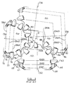
- Figure 2 is an assembly view, showing the intermeshing of the cutting structure on one exemplary prior art bit design.
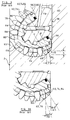
- Figure 3 schematically depicts a composite layout of the same prior art cutting structure shown in Figure 2.
- Figure 3A is a similar view of the area of the rolling cutter shown in Figure 3 adjacent to the borehole bottom and corner.
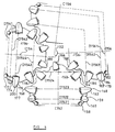
- Figure 4 is an assembly view of a cutting structure for a bit in accordance with the present invention.
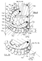
- Figure 5 schematically depicts a composite layout for a bit in accordance with the present invention with the same cutting structure shown in Figure 4.
- Figure 5A is a similar view of the area of the rolling cutter shown in Figure 5 adjacent to the borehole bottom and corner.
- Figure 6 is an enlargement of the area of the rolling cutter adjacent the borehole corner shown in Figure 5.
- Table 1 is a listing of h, c, y, h/y, and h/c for a variety of prior art drill bits, and for exemplary drill bits in accordance with the present invention.
- Drill bit 10 includes a body member, indicated generally at 12, and a plurality of downwardly extending lugs 16a, 16b, and 16c (not visible) which will support each of the rolling cutters, 18, 20 and 22.
- a typical rolling cone cutter 18 includes a conical body 26 which supports a plurality of cutting inserts, indicated generally at 28.
- Cutting inserts 28 will preferably be formed of a hardened material such as tungsten carbide adapted to cut an earthen formation.
- Rolling cone 18 includes inserts 28 arranged in a plurality of rows, indicated generally at 30, 32, and 34.
- Reaming row 30 includes inserts designed to ream the outermost dimension, or the "gauge", of the borehole after this gauge has been cut by the gauge inserts of row 32. Between some rows, for example, between rows 32 and 34, rolling cone 18 includes a peripheral groove 40 to prevent interference and allow intermesh between rolling cone 18 and adjacent rolling cones 20 and 22.
- FIG 2 therein is an assembly view of the structure of one exemplary prior art bit of conventional design.
- the bit shown is a 31 cm (12-1/4'') HP51 manufactured by Reed Tool Co., Houston, Texas.
- the schematic depiction of rolling cone 56 is separated from the rolling cones 52 and 54 to most accurately depict the clearances relative to rolling cones 52 and 54 and the longitudinal axis of the bit 2.
- Rolling cone cutter 52 has five rows of cutting inserts, indicated at 58, 60, 62, 64 and 66.
- the rotational axis of the cone is shown as C52.
- the reaming row 58 has a diameter shown as D521.
- the gauge row 60 has a diameter D522.
- the intermediate row 62 has diameter D523 and so on.
- Rolling cutters 54 and 56 have rows and diameters indicated in a manner similar to cutter 52.
- the diameters are as follows: Cutter 52 Cutter 54 Cutter 56 D521 13.9cm (5.472'') D541 13.9cm (5.472'') D561 13.9cm (5.472'') D522 17.6cm (6.944'') D542 17.6cm (6.944'') D562 17.6cm (6.944'') D523 18.5cm (7.296'') D543 18.5cm (7.296'') D563 17.4cm (6.850'') D524 13.3cm (5.220'') D544 15.6cm (6.148'') D564 10.2cm (4.023'')
- the maximum diameter of a gauge row is 17.6cm (6.944'') on D522, D542 and D562.
- the maximum of all the diameters of the rows on the bit is 18.5cm (7.296'') on D523 and D543.
- the aforementioned maximum cutting diameter c is 18.5cm (7.296'') and the aforementioned maximum gauge cutting diameter d is 17.6cm (6.944").
- FIG 3 herein schematically depicts a composite layout of the same 31cm (12-1/4'') HP51 drill bit as shown in Figure 2.
- the form of the layout shows all rows projected onto one cone generally shown as 90, and acting upon half of the profile of the borehole directly beneath the cone centerline.
- the regions of the borehole cut into the earth 92 by this bit are indicated by 93, 94, 96 and 98.
- the maximum gauge cutting diameter d and the maximum cutting diameter c are both indicated as well as the longitudinal axis 2 of the bit.
- the rows of inserts are arranged such that the borehole formed thereby can be defined by a core region 93, a bottom region 94, a vertical sidewall region 98 and a transition region 96 between bottom and sidewall.
- the relative height of this transition region applicable to any bit size is expressed as a ratio h/c.
- Distance y is the width of the transition region.
- the slope of the transition region is expressed by the ratio h/y.
- the three gauge rows 60, 74 and 84 are exactly overlaying each other. To the formation, these three rows act as a single row. Therefore on this bit the three gauge rows 60, 74, and 84 are collectively called the operative gauge row. In a similar manner, the intermediate rows 62 and 76 overlay each other exactly. These rows are an operative intermediate row.
- FIG. 3A herein is a similar view of the edge of the borehole of the same bit shown in Figure 3.
- the angular orientation 67 of the insert axis of the gauge rows 60, 74, and 84 with respect to the borehole wall is about 33 degrees.
- the axis angle 79 of the inserts on the closest operative inner row to the gauge, rows 62 and 76 is about 22 degrees. Because the inserts are strong in compression and relatively weak in tension, these insert rows on the bit are aligned in generally the same direction as the action of the drilling forces.
- the 33 degree insert axis angle 67 and the 22 degree angle 79 are generally aligned with the average resultant forces from the corner of the borehole applied to the inserts of these rows.
- the loading upon the inserts of these rows is quite different.
- the severe asymmetric insert wear observed on bits used for direction drilling indicates that there are high side forces acting upon the gauge rows and the closest operative inner row to the gauge. Insert wear and breakage on these rows is therefore often severe when these prior art bits are used for directional drilling. Since the bits must be able to drill vertically as well as directionally, if one were to increase the insert orientation angles to make a bit more suitable for directional drilling, gauge insert breakage would become excessive during vertical drilling.
- Table 1 therein is a listing of exemplary prior art bits manufactured by Reed Tool Co. with the values of h, c, and y, and the ratios h/c, and h/y.
- the prior art bits listed in the table are typical for bits which drill more rounded borehole corners than the average commercially available bit. As can be seen, none of these bits has a ratio h/c of greater than .074 combined with a ratio h/y of between 1. and 1.5.
- FIG 4 therein is schematically depicted a cutting structure for a bit in accordance with the present invention.
- Elements in Figures 4, 5, and 5A corresponding to elements in Figures 2, 3 and 3A have corresponding reference numbers, but increased by 100.
- the bit according to the invention thus includes three rolling cone cutters 152, 154, and 156. Again, the schematic depiction of rolling cutter 156 is separated from the rolling cutters 152 and 154 to most accurately depict the clearances relative to rolling cones 152 and 154 and the longitudinal axis of the bit 102.
- Cone 152 has four rows of inserts, indicated at 158, 160, 162 and 164. Cone 152 also includes a nose insert 166. The rotational axis of the cone is shown as C152. Row diameters are defined in the same manner previously described.
- the diameters are as follows: Cutter 152 Cutter 154 Cutter 156 D1521 13.4cm (5.283'') D1541 13.4cm (5.283'') D1561 13.4cm (5.283'') D1522 15.9cm (6.627'') D1542 16.7cm (6.585'') D1562 17.1cm (6.733'') D1523 18.6cm (7.339'') D1543 18.6cm (7.326'') D1563 17.5cm (6.889'') D1524 13.1cm (5.165'') D1544 15.7cm (6.195'')
- the maximum diameter of a gauge row is 17.1cm (6.733'') on D1562.
- each gauge row has a different cutting diameter, each row cuts the same track along the gauge of the borehole.
- the gauge rows 174, 160 and 184 are redundant on the gauge and are therefore a single operative gauge row.
- the maximum of all the diameters of the rows on the bit is 18.6cm (7.339") on D1523.
- the maximum cutting diameter c is 18.6cm (7.339'').
- the maximum gauge cutting diameter d is 17.1cm (6.733'').
- gauge row 174 is fitted with a smaller insert diameter than gauge rows 160 and 184. This allows a greater count of inserts to be placed upon the gauge row 174.
- the row is aligned with the other gauge rows 160 and 184 to cut at the same track of the borehole as shown in Figure 5.
- Gauge row 160 on cone 152 has inserts 159 with an intermediate diameter, larger in diameter than insert 175 and smaller in diameter than gauge row 184 insert 183.
- the insert diameter on row 160 is designed so that there is no need for interlocking with the adjacent row 162.
- Gauge row 184 is also not interlocked.
- the combination of three different insert diameters on the gauge rows of this bit design allow the bit to have maximum insert packing on the three gauge rows. The result is less gauge insert wear and greater gauge insert durability than the prior art gauge row designs.
- FIG. 5 therein is schematically depicted a composite layout of the same bit designed in accordance with the present invention as shown in Figure 4.
- the form is similar to that shown in Figure 3.
- the borehole cut into the earth 192 by this bit indicated by 193, 194, 196 and 198.
- the rows of inserts indicated by 158, 172, 182, 174, 160, 184, 176, 162, 186, 178, 164, 188, 180 and 166 correspond to those indicated in Figure 4.
- the operative reaming row is comprised of individual rows 158, 172 and 182 and the operative gauge row is comprised of rows 174, 160 and 184.
- the maximum gauge cutting diameter d and the maximum cutting diameter c are also both indicated as well as the longitudinal axis 102 of the bit.
- the rows of inserts are arranged such that the borehole formed thereby can be defined by a core region 193, a bottom region 194, a vertical sidewall region 198 and a transition region 196 between bottom and sidewall.
- the transition region of the borehole 168 is between the radially outermost cutting tips on the maximum gauge cutting diameter row(s) and the maximum cutting diameter row(s) as indicated by 170 and 168 respectively. At least one row of transition inserts 176 has a cutting tip 200 which lies within this transition region.
- the ratio h/y should be between 1 and 1.5.
- At least one row of inserts 176 is dedicated to cutting only the transition region 196 of the borehole, as it cuts neither the gauge portion 198 of the borehole nor the bottom portion 194 of the borehole.
- FIG 5A is an enlargement of the area of the rolling cone adjacent the borehole corner and bottom, shown in Figure 5.
- Each cutting insert is located in a socket in its rolling cutter body so as to protrude above the cutter body with its axis extending at a fixed angle with respect to the cutter body.
- the axis of the insert extends at a predetermined angle to the longitudinal axis 102 of the drill bit.
- the insert will extend at a similar angle to the sidewall.
- the cutting inserts in the operative gauge row 160,174,184 are orientated to extend at an angle 167 to the longitudinal axis of the drill bit, when in the lowermost position relative to the drill bit, while the inserts in the operative inner row 176 closest to the gauge extend at an angle 179 to the longitudinal axis.
- the insert orientation angle 167 and 179 which effectively alleviates insert fracture by reducing the degree of misalignment between insert axes and applied directional drilling loads.
- the angle 167 between the axis of the gauge inserts and the sidewall of the formation is between 40 and 70 degrees, and preferably between 50 and 60 degrees.
- the corresponding angle 179 for the inserts of the closest operative inner row to the gauge 176 for the preferred embodiment is between 30 and 45 degrees, and preferably between 35 and 45 degrees.
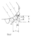
- Figure 6 is an enlargement of the area of the rolling cone adjacent the borehole corner shown in Figure 5.
- the height h and the distance y between the largest gauge cutting diameter d tip 170 and the largest cutting diameter c tip 168 are shown.
- a line 1 is indicated joining points 168 and 170.
- the slope of line 1 is h/y.
- a height h' and the distance y' between the largest gauge cutting diameter d tip 170 and the transition row cutting diameter t tip 200 are shown.
- a line m is indicated joining points 170 and 2000.
- the slope of line m is h'/y'. If point 200 were to lie on line 1 then h'/y' would be equal to h/y.
- the transition row cutting diameter t would have to be increased so that point 200 would not lie on line 1.
- the slope h'/y' is greater than the slope h/y.
- h/y 2.13/1.87 (.840/.737), or 1.139
- h'/y' 1.31/.64 (.516/.251), or 2.055.
- the maximum gauge cutting diameter D1562 will be smaller than the cutting diameters of the next two inner operative rows 176 and 162 of the bit.
- the maximum gauge cutting diameter d In order to provide the cutting diameters c and t as defined above, the maximum gauge cutting diameter d must be smaller than both. Less obvious is the fact that this relationship is novel in three cone bits with intermeshed teeth with only one interlocked gauge row. This novel relationship is due to the manner in which the rows must be arranged (as previously described) to simultaneously: a) intermesh for high drilling penetration rates, b) cut the rounded borehole corner to reduce gauge loading and enhance steerability, and, c) attain maximum gauge insert packing densities possible with minimal interlocking to reduce gauge insert wear.
Landscapes
- Engineering & Computer Science (AREA)
- Life Sciences & Earth Sciences (AREA)
- Geology (AREA)
- Mining & Mineral Resources (AREA)
- Mechanical Engineering (AREA)
- Physics & Mathematics (AREA)
- Environmental & Geological Engineering (AREA)
- Fluid Mechanics (AREA)
- General Life Sciences & Earth Sciences (AREA)
- Geochemistry & Mineralogy (AREA)
- Earth Drilling (AREA)
Applications Claiming Priority (2)
| Application Number | Priority Date | Filing Date | Title |
|---|---|---|---|
| GB9221453 | 1992-10-13 | ||
| GB929221453A GB9221453D0 (en) | 1992-10-13 | 1992-10-13 | Improvements in rolling cutter drill bits |
Publications (3)
| Publication Number | Publication Date |
|---|---|
| EP0593268A2 true EP0593268A2 (fr) | 1994-04-20 |
| EP0593268A3 EP0593268A3 (fr) | 1995-02-08 |
| EP0593268B1 EP0593268B1 (fr) | 1997-03-12 |
Family
ID=10723346
Family Applications (1)
| Application Number | Title | Priority Date | Filing Date |
|---|---|---|---|
| EP93308134A Expired - Lifetime EP0593268B1 (fr) | 1992-10-13 | 1993-10-12 | Trépan de forage à molettes |
Country Status (4)
| Country | Link |
|---|---|
| US (1) | US5372210A (fr) |
| EP (1) | EP0593268B1 (fr) |
| DE (1) | DE69308718D1 (fr) |
| GB (1) | GB9221453D0 (fr) |
Cited By (5)
| Publication number | Priority date | Publication date | Assignee | Title |
|---|---|---|---|---|
| WO1996023954A1 (fr) * | 1995-02-03 | 1996-08-08 | England Richard J | Trepan aleseur spherique |
| GB2327443A (en) * | 1997-06-30 | 1999-01-27 | Smith International | Drill bit with canted gage insert |
| GB2362905A (en) * | 2000-05-18 | 2001-12-05 | Smith International | Earth boring bit |
| GB2368601A (en) * | 2000-11-02 | 2002-05-08 | Baker Hughes Inc | Long barrel inserts for a roller-cone drill bit |
| GB2429221A (en) * | 2005-08-15 | 2007-02-21 | Smith International | Roller cone drill bit |
Families Citing this family (50)
| Publication number | Priority date | Publication date | Assignee | Title |
|---|---|---|---|---|
| US6390210B1 (en) * | 1996-04-10 | 2002-05-21 | Smith International, Inc. | Rolling cone bit with gage and off-gage cutter elements positioned to separate sidewall and bottom hole cutting duty |
| US5881829A (en) * | 1997-07-16 | 1999-03-16 | Baker Hughes Incorporated | Rolling-cutter mining bit with relatively soft formation cutting structure |
| CA2244457C (fr) | 1997-08-05 | 2007-02-20 | Smith International, Inc. | Outil de forage muni d'elements tranchants pour cretes |
| US6095262A (en) * | 1998-08-31 | 2000-08-01 | Halliburton Energy Services, Inc. | Roller-cone bits, systems, drilling methods, and design methods with optimization of tooth orientation |
| US20040045742A1 (en) * | 2001-04-10 | 2004-03-11 | Halliburton Energy Services, Inc. | Force-balanced roller-cone bits, systems, drilling methods, and design methods |
| US20040236553A1 (en) * | 1998-08-31 | 2004-11-25 | Shilin Chen | Three-dimensional tooth orientation for roller cone bits |
| US8437995B2 (en) * | 1998-08-31 | 2013-05-07 | Halliburton Energy Services, Inc. | Drill bit and design method for optimizing distribution of individual cutter forces, torque, work, or power |
| US7334652B2 (en) | 1998-08-31 | 2008-02-26 | Halliburton Energy Services, Inc. | Roller cone drill bits with enhanced cutting elements and cutting structures |
| US20040140130A1 (en) * | 1998-08-31 | 2004-07-22 | Halliburton Energy Services, Inc., A Delaware Corporation | Roller-cone bits, systems, drilling methods, and design methods with optimization of tooth orientation |
| WO2000012859A2 (fr) * | 1998-08-31 | 2000-03-09 | Halliburton Energy Services, Inc. | Trepans a cones, systemes de forage et procedes de forage a forces compensees, et procedes de conception correspondants |
| US20040230413A1 (en) * | 1998-08-31 | 2004-11-18 | Shilin Chen | Roller cone bit design using multi-objective optimization |
| US20030051917A1 (en) * | 1998-08-31 | 2003-03-20 | Halliburton Energy Services, Inc. | Roller cone bits, methods, and systems with anti-tracking variation in tooth orientation |
| AU5798499A (en) | 1998-08-31 | 2000-03-21 | Halliburton Energy Services, Inc. | Roller-cone bits, systems, drilling methods, and design methods with optimization of tooth orientation |
| US6412577B1 (en) * | 1998-08-31 | 2002-07-02 | Halliburton Energy Services Inc. | Roller-cone bits, systems, drilling methods, and design methods with optimization of tooth orientation |
| JP2001117909A (ja) * | 1999-10-21 | 2001-04-27 | Oki Electric Ind Co Ltd | マトリクス形式データの転置回路 |
| US6637527B1 (en) | 2000-06-08 | 2003-10-28 | Smith International, Inc. | Cutting structure for roller cone drill bits |
| US6374930B1 (en) | 2000-06-08 | 2002-04-23 | Smith International, Inc. | Cutting structure for roller cone drill bits |
| US6612384B1 (en) | 2000-06-08 | 2003-09-02 | Smith International, Inc. | Cutting structure for roller cone drill bits |
| US6601660B1 (en) | 2000-06-08 | 2003-08-05 | Smith International, Inc. | Cutting structure for roller cone drill bits |
| US6604587B1 (en) | 2000-06-14 | 2003-08-12 | Smith International, Inc. | Flat profile cutting structure for roller cone drill bits |
| US6530441B1 (en) | 2000-06-27 | 2003-03-11 | Smith International, Inc. | Cutting element geometry for roller cone drill bit |
| US6427792B1 (en) | 2000-07-06 | 2002-08-06 | Camco International (Uk) Limited | Active gauge cutting structure for earth boring drill bits |
| ATE329128T1 (de) | 2000-08-23 | 2006-06-15 | Camco Int Uk Ltd | Indikator für das versagen des lagers eines rollenbohrmeissels |
| US6786288B2 (en) | 2001-08-16 | 2004-09-07 | Smith International, Inc. | Cutting structure for roller cone drill bits |
| US6997273B2 (en) * | 2002-11-15 | 2006-02-14 | Smith International, Inc. | Blunt faced cutter element and enhanced drill bit and cutting structure |
| DE10254942B3 (de) * | 2002-11-25 | 2004-08-12 | Siemens Ag | Verfahren zur automatischen Ermittlung der Koordinaten von Abbildern von Marken in einem Volumendatensatz und medizinische Vorrichtung |
| US6942045B2 (en) * | 2002-12-19 | 2005-09-13 | Halliburton Energy Services, Inc. | Drilling with mixed tooth types |
| US6929079B2 (en) | 2003-02-21 | 2005-08-16 | Smith International, Inc. | Drill bit cutter element having multiple cusps |
| US20060011388A1 (en) * | 2003-01-31 | 2006-01-19 | Mohammed Boudrare | Drill bit and cutter element having multiple extensions |
| US6883624B2 (en) * | 2003-01-31 | 2005-04-26 | Smith International, Inc. | Multi-lobed cutter element for drill bit |
| US7040424B2 (en) * | 2003-03-04 | 2006-05-09 | Smith International, Inc. | Drill bit and cutter having insert clusters and method of manufacture |
| US7195086B2 (en) * | 2004-01-30 | 2007-03-27 | Anna Victorovna Aaron | Anti-tracking earth boring bit with selected varied pitch for overbreak optimization and vibration reduction |
| US7434632B2 (en) | 2004-03-02 | 2008-10-14 | Halliburton Energy Services, Inc. | Roller cone drill bits with enhanced drilling stability and extended life of associated bearings and seals |
| GB2417966A (en) | 2004-08-16 | 2006-03-15 | Halliburton Energy Serv Inc | Roller cone drill bits with optimized bearing structure |
| GB2427633B (en) | 2005-05-17 | 2007-08-15 | Smith International | Drill bit and method of designing a drill bit |
| US7757789B2 (en) * | 2005-06-21 | 2010-07-20 | Smith International, Inc. | Drill bit and insert having bladed interface between substrate and coating |
| GB2443125B (en) | 2005-08-08 | 2012-02-08 | Halliburton Energy Serv Inc | Computer-implemented methods to design a rotary drill bit with a desired bit walk rate |
| US7860693B2 (en) | 2005-08-08 | 2010-12-28 | Halliburton Energy Services, Inc. | Methods and systems for designing and/or selecting drilling equipment using predictions of rotary drill bit walk |
| US7624825B2 (en) * | 2005-10-18 | 2009-12-01 | Smith International, Inc. | Drill bit and cutter element having aggressive leading side |
| US7743855B2 (en) | 2006-09-05 | 2010-06-29 | Smith International, Inc. | Drill bit with cutter element having multifaceted, slanted top cutting surface |
| US20080060852A1 (en) * | 2006-09-07 | 2008-03-13 | Smith International, Inc. | Gage configurations for drill bits |
| US7798258B2 (en) * | 2007-01-03 | 2010-09-21 | Smith International, Inc. | Drill bit with cutter element having crossing chisel crests |
| US7686106B2 (en) * | 2007-01-03 | 2010-03-30 | Smith International, Inc. | Rock bit and inserts with wear relief grooves |
| US8205692B2 (en) * | 2007-01-03 | 2012-06-26 | Smith International, Inc. | Rock bit and inserts with a chisel crest having a broadened region |
| US7631709B2 (en) | 2007-01-03 | 2009-12-15 | Smith International, Inc. | Drill bit and cutter element having chisel crest with protruding pilot portion |
| US7798255B2 (en) * | 2007-01-16 | 2010-09-21 | Smith International, Inc. | Drill bits having optimized cutting element counts for reduced tracking and/or increased drilling performance |
| BRPI0821259A2 (pt) | 2007-12-14 | 2015-06-16 | Halliburton Energy Serv Inc | Métodos e sistemas para prever avanço da broca de perfuração rotativa e para desenhar brocas de pefuração rotativas e outras ferramentas de fundo do poço. |
| US8607899B2 (en) | 2011-02-18 | 2013-12-17 | National Oilwell Varco, L.P. | Rock bit and cutter teeth geometries |
| US20140183798A1 (en) | 2012-12-28 | 2014-07-03 | Smith International, Inc. | Manufacture of cutting elements having lobes |
| CN108474239A (zh) | 2016-01-13 | 2018-08-31 | 斯伦贝谢技术有限公司 | 成角度的凿子插入件 |
Family Cites Families (3)
| Publication number | Priority date | Publication date | Assignee | Title |
|---|---|---|---|---|
| US4611673A (en) * | 1980-03-24 | 1986-09-16 | Reed Rock Bit Company | Drill bit having offset roller cutters and improved nozzles |
| US5224560A (en) * | 1990-10-30 | 1993-07-06 | Modular Engineering | Modular drill bit |
| US5201376A (en) * | 1992-04-22 | 1993-04-13 | Dresser Industries, Inc. | Rock bit with improved gage insert |
-
1992
- 1992-10-13 GB GB929221453A patent/GB9221453D0/en active Pending
-
1993
- 1993-10-12 DE DE69308718T patent/DE69308718D1/de not_active Expired - Lifetime
- 1993-10-12 US US08/136,442 patent/US5372210A/en not_active Expired - Lifetime
- 1993-10-12 EP EP93308134A patent/EP0593268B1/fr not_active Expired - Lifetime
Cited By (12)
| Publication number | Priority date | Publication date | Assignee | Title |
|---|---|---|---|---|
| WO1996023954A1 (fr) * | 1995-02-03 | 1996-08-08 | England Richard J | Trepan aleseur spherique |
| GB2327443A (en) * | 1997-06-30 | 1999-01-27 | Smith International | Drill bit with canted gage insert |
| GB2327443B (en) * | 1997-06-30 | 2001-12-19 | Smith International | Drill bit, cutting insert and method of manufacture |
| GB2362905A (en) * | 2000-05-18 | 2001-12-05 | Smith International | Earth boring bit |
| US6651758B2 (en) | 2000-05-18 | 2003-11-25 | Smith International, Inc. | Rolling cone bit with elements fanned along the gage curve |
| GB2362905B (en) * | 2000-05-18 | 2004-09-15 | Smith International | Earth-boring bit |
| GB2368601A (en) * | 2000-11-02 | 2002-05-08 | Baker Hughes Inc | Long barrel inserts for a roller-cone drill bit |
| US6443246B1 (en) | 2000-11-02 | 2002-09-03 | Baker Hughes Incorporated | Long barrel inserts for earth-boring bit |
| GB2368601B (en) * | 2000-11-02 | 2002-12-31 | Baker Hughes Inc | Long barrel inserts for earth-boring bit |
| GB2429221A (en) * | 2005-08-15 | 2007-02-21 | Smith International | Roller cone drill bit |
| GB2429221B (en) * | 2005-08-15 | 2008-01-02 | Smith International | Drill bit |
| US7370711B2 (en) | 2005-08-15 | 2008-05-13 | Smith International, Inc. | Rolling cone drill bit having non-circumferentially arranged cutter elements |
Also Published As
| Publication number | Publication date |
|---|---|
| GB9221453D0 (en) | 1992-11-25 |
| US5372210A (en) | 1994-12-13 |
| EP0593268A3 (fr) | 1995-02-08 |
| DE69308718D1 (de) | 1997-04-17 |
| EP0593268B1 (fr) | 1997-03-12 |
Similar Documents
| Publication | Publication Date | Title |
|---|---|---|
| EP0593268B1 (fr) | Trépan de forage à molettes | |
| CA1174664A (fr) | Outil a organes de coupe roulants pour la foration dans le roc | |
| US5996713A (en) | Rolling cutter bit with improved rotational stabilization | |
| US6863138B2 (en) | High offset bits with super-abrasive cutters | |
| US7040424B2 (en) | Drill bit and cutter having insert clusters and method of manufacture | |
| US6241034B1 (en) | Cutter element with expanded crest geometry | |
| US5816346A (en) | Rotary drill bits and methods of designing such drill bits | |
| US6367568B2 (en) | Steel tooth cutter element with expanded crest | |
| EP2588704B1 (fr) | Trépans avec caractéristiques anti-suivis | |
| US6176329B1 (en) | Drill bit with ridge-cutting cutter elements | |
| EP0710765A2 (fr) | Perfectionnements relatifs aux trépans de forage rotatifs | |
| US3401759A (en) | Heel pack rock bit | |
| US6651758B2 (en) | Rolling cone bit with elements fanned along the gage curve | |
| US5456328A (en) | Drill bit with improved rolling cutter tooth pattern | |
| EP0962620A2 (fr) | Trépan de forage à deux étages | |
| US5429201A (en) | Drill bit with improved rolling cutter tooth pattern | |
| EP0511547B1 (fr) | Trépan de roche | |
| US2894726A (en) | Drilling bit | |
| US6561292B1 (en) | Rock bit with load stabilizing cutting structure | |
| US7066288B2 (en) | Asymmetric compact for drill bit | |
| US4231438A (en) | Straight hole insert drill bit | |
| US7673709B2 (en) | Earth-boring bit with shear cutting elements | |
| US7096981B2 (en) | Alternating inclinations of compacts for drill bit | |
| CA1071184A (fr) | Jauge entrante asymetrique pour appareil de forage de sol | |
| CA2579636C (fr) | Taillants de geometrie elargie |
Legal Events
| Date | Code | Title | Description |
|---|---|---|---|
| PUAI | Public reference made under article 153(3) epc to a published international application that has entered the european phase |
Free format text: ORIGINAL CODE: 0009012 |
|
| AK | Designated contracting states |
Kind code of ref document: A2 Designated state(s): DE GB IT NL |
|
| RAP3 | Party data changed (applicant data changed or rights of an application transferred) |
Owner name: CAMCO INTERNATIONAL INC. |
|
| RAP1 | Party data changed (applicant data changed or rights of an application transferred) |
Owner name: CAMCO INTERNATIONAL INC. |
|
| PUAL | Search report despatched |
Free format text: ORIGINAL CODE: 0009013 |
|
| AK | Designated contracting states |
Kind code of ref document: A3 Designated state(s): DE GB IT NL |
|
| 17P | Request for examination filed |
Effective date: 19950317 |
|
| 17Q | First examination report despatched |
Effective date: 19951103 |
|
| GRAG | Despatch of communication of intention to grant |
Free format text: ORIGINAL CODE: EPIDOS AGRA |
|
| GRAH | Despatch of communication of intention to grant a patent |
Free format text: ORIGINAL CODE: EPIDOS IGRA |
|
| GRAH | Despatch of communication of intention to grant a patent |
Free format text: ORIGINAL CODE: EPIDOS IGRA |
|
| GRAA | (expected) grant |
Free format text: ORIGINAL CODE: 0009210 |
|
| AK | Designated contracting states |
Kind code of ref document: B1 Designated state(s): DE GB IT NL |
|
| PG25 | Lapsed in a contracting state [announced via postgrant information from national office to epo] |
Ref country code: NL Free format text: LAPSE BECAUSE OF FAILURE TO SUBMIT A TRANSLATION OF THE DESCRIPTION OR TO PAY THE FEE WITHIN THE PRESCRIBED TIME-LIMIT Effective date: 19970312 |
|
| REF | Corresponds to: |
Ref document number: 69308718 Country of ref document: DE Date of ref document: 19970417 |
|
| ITF | It: translation for a ep patent filed | ||
| PG25 | Lapsed in a contracting state [announced via postgrant information from national office to epo] |
Ref country code: DE Effective date: 19970613 |
|
| NLV1 | Nl: lapsed or annulled due to failure to fulfill the requirements of art. 29p and 29m of the patents act | ||
| PLBE | No opposition filed within time limit |
Free format text: ORIGINAL CODE: 0009261 |
|
| 26N | No opposition filed | ||
| REG | Reference to a national code |
Ref country code: GB Ref legal event code: IF02 |
|
| REG | Reference to a national code |
Ref country code: GB Ref legal event code: 732E |
|
| PGFP | Annual fee paid to national office [announced via postgrant information from national office to epo] |
Ref country code: IT Payment date: 20121017 Year of fee payment: 20 Ref country code: GB Payment date: 20121010 Year of fee payment: 20 |
|
| REG | Reference to a national code |
Ref country code: GB Ref legal event code: PE20 Expiry date: 20131011 |
|
| PG25 | Lapsed in a contracting state [announced via postgrant information from national office to epo] |
Ref country code: GB Free format text: LAPSE BECAUSE OF EXPIRATION OF PROTECTION Effective date: 20131011 |