EP0593280A1 - Blowout preventer with tubing shear rams - Google Patents
Blowout preventer with tubing shear rams Download PDFInfo
- Publication number
- EP0593280A1 EP0593280A1 EP93308158A EP93308158A EP0593280A1 EP 0593280 A1 EP0593280 A1 EP 0593280A1 EP 93308158 A EP93308158 A EP 93308158A EP 93308158 A EP93308158 A EP 93308158A EP 0593280 A1 EP0593280 A1 EP 0593280A1
- Authority
- EP
- European Patent Office
- Prior art keywords
- blade
- flat surface
- ram
- shear blade
- shear
- Prior art date
- Legal status (The legal status is an assumption and is not a legal conclusion. Google has not performed a legal analysis and makes no representation as to the accuracy of the status listed.)
- Granted
Links
Images




Classifications
-
- E—FIXED CONSTRUCTIONS
- E21—EARTH OR ROCK DRILLING; MINING
- E21B—EARTH OR ROCK DRILLING; OBTAINING OIL, GAS, WATER, SOLUBLE OR MELTABLE MATERIALS OR A SLURRY OF MINERALS FROM WELLS
- E21B33/00—Sealing or packing boreholes or wells
- E21B33/02—Surface sealing or packing
- E21B33/03—Well heads; Setting-up thereof
- E21B33/06—Blow-out preventers, i.e. apparatus closing around a drill pipe, e.g. annular blow-out preventers
- E21B33/061—Ram-type blow-out preventers, e.g. with pivoting rams
- E21B33/062—Ram-type blow-out preventers, e.g. with pivoting rams with sliding rams
- E21B33/063—Ram-type blow-out preventers, e.g. with pivoting rams with sliding rams for shearing drill pipes
-
- E—FIXED CONSTRUCTIONS
- E21—EARTH OR ROCK DRILLING; MINING
- E21B—EARTH OR ROCK DRILLING; OBTAINING OIL, GAS, WATER, SOLUBLE OR MELTABLE MATERIALS OR A SLURRY OF MINERALS FROM WELLS
- E21B29/00—Cutting or destroying pipes, packers, plugs or wire lines, located in boreholes or wells, e.g. cutting of damaged pipes, of windows; Deforming of pipes in boreholes or wells; Reconditioning of well casings while in the ground
- E21B29/08—Cutting or deforming pipes to control fluid flow
Definitions
- blowout preventers Prior to the present invention blowout preventers have been provided with tubing shear rams, but they were sized to shear a particular size of tubing and they functioned to shear the tubing string so that the upper end of the tubing left in the well bore was flattened and in subsequent operations, in order to be recovered by a fishing operation, had to be cut or otherwise manipulated so that the upper end was open and so that the overshot could properly engage and recover the string.
- US-A-4132266; US-A-4132267; US-A-4341264 and US-A-4531585 are typical examples of such prior tubing shear rams.
- the rams flattened, bent and closed the upper end of the tubing string left in the well bore.
- the blowout preventer was provided with shear rams which were sized to shear a particular size tubing but did not always function properly when shearing smaller or larger tubing strings.
- US-A-4081027 discloses another type of blowout preventer with shear blades, and the upper end of the lower fish is closed by the shearing action as is clearly shown in Fig. 4 of that patent.
- US-A-4240503 discloses a shearing type of blowout preventer with the sealing after cutting being by a seal strip under the upper blade which, when the blades are closed, is caused by the flow of the elastomer responsive to such closing to move into sealing engagement with the upper surface of the lower blade.
- US-A-4537250 discloses a blowout preventer which includes shearing blades with a node or nodes on the lower blade to reduce the shearing force. Also, this patent discloses the use of a concave blade shape to support the string during shearing sufficiently to constrain the string below the upper shear blade as it is sheared to a shape suitable for receiving an overshot type of retrieving tool and to allow flow therein.
- a blowout preventer comprises a body having a central bore therethrough and a pair of opposed guideways extending outwardly from the bore; a ram in each of the guideways; means for moving the rams in the guideways to cause them to move into the bore, in use to shear tubing in the bore, and to withdraw from the bore, each of the rams having coacting upper and lower shearing blades, the ram with the upper shear blade having a front shearing edge and a flat surface extending rearwardly therefrom and terminating in a wall, a recess in the upper shear blade flat surface, a tapered conical recess in the front portion of the upper shear blade above the flat surface, and a tapered conical recess in the lower portion of the upper shear blade below the flat surface; the ram with the lower shear blade having its forward cutting edge positioned to pass immediately under the flat surface on the upper shear blade when the rams are moved together, and a flat surface extending rearward
- the central bore through the body may be provided with opposed guideways extending outward from the vertical bore to house not only the shear rams but any other set of rams which might be desired, such as closing and sealing rams.
- the conical recesses in the shear rams can be sized and positioned to coact to engage a tubing extending through the body bore to cause the upper end of tubing after shearing to leave a substantial opening therein of, e.g. a minimum of 30% of the original flow area within the tubing, and to be no larger in its dimension transversely of the rams than the original diameter of the tubing. Consequently, a separate trip is not required to prepare the upper end of the tubing string left in the well bore prior to lowering an overshot to engage the upper end of such sheared tubing string.
- shear rams which coact when moved into the vertical bore to shear a tubing string positioned in the vertical bore have the capacity to shear tubing strings of different sizes.
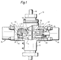
- Blowout preventer 10 shown in FIG. 1 is a prior art blowout preventer having shearing capacities, such as is disclosed and claimed in US-A-4537250.
- Blowout preventer 10 includes body 12 having a central bore 14 extending vertically therethrough and ram guideways 16 which are aligned and extend outwardly through body 12 from opposite sides of bore 14.
- Production tubing string 18 is shown extending through bore 14 in its normal position and with ram assemblies 20 and 22 positioned in their retracted position within guideways 16.
- Production tubing string 18 is supported below blowout preventer 10 in the normal manner so that when it is sheared it does not drop below the blowout preventer 10.
- Suitable means 24 is provided for moving ram assemblies 20 and 22 inwardly and outwardly in their respective guideways 16.
- Such means includes the usual ram piston which is connected to its ram by connecting rod 26.
- Flanges 28 on the ends of connecting rod 26 engage in slots 30 in the rear of ram bodies 32 (lower) and 34 (upper) to provide connection of ram assemblies 20 and 22 to their respective moving means 24.
- Blowout preventer 10 includes shearing means for the cutting of tubing 18, when it is desirable, such as when there is a threatened well blowout.
- the cutting of the tubing with the shearing rams closing and sealing the bore 14 after the shearing provides the means for controlling the well and preventing a blowout.
- Ram assembly 20 shown in the right hand side of the drawing and ram assembly 22 shown in the left hand side of the drawing each include a shear blade.
- Lower shear blade 36 is integral with or (if hardened blades are desired) is secured to the face of body 32 of ram assembly 22 and upper shear blade 38 is a part of or secured to the face of body 34 of ram assembly 20.
- each of ram assemblies 20 and 22 include top seals 40 which are positioned in grooves 42 which extend across the top of ram bodies 32 and 34 from side to side and provide a continuation of side packings on ram bodies 32 and 34.
- Lower shear blade 36 is integral with ram body 32, has a flat upper surface 44 for engaging and sealing against seal element 46 contained within groove 48 in the lower surface 50 of upper shear blade 38.
- the improved blowout preventer of the present invention may be the same as that shown in FIG. 1 with the improved shearing rams 52 and 54 being substituted for the structure shown in FIG. 1.
- Such shearing rams 52 and 54 are positioned within the guideways 16 for reciprocation therein to move into bore 14 to close on and shear string 18 which extends through bore 14 in body 12 and to withdraw from bore 14 into guideways 16.
- Upper shearing ram 52 includes body 56 having rear slot 58 for engagement with connecting rod 26, groove 60 for receiving top seal 40, side recesses 62 for receiving side packers 64 and forwardly extending shearing blade 65 having a cutting edge 66 at its lower portion with flat surface 68 extending rearwardly therefrom.
- Recess 70 in surface 68 is tapered in a direction to reduce its width as it approaches the centre of body 56 as best seen in FIG. 2.
- Recess 70 is provided with side recesses 72 which are sized to receive and retain metal edges 74 of sealing elements 76.
- Flat surface 80 which extends to the front of ram 52 on each side of opening 82 in body 56.
- the forward portion of upper shear blade includes a central tapered conical recess 84 extending upward and of increasing diameter in the upward direction and a flare 86 extending to each side of blade 66 from the conical recess 84.
- Conical tapered recess 88 is positioned centrally in ram body 56 as an extension of wall and functions to receive the upper end of a lower string which has been sheared by the rams 52 and 54.
- Lower shearing ram 54 includes body 90 having rear slot 92 for engagement with connecting rod 26, groove 94 for receiving top seal 40, side recesses 96 for receiving side packers and forwardly extending shearing blade 100 having a cutting edge 102 at its upper front portion with flat surface 104 extending rearwardly therefrom.
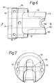
- Flat surface 104 ends in wall 106 which extends upward to the upper surface of body 90 as shown in FIG. 8.
- the forward portion of upper shear blade 100 includes a central tapered conical recess 108 extending upward and of increasing diameter in the downward direction and a flare 110 extending to the side of blade 100 from the conical recess 108.
- Recesses 112 are formed under blade 100 on each side and at its sides blade 100 has a preselected thickness so that it will fit tightly into the space between lower flat surface 68 of upper blade 66 and surface 80 at each side of opening 82. In this manner, blade 100 is supported during shearing so that it does not twist or turn. This ensures that the units will easily and quickly shear a wire line extending through the bore 14 of the blowout preventer 10, even when the wire line is not under tension.
- the sides of tapered conical surface 108 are tapered at 30° adjacent the cutting edge of lower blade and 15° at its lower edge. Similar tapers are provided in tapered conical recess 84 in upper blade. These ramps or tapers leading to the recesses allow tubing of larger sizes to be accommodated and causes the tubing to be centred in the recesses to ensure that it is forced wholly into the recesses and is not flattened during the shearing.
- FIG. 10A and 10B wherein FIG. 10A shows the rounded tubular cross section of a tubing string before shearing and FIG. 10B shows the upper end of the lower fish after it has been sheared.
- the sides of the tubing having been forced inwardly as at 114 and this prevents the tubing from flattening out to a dimension much greater than its original diameter. Also, this allows a very substantial opening as shown in FIG. 10B.
- Requirements of customers who wish to have a tubing shearing ram include that a minimum of 30% of the original flow area inside the tubing be maintained and that the final outside diameter of the lower portion of the sheared tubing be less than or equal to the original diameter of the tubing.
- the crimping of the tubing during shearing eliminates the need for an additional trip downhole to prepare the lower portion of the sheared tubing for an overshot tool and eliminates the need to change out shear blades for each specific tubing size.
- the improved shearing rams of the present invention can handle a variety of sizes of tubing strings, with the samples which have been sheared by these rams running in sizes from 1.75'' to 2'' to 2.38'' with all of the tubing being maintained with a minimum dimension across the shear and having a top opening which is sufficient for circulation therein by an overshot.
- the upper and lower shearing rams are also shown in the perspective views of Figures 11 to 21.
Landscapes
- Life Sciences & Earth Sciences (AREA)
- Engineering & Computer Science (AREA)
- Geology (AREA)
- Mining & Mineral Resources (AREA)
- Physics & Mathematics (AREA)
- Environmental & Geological Engineering (AREA)
- Fluid Mechanics (AREA)
- General Life Sciences & Earth Sciences (AREA)
- Geochemistry & Mineralogy (AREA)
- Shearing Machines (AREA)
- Scissors And Nippers (AREA)
Abstract
Description
- Prior to the present invention blowout preventers have been provided with tubing shear rams, but they were sized to shear a particular size of tubing and they functioned to shear the tubing string so that the upper end of the tubing left in the well bore was flattened and in subsequent operations, in order to be recovered by a fishing operation, had to be cut or otherwise manipulated so that the upper end was open and so that the overshot could properly engage and recover the string.
- US-A-4132266; US-A-4132267; US-A-4341264 and US-A-4531585 are typical examples of such prior tubing shear rams. The rams flattened, bent and closed the upper end of the tubing string left in the well bore. Additionally, the blowout preventer was provided with shear rams which were sized to shear a particular size tubing but did not always function properly when shearing smaller or larger tubing strings. US-A-4081027 discloses another type of blowout preventer with shear blades, and the upper end of the lower fish is closed by the shearing action as is clearly shown in Fig. 4 of that patent. Further, US-A-4240503 discloses a shearing type of blowout preventer with the sealing after cutting being by a seal strip under the upper blade which, when the blades are closed, is caused by the flow of the elastomer responsive to such closing to move into sealing engagement with the upper surface of the lower blade.
- US-A-4537250 discloses a blowout preventer which includes shearing blades with a node or nodes on the lower blade to reduce the shearing force. Also, this patent discloses the use of a concave blade shape to support the string during shearing sufficiently to constrain the string below the upper shear blade as it is sheared to a shape suitable for receiving an overshot type of retrieving tool and to allow flow therein.
- According to the present invention, a blowout preventer comprises a body having a central bore therethrough and a pair of opposed guideways extending outwardly from the bore; a ram in each of the guideways; means for moving the rams in the guideways to cause them to move into the bore, in use to shear tubing in the bore, and to withdraw from the bore, each of the rams having coacting upper and lower shearing blades, the ram with the upper shear blade having a front shearing edge and a flat surface extending rearwardly therefrom and terminating in a wall, a recess in the upper shear blade flat surface, a tapered conical recess in the front portion of the upper shear blade above the flat surface, and a tapered conical recess in the lower portion of the upper shear blade below the flat surface; the ram with the lower shear blade having its forward cutting edge positioned to pass immediately under the flat surface on the upper shear blade when the rams are moved together, and a flat surface extending rearwardly from its cutting edge to provide a sealing surface, a tapered conical recess in the blade extending below the sealing surface; and sealing means positioned in the recess of the upper shear blade flat surface for sealing against the flat surface on the lower shear blade.
- The central bore through the body may be provided with opposed guideways extending outward from the vertical bore to house not only the shear rams but any other set of rams which might be desired, such as closing and sealing rams.
- In use, the conical recesses in the shear rams can be sized and positioned to coact to engage a tubing extending through the body bore to cause the upper end of tubing after shearing to leave a substantial opening therein of, e.g. a minimum of 30% of the original flow area within the tubing, and to be no larger in its dimension transversely of the rams than the original diameter of the tubing. Consequently, a separate trip is not required to prepare the upper end of the tubing string left in the well bore prior to lowering an overshot to engage the upper end of such sheared tubing string.
- The shear rams which coact when moved into the vertical bore to shear a tubing string positioned in the vertical bore have the capacity to shear tubing strings of different sizes.
- In the accompanying drawings:-
- FIG. 1 is a vertical sectional view of a blowout preventer of the kind to which the invention may be applied;
- FIG. 2 is a plan of the upper shear ram of a blowout preventer according to the present invention;
- FIG. 3 is a front view of the upper shear ram shown in FIG. 2;
- FIG. 4 is a side view of the upper shear ram shown in FIGS. 2 and 3;
- FIG. 5 is a section taken on the line 5 - 5 in FIG. 2;
- FIG. 6 is a plan of the lower shear ram of the blowout preventer according to the present invention;
- FIG. 7 is a front view of the lower shear ram shown in FIG. 5;
- FIG. 8 is a side view of the lower shear ram shown in FIGS. 5 and 6;
- FIG. 9 is a section taken on the line 9 - 9 in FIG. 6;
- FIG. 10 are sections of the tubing before (FIG. 10A) and after (FIG. 10B) shearing by the shearing rams of the blowout preventer according to the present invention;
- FIG. 11 is a perspective top view of the upper ram;
- FIG. 12 is a perspective bottom view of the upper ram;
- FIG. 13 is a perspective front view of the upper ram;
- FIG. 14 is a perspective side view of the top ram;
- FIG. 15 is a perspective top view of the lower ram;
- FIG. 16 is a perspective bottom view of the lower ram;
- FIG. 17 is a perspective front view of the lower ram;
- FIG. 18 is a perspective side view of the lower ram;
- FIG. 19 is a perspective top view of the two rams engaged;
- FIG. 20 is a perspective bottom view of the two rams engaged; and,
- FIG. 21 is a perspective side of the two rams engaged.
-
Blowout preventer 10 shown in FIG. 1 is a prior art blowout preventer having shearing capacities, such as is disclosed and claimed in US-A-4537250.Blowout preventer 10 includesbody 12 having acentral bore 14 extending vertically therethrough andram guideways 16 which are aligned and extend outwardly throughbody 12 from opposite sides ofbore 14.Production tubing string 18 is shown extending throughbore 14 in its normal position and withram assemblies guideways 16.Production tubing string 18 is supported belowblowout preventer 10 in the normal manner so that when it is sheared it does not drop below theblowout preventer 10.Suitable means 24 is provided for movingram assemblies respective guideways 16. Such means (not shown in section) includes the usual ram piston which is connected to its ram by connectingrod 26.Flanges 28 on the ends of connectingrod 26 engage inslots 30 in the rear of ram bodies 32 (lower) and 34 (upper) to provide connection ofram assemblies respective moving means 24. -
Blowout preventer 10 includes shearing means for the cutting oftubing 18, when it is desirable, such as when there is a threatened well blowout. The cutting of the tubing with the shearing rams closing and sealing thebore 14 after the shearing provides the means for controlling the well and preventing a blowout.Ram assembly 20 shown in the right hand side of the drawing andram assembly 22 shown in the left hand side of the drawing each include a shear blade. Lower shear blade 36 is integral with or (if hardened blades are desired) is secured to the face ofbody 32 ofram assembly 22 andupper shear blade 38 is a part of or secured to the face ofbody 34 ofram assembly 20. - In addition to
shear blades 36 and 38, each ofram assemblies top seals 40 which are positioned ingrooves 42 which extend across the top ofram bodies ram bodies ram body 32, has a flat upper surface 44 for engaging and sealing against seal element 46 contained within groove 48 in the lower surface 50 ofupper shear blade 38. For additional details of such prior art structure, reference is made to the above mentioned patent. - The improved blowout preventer of the present invention may be the same as that shown in FIG. 1 with the improved
shearing rams rams guideways 16 for reciprocation therein to move intobore 14 to close on andshear string 18 which extends throughbore 14 inbody 12 and to withdraw frombore 14 intoguideways 16. Upper shearingram 52 includesbody 56 havingrear slot 58 for engagement with connectingrod 26,groove 60 for receivingtop seal 40, side recesses 62 for receivingside packers 64 and forwardly extendingshearing blade 65 having acutting edge 66 at its lower portion withflat surface 68 extending rearwardly therefrom. Recess 70 insurface 68 is tapered in a direction to reduce its width as it approaches the centre ofbody 56 as best seen in FIG. 2.Recess 70 is provided withside recesses 72 which are sized to receive and retainmetal edges 74 ofsealing elements 76.Flat surface 80 which extends to the front ofram 52 on each side of opening 82 inbody 56. The forward portion of upper shear blade includes a central taperedconical recess 84 extending upward and of increasing diameter in the upward direction and aflare 86 extending to each side ofblade 66 from theconical recess 84. Conicaltapered recess 88 is positioned centrally inram body 56 as an extension of wall and functions to receive the upper end of a lower string which has been sheared by therams - Lower shearing
ram 54 includesbody 90 havingrear slot 92 for engagement with connectingrod 26,groove 94 for receivingtop seal 40,side recesses 96 for receiving side packers and forwardly extendingshearing blade 100 having acutting edge 102 at its upper front portion withflat surface 104 extending rearwardly therefrom.Flat surface 104 ends inwall 106 which extends upward to the upper surface ofbody 90 as shown in FIG. 8. The forward portion ofupper shear blade 100 includes a central taperedconical recess 108 extending upward and of increasing diameter in the downward direction and aflare 110 extending to the side ofblade 100 from theconical recess 108.Recesses 112 are formed underblade 100 on each side and at itssides blade 100 has a preselected thickness so that it will fit tightly into the space between lowerflat surface 68 ofupper blade 66 andsurface 80 at each side ofopening 82. In this manner,blade 100 is supported during shearing so that it does not twist or turn. This ensures that the units will easily and quickly shear a wire line extending through thebore 14 of theblowout preventer 10, even when the wire line is not under tension. As can be seen from FIG. 6, the sides of taperedconical surface 108 are tapered at 30° adjacent the cutting edge of lower blade and 15° at its lower edge. Similar tapers are provided in taperedconical recess 84 in upper blade. These ramps or tapers leading to the recesses allow tubing of larger sizes to be accommodated and causes the tubing to be centred in the recesses to ensure that it is forced wholly into the recesses and is not flattened during the shearing. - Also, when the improved shear rams 52 and 54 of the present invention shear a string of production tubing, they will cause the upper end of the lower sheared fish to be formed into an opening having a figure of eight shape. This is because of the tapered
conical recess 108 in lower blade and the taperedconical recess 88 inupper blade 66. This is demonstrated in FIG. 10A and 10B wherein FIG. 10A shows the rounded tubular cross section of a tubing string before shearing and FIG. 10B shows the upper end of the lower fish after it has been sheared. The sides of the tubing having been forced inwardly as at 114 and this prevents the tubing from flattening out to a dimension much greater than its original diameter. Also, this allows a very substantial opening as shown in FIG. 10B. - Requirements of customers who wish to have a tubing shearing ram include that a minimum of 30% of the original flow area inside the tubing be maintained and that the final outside diameter of the lower portion of the sheared tubing be less than or equal to the original diameter of the tubing. The crimping of the tubing during shearing eliminates the need for an additional trip downhole to prepare the lower portion of the sheared tubing for an overshot tool and eliminates the need to change out shear blades for each specific tubing size.
- The improved shearing rams of the present invention can handle a variety of sizes of tubing strings, with the samples which have been sheared by these rams running in sizes from 1.75'' to 2'' to 2.38'' with all of the tubing being maintained with a minimum dimension across the shear and having a top opening which is sufficient for circulation therein by an overshot.
- The upper and lower shearing rams are also shown in the perspective views of Figures 11 to 21.
Claims (3)
- A blowout preventer comprising a body (12) having a central bore (14) therethrough and a pair of opposed guideways (16) extending outwardly from the bore; a ram (52,54) in each of the guideways; means (24) for moving the rams in the guideways to cause them to move into the bore, in use to shear tubing in the bore, and to withdraw from the bore, each of the rams having coacting upper and lower shearing blades (65,100), the ram (52) with the upper shear blade (65) having a front shearing edge (66) and a flat surface (68) extending rearwardly therefrom and terminating in a wall (78), a recess (70) in the upper shear blade flat surface, a tapered conical recess (84) in the front portion of the upper shear blade above the flat surface, and a tapered conical recess (88) in the lower portion of the upper shear blade below the flat surface; the ram (54) with the lower shear blade (100) having its forward cutting edge (102) positioned to pass immediately under the flat surface (68) on the upper shear blade when the rams are moved together, and a flat surface (100) extending rearwardly from its cutting edge to provide a sealing surface, a tapered conical recess (108) in the blade extending below the sealing surface; and sealing means (76) positioned in the recess (70) of the upper shear blade flat surface for sealing against the flat surface (108) on the lower shear blade.
- A blowout preventer according to claim 1, including flared surfaces (86,110) on each side of each of the tapered conical recesses (84,108).
- A blowout preventer according to claim 1 or claim 2, including a pair of surfaces (80) spaced apart and spaced below the upper blade flat surface (68) a distance allowing entry of the lower shear blade (100) therebetween.
Applications Claiming Priority (2)
| Application Number | Priority Date | Filing Date | Title |
|---|---|---|---|
| US960690 | 1992-10-14 | ||
| US07/960,690 US5360061A (en) | 1992-10-14 | 1992-10-14 | Blowout preventer with tubing shear rams |
Publications (2)
| Publication Number | Publication Date |
|---|---|
| EP0593280A1 true EP0593280A1 (en) | 1994-04-20 |
| EP0593280B1 EP0593280B1 (en) | 1996-06-19 |
Family
ID=25503487
Family Applications (1)
| Application Number | Title | Priority Date | Filing Date |
|---|---|---|---|
| EP93308158A Expired - Lifetime EP0593280B1 (en) | 1992-10-14 | 1993-10-13 | Blowout preventer with tubing shear rams |
Country Status (4)
| Country | Link |
|---|---|
| US (1) | US5360061A (en) |
| EP (1) | EP0593280B1 (en) |
| CA (1) | CA2106920A1 (en) |
| DE (1) | DE69303248T2 (en) |
Cited By (4)
| Publication number | Priority date | Publication date | Assignee | Title |
|---|---|---|---|---|
| GB2284840A (en) * | 1993-12-08 | 1995-06-21 | Varco Shaffer Inc | Improvements in or relating to oilfield tubular shear ram and method for blowout prevention |
| EP1132566A3 (en) * | 2000-03-07 | 2002-12-04 | Cooper Cameron Corporation | Double shearing rams for ram type blowout preventer |
| WO2007122365A1 (en) * | 2006-04-25 | 2007-11-01 | National Oilwell Varco, L.P. | Apparatus and method for severing a wellbore tubular |
| EP1781897A4 (en) * | 2004-07-27 | 2008-01-23 | T 3 Property Holdings Inc | SHEARING AND SEALING JAR |
Families Citing this family (32)
| Publication number | Priority date | Publication date | Assignee | Title |
|---|---|---|---|---|
| US6173770B1 (en) | 1998-11-20 | 2001-01-16 | Hydril Company | Shear ram for ram-type blowout preventer |
| US6158505A (en) * | 1999-08-30 | 2000-12-12 | Cooper Cameron Corporation | Blade seal for a shearing blind ram in a ram type blowout preventer |
| US7086467B2 (en) * | 2001-12-17 | 2006-08-08 | Schlumberger Technology Corporation | Coiled tubing cutter |
| NO316189B1 (en) * | 2002-01-16 | 2003-12-22 | Norsk Hydro As | Riser control device |
| US6719042B2 (en) | 2002-07-08 | 2004-04-13 | Varco Shaffer, Inc. | Shear ram assembly |
| US7354026B2 (en) * | 2004-08-17 | 2008-04-08 | Cameron International Corporation | Unitary blade seal for a shearing blind ram in a ram type blowout preventer |
| US7703739B2 (en) * | 2004-11-01 | 2010-04-27 | Hydril Usa Manufacturing Llc | Ram BOP shear device |
| US7234530B2 (en) * | 2004-11-01 | 2007-06-26 | Hydril Company Lp | Ram BOP shear device |
| US20060144586A1 (en) * | 2004-12-30 | 2006-07-06 | Cooper Cameron Corporation | Shearing blind ram assembly with a fish pocket |
| US7331562B2 (en) * | 2005-11-07 | 2008-02-19 | Varco I/P, Inc. | Blowout preventer with breech assembly |
| US8720564B2 (en) * | 2006-04-25 | 2014-05-13 | National Oilwell Varco, L.P. | Tubular severing system and method of using same |
| US8424607B2 (en) | 2006-04-25 | 2013-04-23 | National Oilwell Varco, L.P. | System and method for severing a tubular |
| US8720565B2 (en) * | 2006-04-25 | 2014-05-13 | National Oilwell Varco, L.P. | Tubular severing system and method of using same |
| US20080105436A1 (en) * | 2006-11-02 | 2008-05-08 | Schlumberger Technology Corporation | Cutter Assembly |
| US8740174B2 (en) * | 2006-12-12 | 2014-06-03 | Hydril Usa Manufacturing Llc | Dual-direction ram-type blowout preventer seal |
| US7832480B1 (en) | 2008-07-08 | 2010-11-16 | Fanguy Robert P | Apparatus and method for extracting a tubular string from a bore hole |
| US8844898B2 (en) | 2009-03-31 | 2014-09-30 | National Oilwell Varco, L.P. | Blowout preventer with ram socketing |
| US8567490B2 (en) | 2009-06-19 | 2013-10-29 | National Oilwell Varco, L.P. | Shear seal blowout preventer |
| RU2559238C2 (en) | 2010-05-28 | 2015-08-10 | НЭШНЛ ОЙЛВЕЛЛ ВАРКО, Эл.Пи. | Pipe cutting system and method of its application |
| US8540017B2 (en) | 2010-07-19 | 2013-09-24 | National Oilwell Varco, L.P. | Method and system for sealing a wellbore |
| US8544538B2 (en) | 2010-07-19 | 2013-10-01 | National Oilwell Varco, L.P. | System and method for sealing a wellbore |
| US8162046B2 (en) | 2010-08-17 | 2012-04-24 | T-3 Property Holdings, Inc. | Blowout preventer with shearing blades |
| US8807219B2 (en) | 2010-09-29 | 2014-08-19 | National Oilwell Varco, L.P. | Blowout preventer blade assembly and method of using same |
| KR20150092371A (en) | 2011-03-09 | 2015-08-12 | 내셔널 오일웰 바르코 엘.피. | Method and apparatus for sealing a wellbore |
| BR112015020108B1 (en) | 2013-02-21 | 2021-11-09 | National Oilwell Varco, L.P. | ERUPTION PREVENTIVE CONTROLLER UNIT, E, METHOD OF MONITORING AN ERUPTION PREVENTIVE CONTROLLER |
| US9249643B2 (en) | 2013-03-15 | 2016-02-02 | National Oilwell Varco, L.P. | Blowout preventer with wedge ram assembly and method of using same |
| GB201310613D0 (en) * | 2013-06-14 | 2013-07-31 | Enovate Systems Ltd | Well bore control system |
| US9879498B2 (en) * | 2015-04-21 | 2018-01-30 | Axon Pressure Products, Inc. | Shear block design for blowout preventer |
| WO2017039740A1 (en) * | 2015-09-01 | 2017-03-09 | Cameron International Corporation | Blowout preventer including blind seal assembly |
| GB201614712D0 (en) | 2016-08-31 | 2016-10-12 | Enovate Systems Ltd | Improved shear blade |
| EP3533966B1 (en) * | 2018-03-01 | 2022-11-16 | Enovate Systems Limited | Improved shear blade |
| CN119933573B (en) * | 2025-04-08 | 2025-11-28 | 江苏益马机械有限公司 | A blowout preventer hydraulic actuator |
Citations (6)
| Publication number | Priority date | Publication date | Assignee | Title |
|---|---|---|---|---|
| US4081027A (en) * | 1976-08-23 | 1978-03-28 | The Rucker Company | Shear rams for hydrogen sulfide service |
| US4132267A (en) * | 1978-04-06 | 1979-01-02 | Cameron Iron Works, Inc. | Pipe shearing ram assembly for blowout preventer |
| US4132266A (en) * | 1978-04-06 | 1979-01-02 | Cameron Iron Works, Inc. | Pipe shearing ram assembly for blowout preventer |
| US4240503A (en) * | 1979-05-01 | 1980-12-23 | Hydril Company | Blowout preventer shearing and sealing rams |
| US4341264A (en) * | 1980-10-15 | 1982-07-27 | Cameron Iron Works, Inc. | Wellhead shearing apparatus |
| US4537250A (en) * | 1983-12-14 | 1985-08-27 | Cameron Iron Works, Inc. | Shearing type blowout preventer |
Family Cites Families (9)
| Publication number | Priority date | Publication date | Assignee | Title |
|---|---|---|---|---|
| US2919111A (en) * | 1955-12-30 | 1959-12-29 | California Research Corp | Shearing device and method for use in well drilling |
| US3561526A (en) * | 1969-09-03 | 1971-02-09 | Cameron Iron Works Inc | Pipe shearing ram assembly for blowout preventer |
| US4132265A (en) * | 1978-04-06 | 1979-01-02 | Cameron Iron Works, Inc. | Pipe shearing ram assembly for blowout preventer |
| US4313496A (en) * | 1980-04-22 | 1982-02-02 | Cameron Iron Works, Inc. | Wellhead shearing apparatus |
| US4347898A (en) * | 1980-11-06 | 1982-09-07 | Cameron Iron Works, Inc. | Shear ram blowout preventer |
| US4531585A (en) * | 1983-09-12 | 1985-07-30 | Asger Hansen | Safety shear apparatus and method for production wells |
| US4646825A (en) * | 1986-01-02 | 1987-03-03 | Winkle Denzal W Van | Blowout preventer, shear ram, shear blade and seal therefor |
| US4923005A (en) * | 1989-01-05 | 1990-05-08 | Otis Engineering Corporation | System for handling reeled tubing |
| US5199493A (en) * | 1991-05-03 | 1993-04-06 | Sodder George Jr | Methods and apparatus for shutting a conduit |
-
1992
- 1992-10-14 US US07/960,690 patent/US5360061A/en not_active Expired - Lifetime
-
1993
- 1993-09-24 CA CA002106920A patent/CA2106920A1/en not_active Abandoned
- 1993-10-13 EP EP93308158A patent/EP0593280B1/en not_active Expired - Lifetime
- 1993-10-13 DE DE69303248T patent/DE69303248T2/en not_active Expired - Fee Related
Patent Citations (6)
| Publication number | Priority date | Publication date | Assignee | Title |
|---|---|---|---|---|
| US4081027A (en) * | 1976-08-23 | 1978-03-28 | The Rucker Company | Shear rams for hydrogen sulfide service |
| US4132267A (en) * | 1978-04-06 | 1979-01-02 | Cameron Iron Works, Inc. | Pipe shearing ram assembly for blowout preventer |
| US4132266A (en) * | 1978-04-06 | 1979-01-02 | Cameron Iron Works, Inc. | Pipe shearing ram assembly for blowout preventer |
| US4240503A (en) * | 1979-05-01 | 1980-12-23 | Hydril Company | Blowout preventer shearing and sealing rams |
| US4341264A (en) * | 1980-10-15 | 1982-07-27 | Cameron Iron Works, Inc. | Wellhead shearing apparatus |
| US4537250A (en) * | 1983-12-14 | 1985-08-27 | Cameron Iron Works, Inc. | Shearing type blowout preventer |
Cited By (7)
| Publication number | Priority date | Publication date | Assignee | Title |
|---|---|---|---|---|
| GB2284840A (en) * | 1993-12-08 | 1995-06-21 | Varco Shaffer Inc | Improvements in or relating to oilfield tubular shear ram and method for blowout prevention |
| GB2284840B (en) * | 1993-12-08 | 1997-05-07 | Varco Shaffer Inc | Improvements in or relating to oilfield tubular shear ram and method for blowout prevention |
| EP1132566A3 (en) * | 2000-03-07 | 2002-12-04 | Cooper Cameron Corporation | Double shearing rams for ram type blowout preventer |
| EP1781897A4 (en) * | 2004-07-27 | 2008-01-23 | T 3 Property Holdings Inc | SHEARING AND SEALING JAR |
| WO2007122365A1 (en) * | 2006-04-25 | 2007-11-01 | National Oilwell Varco, L.P. | Apparatus and method for severing a wellbore tubular |
| RU2401935C2 (en) * | 2006-04-25 | 2010-10-20 | НЭШНЛ ОЙЛВЕЛЛ ВАРКО, Эл.Пи. | Device and procedure for cutting pipe of well bore |
| EP2400109A3 (en) * | 2006-04-25 | 2012-01-04 | National Oilwell Varco, L.P. | Apparatus and method for severing a wellbore tubular |
Also Published As
| Publication number | Publication date |
|---|---|
| DE69303248T2 (en) | 1996-10-31 |
| DE69303248D1 (en) | 1996-07-25 |
| EP0593280B1 (en) | 1996-06-19 |
| CA2106920A1 (en) | 1994-04-15 |
| US5360061A (en) | 1994-11-01 |
Similar Documents
| Publication | Publication Date | Title |
|---|---|---|
| EP0593280B1 (en) | Blowout preventer with tubing shear rams | |
| US4537250A (en) | Shearing type blowout preventer | |
| EP1132566B1 (en) | Double shearing rams for ram type blowout preventer | |
| US5515916A (en) | Blowout preventer | |
| US4646825A (en) | Blowout preventer, shear ram, shear blade and seal therefor | |
| US4313496A (en) | Wellhead shearing apparatus | |
| US4347898A (en) | Shear ram blowout preventer | |
| RU2401935C2 (en) | Device and procedure for cutting pipe of well bore | |
| US3817326A (en) | Ram-type blowout preventer | |
| US6158505A (en) | Blade seal for a shearing blind ram in a ram type blowout preventer | |
| US4240503A (en) | Blowout preventer shearing and sealing rams | |
| CA2409053C (en) | Control line cutting tool and method | |
| DE69316308T2 (en) | Sealing element with variable bore for a jaw breakout valve | |
| US20030188869A1 (en) | Flapper valve for single trip retrieval of packer tools | |
| DE69905350T2 (en) | MILLING TOOL AND METHOD FOR MILLING | |
| US2988146A (en) | Offset mandrel and tools | |
| US20180058170A1 (en) | Shear blade | |
| US20060144586A1 (en) | Shearing blind ram assembly with a fish pocket | |
| AU2003251991B2 (en) | External line cutting apparatus | |
| JPS59102075A (en) | Valve | |
| US4662436A (en) | Tool for washing over, cutting and retrieving a portion of a pipe within a well bore | |
| DE7902652U1 (en) | HOLE HOLE SHUT-OFF DEVICE AND SHEAR JAW ARRANGEMENT THEREFOR | |
| WO1992013170A1 (en) | Shear ram apparatus | |
| EP3533966A1 (en) | Improved shear blade |
Legal Events
| Date | Code | Title | Description |
|---|---|---|---|
| PUAI | Public reference made under article 153(3) epc to a published international application that has entered the european phase |
Free format text: ORIGINAL CODE: 0009012 |
|
| AK | Designated contracting states |
Kind code of ref document: A1 Designated state(s): DE FR GB |
|
| 17P | Request for examination filed |
Effective date: 19940930 |
|
| 17Q | First examination report despatched |
Effective date: 19941021 |
|
| RAP1 | Party data changed (applicant data changed or rights of an application transferred) |
Owner name: COOPER CAMERON CORPORATION |
|
| GRAH | Despatch of communication of intention to grant a patent |
Free format text: ORIGINAL CODE: EPIDOS IGRA |
|
| GRAH | Despatch of communication of intention to grant a patent |
Free format text: ORIGINAL CODE: EPIDOS IGRA |
|
| GRAA | (expected) grant |
Free format text: ORIGINAL CODE: 0009210 |
|
| AK | Designated contracting states |
Kind code of ref document: B1 Designated state(s): DE FR GB |
|
| REF | Corresponds to: |
Ref document number: 69303248 Country of ref document: DE Date of ref document: 19960725 |
|
| ET | Fr: translation filed | ||
| PLBE | No opposition filed within time limit |
Free format text: ORIGINAL CODE: 0009261 |
|
| 26N | No opposition filed | ||
| REG | Reference to a national code |
Ref country code: GB Ref legal event code: IF02 |
|
| PGFP | Annual fee paid to national office [announced via postgrant information from national office to epo] |
Ref country code: FR Payment date: 20021003 Year of fee payment: 10 |
|
| PGFP | Annual fee paid to national office [announced via postgrant information from national office to epo] |
Ref country code: DE Payment date: 20021031 Year of fee payment: 10 |
|
| PG25 | Lapsed in a contracting state [announced via postgrant information from national office to epo] |
Ref country code: DE Free format text: LAPSE BECAUSE OF NON-PAYMENT OF DUE FEES Effective date: 20040501 |
|
| PG25 | Lapsed in a contracting state [announced via postgrant information from national office to epo] |
Ref country code: FR Free format text: LAPSE BECAUSE OF NON-PAYMENT OF DUE FEES Effective date: 20040630 |
|
| REG | Reference to a national code |
Ref country code: FR Ref legal event code: ST |
|
| PGFP | Annual fee paid to national office [announced via postgrant information from national office to epo] |
Ref country code: GB Payment date: 20120925 Year of fee payment: 20 |
|
| REG | Reference to a national code |
Ref country code: GB Ref legal event code: PE20 Expiry date: 20131012 |
|
| PG25 | Lapsed in a contracting state [announced via postgrant information from national office to epo] |
Ref country code: GB Free format text: LAPSE BECAUSE OF EXPIRATION OF PROTECTION Effective date: 20131012 |