EP0593300B1 - Verfahren zum Erzeugen von holographischer Information - Google Patents
Verfahren zum Erzeugen von holographischer Information Download PDFInfo
- Publication number
- EP0593300B1 EP0593300B1 EP93308211A EP93308211A EP0593300B1 EP 0593300 B1 EP0593300 B1 EP 0593300B1 EP 93308211 A EP93308211 A EP 93308211A EP 93308211 A EP93308211 A EP 93308211A EP 0593300 B1 EP0593300 B1 EP 0593300B1
- Authority
- EP
- European Patent Office
- Prior art keywords
- line segment
- hologram
- visual field
- phase distribution
- seen
- Prior art date
- Legal status (The legal status is an assumption and is not a legal conclusion. Google has not performed a legal analysis and makes no representation as to the accuracy of the status listed.)
- Expired - Lifetime
Links
Images






Classifications
-
- G—PHYSICS
- G03—PHOTOGRAPHY; CINEMATOGRAPHY; ANALOGOUS TECHNIQUES USING WAVES OTHER THAN OPTICAL WAVES; ELECTROGRAPHY; HOLOGRAPHY
- G03H—HOLOGRAPHIC PROCESSES OR APPARATUS
- G03H1/00—Holographic processes or apparatus using light, infrared or ultraviolet waves for obtaining holograms or for obtaining an image from them; Details peculiar thereto
- G03H1/04—Processes or apparatus for producing holograms
- G03H1/08—Synthesising holograms, i.e. holograms synthesized from objects or objects from holograms
-
- G—PHYSICS
- G03—PHOTOGRAPHY; CINEMATOGRAPHY; ANALOGOUS TECHNIQUES USING WAVES OTHER THAN OPTICAL WAVES; ELECTROGRAPHY; HOLOGRAPHY
- G03H—HOLOGRAPHIC PROCESSES OR APPARATUS
- G03H1/00—Holographic processes or apparatus using light, infrared or ultraviolet waves for obtaining holograms or for obtaining an image from them; Details peculiar thereto
- G03H1/22—Processes or apparatus for obtaining an optical image from holograms
- G03H1/2294—Addressing the hologram to an active spatial light modulator
-
- G—PHYSICS
- G03—PHOTOGRAPHY; CINEMATOGRAPHY; ANALOGOUS TECHNIQUES USING WAVES OTHER THAN OPTICAL WAVES; ELECTROGRAPHY; HOLOGRAPHY
- G03H—HOLOGRAPHIC PROCESSES OR APPARATUS
- G03H1/00—Holographic processes or apparatus using light, infrared or ultraviolet waves for obtaining holograms or for obtaining an image from them; Details peculiar thereto
- G03H1/04—Processes or apparatus for producing holograms
- G03H1/0402—Recording geometries or arrangements
- G03H2001/0421—Parallax aspect
- G03H2001/0423—Restricted parallax, e.g. horizontal parallax only holograms [HPO]
-
- G—PHYSICS
- G03—PHOTOGRAPHY; CINEMATOGRAPHY; ANALOGOUS TECHNIQUES USING WAVES OTHER THAN OPTICAL WAVES; ELECTROGRAPHY; HOLOGRAPHY
- G03H—HOLOGRAPHIC PROCESSES OR APPARATUS
- G03H1/00—Holographic processes or apparatus using light, infrared or ultraviolet waves for obtaining holograms or for obtaining an image from them; Details peculiar thereto
- G03H1/04—Processes or apparatus for producing holograms
- G03H1/08—Synthesising holograms, i.e. holograms synthesized from objects or objects from holograms
- G03H1/0841—Encoding method mapping the synthesized field into a restricted set of values representative of the modulator parameters, e.g. detour phase coding
- G03H2001/085—Kinoform, i.e. phase only encoding wherein the computed field is processed into a distribution of phase differences
-
- G—PHYSICS
- G03—PHOTOGRAPHY; CINEMATOGRAPHY; ANALOGOUS TECHNIQUES USING WAVES OTHER THAN OPTICAL WAVES; ELECTROGRAPHY; HOLOGRAPHY
- G03H—HOLOGRAPHIC PROCESSES OR APPARATUS
- G03H2210/00—Object characteristics
- G03H2210/30—3D object
- G03H2210/36—Occluded features resolved due to parallax selectivity
-
- G—PHYSICS
- G03—PHOTOGRAPHY; CINEMATOGRAPHY; ANALOGOUS TECHNIQUES USING WAVES OTHER THAN OPTICAL WAVES; ELECTROGRAPHY; HOLOGRAPHY
- G03H—HOLOGRAPHIC PROCESSES OR APPARATUS
- G03H2210/00—Object characteristics
- G03H2210/40—Synthetic representation, i.e. digital or optical object decomposition
- G03H2210/45—Representation of the decomposed object
- G03H2210/452—Representation of the decomposed object into points
-
- G—PHYSICS
- G03—PHOTOGRAPHY; CINEMATOGRAPHY; ANALOGOUS TECHNIQUES USING WAVES OTHER THAN OPTICAL WAVES; ELECTROGRAPHY; HOLOGRAPHY
- G03H—HOLOGRAPHIC PROCESSES OR APPARATUS
- G03H2210/00—Object characteristics
- G03H2210/40—Synthetic representation, i.e. digital or optical object decomposition
- G03H2210/45—Representation of the decomposed object
- G03H2210/454—Representation of the decomposed object into planes
-
- G—PHYSICS
- G03—PHOTOGRAPHY; CINEMATOGRAPHY; ANALOGOUS TECHNIQUES USING WAVES OTHER THAN OPTICAL WAVES; ELECTROGRAPHY; HOLOGRAPHY
- G03H—HOLOGRAPHIC PROCESSES OR APPARATUS
- G03H2225/00—Active addressable light modulator
- G03H2225/30—Modulation
- G03H2225/32—Phase only
-
- G—PHYSICS
- G03—PHOTOGRAPHY; CINEMATOGRAPHY; ANALOGOUS TECHNIQUES USING WAVES OTHER THAN OPTICAL WAVES; ELECTROGRAPHY; HOLOGRAPHY
- G03H—HOLOGRAPHIC PROCESSES OR APPARATUS
- G03H2240/00—Hologram nature or properties
- G03H2240/50—Parameters or numerical values associated with holography, e.g. peel strength
- G03H2240/62—Sampling aspect applied to sensor or display
Definitions
- the invention relates to a hologram information forming method which can perform a stereoscopic display by using an electronic device and , more particularly, to a hologram information forming method for calculating a hologram phase distribution from a 3-dimensional structure and performing a stereoscopic display.
- the stereoscopic display is means for enabling a depth or thickness structure of a 3-dimensional object to be easily visually understood and is strongly demanded in the display of a structure designed by a CAD or the like, the display of a medical image, or the like.
- a solid image is impressive as compared with the 2-dimensional display and is also used in a display for amusement or the like at amusement parks, movies, or the like.
- a hologram as means for enabling a solid image to be seen without attaching special glasses.
- the hologram is obtained by recording an object image onto a photographing dry plate by using an interference operation of the light.
- a color hologram having an enough depth feeling has already been produced.
- the recording to the photographing dry plate it takes a time for a developing process and the display contents cannot be rewritten, so that the above means is inconvenient as a stereoscopic display system.
- CG computer graphics
- the computer graphics is a technique such that 2-dimensional images when a target is seen from predetermined visual points are calculated and a stereoscopic feeling is really expressed in consideration of the reflection or shadow of the light. Since the computer graphics intends to display a 2-dimensional image, even when the observing position changes, only the same image is seen and a stereoscopic feeling is insufficient.
- a 3-dimensional hidden line process is needed.
- Such a process corresponds to a technique for realizing a phenomenon that is peculiar to the stereoscopic observation such that an image can be seen by changing a visual point.
- the hidden line process which permits that the visual point is freely changed in a 3-dimensional space, with respect to all of the points constructing a target, it is necessary to obtain a space distribution of the visual point at which each point can be seen and to obtained a calculating region of the phase distribution on the hologram and an amount of calculations in this instance is extremely large.
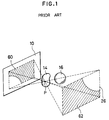
- the calculation of the phase distribution regarding a point P on the hologram forming surface 10 is set as follows.
- Embodiments of the invention may provide a hologram information forming method whereby a calculation amount when a hologram phase distribution is obtained is reduced.
- a hologram surface to express the phase distribution, a visual field in which a solid image that is reconstructed by the phase distribution expressed on the hologram surface can be seen, and a stereoscopic display limit are first set into a virtual space.
- a target to be stereoscopically displayed is subsequently displayed in the virtual space by a set of micro polygons.
- a plurality of slice planes which are parallel with the horizontal plane are set in the virtual space including the object.
- a line segment which crosses the polygon is obtained every slice plane. The line segment is divided or clipped as necessary.
- the line segment is further divided into a portion which can be always seen from the whole region of the visual field and a portion which is obstructed by another line segment and can be seen from only a part of the visual field, and those portions are extracted.
- Sampling points are set to the line segment.
- a 1-dimensional phase distribution on the hologram surface is calculated every sampling point.
- the one-dimensional hologram phase distributions calculated for the different sampling points are added every same slice plane.
- a 2-dimensional hidden line process of the computer graphics technique is modified and applied to the 3-dimensional structure data of the target held in a computer such as a CAD or the like, so that a 3-dimensional hidden line process which is necessary to set a calculating region of the hologram phase distribution can be simplified.
- a 1-dimensional hologram having a parallax in only the horizontal direction as a hologram to be formed the hidden line process and the calculations of the phase distribution can be simplified and an amount of calculations can be reduced.
- a flowchart of Fig. 2 shows a whole processing procedure of a stereoscopic display method including a hologram information forming method.
- a phase calculating process in step S1 a hologram phase distribution for stereoscopic display is calculated.
- the phase calculating process in this instance is executed as schematically shown in Fig. 3. That is, 3-dimensional information of the target objects 14 and 16 to be stereoscopically displayed is expressed in a virtual space prepared for phase calculation from a system such as a CAD system or the like in which 3-dimensional structure data has been held.
- a phase calculating region is determined and phase calculations in which a calculation amount was remarkably reduced are executed.
- a 1-dimensional hologram having a parallax in only the horizontal direction is calculated.
- the hologram surface 10 as a phase display surface is divided in the stripe-shaped regions each having a micro width in the vertical direction.
- the stripe-shaped region is divided into micro regions each having a micro width in the vertical direction of the target objects 14 and 16 in correspondence to the stripe-shaped regions.
- Sampling points are set in the divisional regions of the target objects 14 and 16 and phase contributions from the sampling points are product summed, thereby obtaining a 1-dimensional hologram 12.
- each of the target objects 14 and 16 is generally expressed as a polygon which is expressed by a set of micro triangular elements, a number of slice planes 18 which are parallel with the horizontal plane are set of micro intervals in the vertical directions, thereby slicing the target objects. Subsequently, line segments which are obtained by the intersection between each slice plane 18 and the triangular elements constructing the target objects 14 and 16 are extracted. Those line segments are regarded as target objects 14 and 16 and a phase distribution of the 1-dimensional hologram 12 is calculated. It is now assumed that the interval in the vertical direction of the slice planes 18 is equalized to an interval between the hologram planes 10 to express the 1-dimensional hologram 12. According to the invention as mentioned above, since the target objects 14 and 16 are cut by the slice planes 18 and are handled as line segments in the horizontal direction, so that the calculations of the phase distribution of the 1-dimensional hologram 12 can be further simplified.
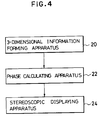
- Fig. 4 is a system constructional diagram corresponding to a procedure for stereoscopic display.
- the system is constructed by a 3-dimensional information forming apparatus 20, a phase calculating apparatus 22, and a stereoscopic display apparatus 24.
- a 3-dimensional information forming apparatus 20 for example, an apparatus such as a CAD system in which 3-dimensional structure data indicative of a target object has been held in a computer can be used.
- the phase calculating apparatus 22 an algorithm, which will be explained hereinlater, can be realized by a software or a hardware.
- the stereoscopic display apparatus 24 comprises: a liquid crystal display to express the 1-dimensional phase distribution obtained by the phase calculating apparatus 22; and a laser light source to irradiate a reference light for reproduction to the liquid crystal display.
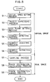
- a flowchart of Fig. 5 shows a fundamental processing procedure of the phase calculating process shown in step S1 in Fig. 2, namely, the hologram information forming method.
- Step S1 relates to a virtual space setting process.
- a rectangular hologram surface to express a phase distribution, a rectangular visual field which can observe a solid image that is reconstructed by the phase distribution expressed on the hologram surface, and a boundary surface indicative of a limit region in the stereoscopic display are set.
- Step S2 relates to an object expressing process.
- the target object to be stereoscopically displayed by using the CAD system or the like is expressed as a polygon constructed by a set of micro triangular area elements.
- Step S3 relates to slice plane setting process.
- a plurality of slice planes are set a micro intervals in the vertical direction so as to be parallel with the horizontal plane of a virtual space.
- a crossing state with the polygon as a target object expressed in step S2 is produced by the slice planes.
- Step S4 relates to a line segment detecting process. The line segments which are obtained by the intersection between the set slice planes and the triangular area elements constructing the target object expressed as a polygon are detected.
- Step S5 relates to a line segments adjusting process.
- a line segment adjusting process such that the line segments indicative of the target object detected by the setting of the slice planes, the overlapped portion of the line segment indicative of the target object detected by the setting of the slice planes is clipped in accordance with the relation with the boundary plane indicative of the stereoscopic display limit set in the virtual space or such that the line segment is divided in order to simplify the processes with respect to the intersection of the line segment.
- the line segment which cannot be seen from the whole visual plane because it is obstructed by the line segments existing on this side is divided into a portion that is always seen from the whole visual field and a portion that is obstructed by another line segment and can be seen from only a part of the visual field, and the line segment is extracted.
- the line segment at each slice plane is classified into the line segment which can by seen from the whole visual field and the line segment which is obstructed by another line segment and can be seen from only a part of the visual field.
- the processes in steps S1 to S6 mentioned above relate to the processes in the virtual space which has first been set.
- the virtual space here denotes a display apparatus to actually express a 1-dimensional phase distribution and a wavelength of reproduction light are not determined but a space is set with respect to the display and the wavelength of reproduction light which were virtually determined as a prerequisite.
- the processes in step S7 and subsequent steps they are executed in a structure of a display as a stereoscopic display apparatus to actually express a 1-dimensional phase distribution, specifically speaking, in a real space based on the pixel pitch interval and the wavelength of reference light which is actually used.
- sampling points for phase calculation are set on the line segment extracted every slice plane. Coordinate values and luminances are given with respect to the sampling points. As for the luminance of the sampling point, a value based on a hidden surface process in the computer graphics technique is used.
- a phase distribution calculating process in step S8 a phase distribution of a 1-dimensional hologram on the hologram surface is calculated every sampling point.
- 1-dimensional hologram phase distributions calculated for the different sampling points are added every same slice plane. A 1-dimensional phase distribution in the stripe region in the horizontal direction of the hologram surface is finally obtained.
- Fig. 6 visually shows a state of the virtual space setting process shown in step S1 in Fig. 5.
- the virtual hologram surface 10 and the virtual field 26 are set into the virtual space. It is now assumed that the hologram surface 10 has a structure such that micro pixels 25 which express the calculated phase values are 2-dimensionally arranged. Generally, about 1000 lp/mm is necessary as a resolution of the display that is needed for reconstruction of a hologram. Therefore, a size of pixel 25 is determined on the basis of such a resolution.
- a pitch interval of the pixels 25 provided on the virtual hologram surface 10 is set to P v .
- the hologram surface 10 has a size of a lateral width L 1 and a height of L 2 on the basis of the presumption of the virtual display.
- boundary surfaces 30 and 32 can be set. Namely, although a solid image by the hologram 10 can be seen by setting the visual point to the inside of the boundary surfaces 30 and 32, a solid image cannot be seen when the visual point is set to the outside of the boundary surfaces 30 and 32.
- the boundary surfaces 30 and 32 accordingly, determine a region in which a solid image can be observed.
- a polygon expressed in the virtual space while setting a visual point W 0 into an origin is coordinate converted into the coordinate system of the origin O at the center of the hologram surface 10. After that, the line segment is extracted.
- Fig. 8 shows an object expression for a virtual space and a setting state of slice planes.
- a target object (polygon) 34 formed by 3-dimensional structure data by a CAD system or the like is expressed in the virtual space.
- the target object 34 is expressed as a set of triangular planes and sides.
- the expression format of the polygon by the set of triangular elements 38 is constructed by a coupling list of the coordinate values of three vertexes of each plane element and the vertexes of the other plane elements.
- slice planes 18-1, 18-2, ---, 18-n are set in parallel with the horizontal plane.
- An interval among the slice planes 18-1 to 18-n is set to the pitch interval P v of the pixels 25 of the hologram surface 10.
- the slice planes 18-1 to 18-n can be also set at an interval which is equal to or larger than the pitch interval P v of the pixels 25.
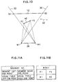
- Fig. 10 shows a state in which a line segment 40 which is seen from the whole visual field 26 with respect to a certain slice plane exists. End points of the visual field 26 are shown by W 1 and W 2 . End points of the hologram surface 10 are shown by S 1 and S 2 .
- the line segment 40 expressed by the coordinate values of the end points P 1 and P 2 exists in the region on the inside of the boundary surfaces 32 and 30.
- the line segment existing on the inside of the boundary surfaces 32 and 30 as shown in the line segment 40 is extracted as a target line segment of the phase calculation.
- a line segment 42 existing on the outside of the boundary surface 30 is deleted because it is not a target for calculation.
- Figs. 11A and 11B show a data format of the line segment 40 which can be seen from the whole region of the visual field 26 in Fig. 10. That is, Fig. 11A shows the content of the data format.
- the coordinate values of the left and right end points of the line segment are stored subsequent to the line segment number.
- the line segment has been divided at the right end point and the left end point, it is also possible to define this side as a start point and the depth side as an end point when they are seen in the depth direction. Subsequently, the coordinate values of the left end point and right end point of the visual field are stored.
- Fig. 12 shows a clipping process of a line segment.
- the line segment having the end points P 1 and P 2 since the end point P 1 exists on the outside of the boundary surface 32, a line segment 44 existing on the outside of a crossing point P 12 with the boundary surface 32 is deleted, thereby forming a new line segment 40 having the crossing point P 12 and the end point P 2 on the right side. Since the line segment 40 which was clipped as mentioned above can be seen from the whole region of the visual field 26, it has the same data format as that shown in Figs. 11A and 11B.
- Fig. 13 shows another example of the clipping process of a line segment.
- the line segment 42 having the end points P 1 and P 2 passes through both of the boundary surfaces 32 and 30 and exist. Therefore, crossing points P 3 and P 4 with the boundary surfaces 30 and 32 are obtained and are set to the end points of a new line segment and the line segment existing on the outside is deleted.
- Fig. 14 shows a line segment a part of which cannot be seen on the right side of the visual field 26.
- Another line segment 46 having end points P 3 and P 4 is located in front of the line segment 44 having the end points P 1 and P 2 .
- the line segment 44 is seen from the end point W 1 of the visual field 26, the whole region in a range from the end point P 1 to the end point P 2 can be seen.
- the line segment 44 is seen from the end point W 2 on the right side of the visual field 26, the right side from the point P 12 which passes through the end point P 3 of the line segment 46 and intersects the line segment 44 cannot be seen from the end point W 2 .
- the portion of the line segment 44 in a range from the end point P 1 to the crossing point P 12 can be seen from the whole region of the visual field 26, the portion in a range from the crossing point P 12 to the end point P 2 cannot be seen in the whole region of the visual field 26. Therefore, the portion to the crossing point P 12 is a limit range which can be seen in the whole visual field 26. Further, with respect to the right side, the visual field 26 in which the line segment can be seen is limited so as to be gradually narrowed toward the left side including the end point W 1 .
- the line segment 44 is divided into a line segment 48 having end points P 1 and P 12 which can be seen from the whole region of the visual field and a line segment 50 having end points P 12 and P 2 which cannot be seen in a part of the visual field, and they are extracted.
- the line segment 48 which can be seen from the whole region of the visual field has a data format as shown in Fig. 11.
- the line segment 50 a part of which cannot be seen on the right side of the visual field has a data format as shown in Figs. 15A and 15B.
- Fig. 15A shows the content of a data format of the line segment a part of which cannot be seen on the right side of the visual field.
- the line segment number, the left end point of the line segment, the right end point of the line segment, the left end point of the visual field, and the end point of the obstruction line segment are stored in the data format.
- the line segment number #002 the left end point P 12 of the line segment, the right end point P 2 of the line segment, the left end point W 1 of the visual field, and the end point P 3 of the obstruction line segment 46 are stored.
- 15A and 15B differs from the data format of the line segment which can be seen in the whole region of the visual field as shown in Figs. 11A and 11B with respect to a point that the end point of the obstruction line segment is stored in place of one of the end points of the visual field.
- Fig. 16 shows a line segment a part of which cannot be seen on the left side of the visual field in contrast with Fig. 14.
- a part of the line segment 44 having the end points P 1 and P 2 cannot be seen on the right side of the visual field 26 by the line segment 46 having the end points P 3 and P 4 existing in front of the line segment 44. That is, when the line segment is seen from the end point W 1 on the left side of the visual field 26, the portion to the crossing point P 12 with the eyesight line which passes through the end point P 4 of the another line segment 46 can be seen in the whole region of the visual field 26. However, the portion on the left side of the crossing point P 12 cannot be seen on the left side of the visual field 26 as it approaches the side of the end point P 1 side.
- the line segment 44 is divided into the line segment 48 having the end points P 12 and P 2 which can be seen in the whole region of the visual field 26 and the line segment 50 having the end points P 1 and P 12 a part of which cannot be seen on the left side of the visual field 26.
- the line segment 50 a part of which cannot be seen on the left side of the visual field 26 has a data format in which the line segment number #003, the right end point P 1 of the line segment, the left end point P 12 of the line segment, the end point P 4 of the obstruction line segment, and the left end point W 2 of the visual field are stored as shown in Figs. 17A and 17B.
- Fig. 18 shows a dividing process of an intersecting line segment.
- the line segment 44 having the end points P 1 and P 2 intersects the line segment 46 having the end points P 3 and P 4 at a crossing point P 5 as shown in the diagram
- the line segments are divided into four line segments by the crossing point P 5 . Since the divided line segment having the end points P 1 and P 5 and the divided line segment having the end points P 4 and P 5 can be seen from the whole region of the visual field 26, data according to the data format shown in Figs. 11A and 11B is produced.
- the line segment having the end points P 5 and P 3 and the line segment having the end points P 5 and P 2 are deleted because they are hidden by the two line segments on this side and cannot be seen at all from the visual field 26.
- the line segment data is sorted so as to be arranged in accordance with the order of the positions in the depth direction every slice plane.
- a calculating process of a 1-dimensional phase distribution of the hologram surface based on the line segments obtained every slice plane will now be described.
- the principle of a hologram will be first explained.
- One laser beam is divided into two beams and one of the laser beams is irradiated to an object, so that a laser beam (object light) is scattered by the object.
- a hologram is obtained by an interference of two line beams of the laser beams (object light) and another laser beam (reference light).
- the first term of the right side in the equation (2) shows that the wave front from the object was reproduced.
- the second term of the right side indicates a conjugate wave of the object light. From the above description of the principle, it will be understood that it is sufficient to calculate only the third term of the right side of the equation (1) in the calculation of the phase distribution of the hologram.
- Fig. 19 shows the principle of the calculation of a hologram.
- the reference light is constructed by a plane wave
- Fig. 20 shows a calculating region of a 1-dimensional phase distribution with respect to a line segment which can be seen from the whole region of a visual field. Since the line segment which can be seen in the whole region of the visual field is expressed by the data format shown in Figs. 11A and 11B, the end points P 1 and P 2 of the line segment and the end points W 1 and W 2 of the visual field 26 can be set into the virtual space for the hologram surface 10 as shown in the diagram. First, in the invention, a sampling points SP are set onto the line segment having the end points P 1 and P 2 .
- a division length of the line segment to decide the sampling points is set to an enough small value in order to allow a continuous state of a plurality of line segments to be seen as one line.
- a division length of the line segment to set the sampling points is visually set to a value of about 50 ⁇ m.
- sampling points SP 1 , SP 2 , -- are set every pitch interval P v by using the pitch interval P v of the pixels of the hologram surface 10 provided in the virtual space.
- a calculating region of the phase distribution on the hologram surface 10 at the end point P 1 is set to a calculating region 52-1 which is given by the interval of the crossing points on the hologram surface 10 of the eyesight lines from the end points W 1 and W 2 of the visual field 26.
- a calculating region is also similarly set to a region 52-2 between the crossing points at which the eyesight lines from the end points W 1 and W 2 on both sides of the visual field 26 intersect the hologram surface 10.
- calculating regions are obtained with respect to the other remaining sampling points and the end point P 2 on the right side.
- a calculating region 52-6 is determined with respect to the end point P 2 .
- phase calculation at each sampling point shown in Fig. 20 since the phase distribution is calculated on the basis of the luminance at each sampling point including the end points P 1 and P 2 , it is necessary to previously obtain the luminances prior to the phase calculation.
- Such a calculation of the luminance at the sampling point can be realized by applying various kinds of shading models in the computer graphics.
- geometrical normal lines of the plane to display the end points P 1 and P 2 of the line segment are previously obtained as shown by broken lines as shown in Fig. 21.
- the normal lines now assume eyesight line vectors V 1 and V 2 .
- an eyesight line vector V i is obtained by a linear interpolation from the eyesight line vectors V 1 and V 2 at both end points P 1 and P 2 .
- the normal lines of the end points P 1 and P 2 have different directions because they are obtained by the average with the normal lines of the adjacent plane.
- a diffusion coefficient, a reflection coefficient, light source information, and the like are provided as various kinds of attribute information in a manner similar to the case of the display in the computer graphics.
- the calculation of the luminance is not limited to the smooth shading model of the computer graphics but a proper hidden plane processing technique can be applied.
- Fig. 22 shows the phase calculation of a line segment which cannot be seen in a part of the visual field.
- the end points P 12 and P 2 of the line segment, the left end point W 1 of the visual field, and the end point P 3 of the obstruction line segment are set to the hologram surface 10 on the basis of the line segment data in Fig. 15B.
- the line segment having the end points P 12 and P 2 is divided by, for example, a division length of the pixel pitch interval P v of the virtual hologram surface 10 and the sampling point SP 1 is provided.
- a region of the phase calculation on the hologram surface 10 based on the light from the point P 12 is set to a region 54-1 between the left end point W 1 of the visual field 26 and the crossing point on the hologram surface 10 of the eyesight line which starts from the end point P 3 of the obstruction line and passes through the point P 12 .
- calculating regions 54-2 and 54-3 are similarly obtained.
- the luminance at the points P 12 , SP 1 , and P 2 are obtained in a manner similar to the case of Fig. 21.
- a phase distribution is calculated every pixel included in the calculating regions 54-1 to 54-3 in accordance with the equations (3) and (4).
- phase calculations shown in Figs. 20 to 22 have been performed with respect to the virtual spaces shown in Figs. 6 to 7 as examples, in the actual processes, a phase distribution in a real space in which the display to actually express the phase distribution at the stage of the phase calculation and the wavelength of the reproduction light were specified is calculated.
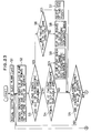
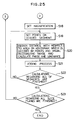
- Figs. 23 to 25 show flowcharts for realizing the processes in step S3 and subsequent steps to form hologram information according to the invention shown in Fig. 5 by a software.
- a slice plane is initialized in step S1.
- step S2 crossing points of the set slice plane and the polygon expressed as a target object are obtained and set to two end points of the line segment.
- step S3 a check is made to see if the two end points of the line segment lie within a region in which the stereoscopic display can be performed or not. If NO, a check is made in step S4 to see if one of the two end points is out of the stereoscopic displayable region or not.
- step S5 the processing routine advances to step S5 and a check is made to see if the calculations to extract the line segments have been finished with respect to all of the plane elements of the polygon or not.
- step S6 the processing routine advances to step S6 and a check is made to see if the two end points exist in the same direction on either the right side or the left side when they are seen from the visual field or not.
- the two end points of the line segment exist in the same direction, namely, on the right side or the left side of the stereoscopic displayable region, specifically speaking, in the case as shown by the line segment 42 in Fig.
- step S7 follows and the data of two end points is deleted.
- step S8 follows and both of the two end points are clipped into the stereoscopic displayable region.
- step S11 A check is made in step S11 to see if the line segment between the two end points has a crossing point or not. If YES, step S13 follows and the line segment is divided at the crossing point and line segments are added as shown in Fig. 18. The above processes are repeated until the judgment of the crossing point is finished with respect to all of the line segments in step S12. The processing routine advances to step S14 and the line segments after completion of the process of the crossing point was finished are rearranged. In this rearrangement, the line segments on the same slice plane are sequentially arranged in accordance with the ascending order in the direction of the Z axis, namely, in the depth direction (in accordance with the order from the small distance in the depth direction).
- step S15 One of the two end points which is close to the visual field with respect to each line segment is set to a starting point and the other point which is far from the visual field is set to an end point (terminal point).
- step S15 the initialization of the line segments is again executed in step S15.
- the line segments are extracted in step S16.
- the line segment which is hidden in a part of the visual field is divided into the following three portions: I) a portion which can be perfectly seen from the visual field; II) a portion which can be seen in dependence on the angle; and III) a portion which cannot be seen at all. The portion which cannot be seen is eliminated.
- step S16 is repeated until the end of calculations about all of the line segments in step S17.
- magnification is set in order to convert from the processes in the virtual space so far into the processes in the real space in which the display to actually display the phase distribution and the wavelength of reference light have been determined.
- the magnification since the pixel pitch interval P v of the hologram surface in the virtual space and the pixel pitch interval P r in the real space have been predetermined, the magnification (P r /P v ) is set, the conversion of the wavelength and the number of waves into the real space according to the equations (5) and (6) is executed, and the phase calculations according to the equations (3) and (4) are executed by using the wavelength ⁇ v and the number of waves (k v ).
- step S18 After the magnification was set in step S18, sampling points are set onto the line segment every line segment at a predetermined division length, for example, at the pixel pitch interval P v on the hologram surface in the virtual space.
- step S20 the distance, namely, calculating region is obtained with respect to the region on the hologram surface which is determined by the sampling points on the line segment and the observing range of the visual field, the luminance at the sampling point is further obtained, and a phase distribution is finally calculated every pixel of the calculating region.
- step S21 the calculated phase distributions are added because the processes relate to the same slice plane. The processes in steps S19 to S21 are repeated until the calculations are finished with respect to all of the line segments in step S22.
- step S23 follows and a check is made to see if the calculations about all of the slice plane are finished or not. If NO, the processing routine is returned to step S2 in Fig. 23 and the processes regarding the next slice plane are executed. After completion of the calculations about all of the slice planes in step S23 in Fig. 25, a series of hologram information forming processed are finished.
- the 1-dimensional phase distribution of each slice surface calculated as mentioned above is held into, for example, a memory of the phase calculating apparatus 22 shown in Fig. 4 and is read out when a stereoscopic display is executed by the stereoscopic display apparatus 24.
- the corresponding phase distribution is expressed every pixel of the liquid crystal device, the reference light is irradiated to the phase distribution from a laser light source or the like, and the reference light is converted into the wave front on the basis of the phase distribution expressed, and a solid image based on the 1-dimensional phase distribution formed is displayed.
- a liquid crystal display using a nematic liquid crystal can be used as a device which is used in the stereoscopic display.
- Each liquid crystal element changes the phase of reference light in a range from 0 to 2 ⁇ by a phase distribution signal and executes the wave front conversion to display a solid image.
- an object as a display target is expressed by a polygon constructed by a set of triangular plane elements and the line segment due to the intersection of the polygon plane elements is obtained every slice plane set in the virtual space for the phase calculation so as to be parallel with the horizontal plane. Due to this, by obtaining the 1-dimensional phase distribution in which the sampling points were set onto the line segment at regular intervals, an amount of calculations of the phase distribution of the hologram which needed an extremely large amount of calculations hitherto can be remarkably reduced.
- the line segments which express the target object are extracted in the virtual space in which the hologram surface, visual field, and boundary surfaces were set. Prior to the phase calculation, the processes are converted from the virtual space into the real space in which the actual display device or the wavelength of reference light were considered, thereby obtaining the 1-dimensional phase distribution.
- the line segment information of the target serving as a base of the phase calculation can be unconditionally obtained without being limited to the device for stereoscopic display.
- the phase calculation adapted to the actual apparatus can be easily executed. Further, since the technique of the hidden plane process in the computer graphics is used in the luminance calculation of the line segment, a solid image having a real stereoscopic feeling can be displayed.
Landscapes
- Physics & Mathematics (AREA)
- General Physics & Mathematics (AREA)
- Holo Graphy (AREA)
Claims (17)
- Ein Hologramminformationsbildungsverfahren mit:einem Schritt zum Festlegen eines virtuellen Raumes, der in einem virtuellen Raum das Definieren einer Hologrammoberfläche umfaßt, bei der eine Phasenverteilung zu berechnen ist, eines Sehfeldes, von dem aus das Bild des Objektes sichtbar ist, das durch die Phasenverteilung auf der genannten Hologrammoberfläche zu rekonstruieren ist, und stereoskopischer Anzeigegrenzen;einem Objektdarstellungsschritt, der das Definieren des Objektes, das in dem genannten virtuellen Raum stereoskopisch anzuzeigen ist, durch einen Satz von Mikropolygonen umfaßt;einem Schritt zum Festlegen von Schnittebenen, der das Definieren von einer Vielzahl von parallelen Ebenen in dem genannten virtuellen Raum umfaßt, die das genannte Objekt kreuzen;einem Liniensegmentberechnungsschritt, der das Berechnen der Liniensegmente umfaßt, die aus dem Überschneiden der genannten Polygone mit jeder der genannten Schnittebenen resultieren;einem Liniensegmenteinstellschritt, der das Abschneiden der Abschnitte der genannten Liniensegmente außerhalb der stereoskopischen Anzeigegrenzen und das Teilen der Schnittliniensegmente an ihren Kreuzungspunkten umfaßt;einem Liniensegmentextraktionsschritt zum Teilen der verbleibenden Liniensegmente in Abschnitte, die von der gesamten Zone des genannten Sehfeldes aus gesehen werden können, und in Abschnitte, die durch andere Liniensegmente versperrt sind und somit nur von einem Teil des Sehfeldes aus gesehen werden können, wodurch die sichtbaren Liniensegmente extrahiert werden;einem Abtastschritt zum Festlegen von Abtastpunkten auf den extrahierten sichtbaren Liniensegmenten;einem Phasenverteilungsberechnungsschritt für jede Schnittebene, zum Berechnen einer eindimensionalen Hologrammphasenverteilung auf der genannten Hologrammoberfläche für jeden der genannten Abtastpunkte in jener Schnittebene; undeinem Phasenverteilungsaddierschritt für jede Schnittebene, zum Addieren der genannten eindimensionalen Hologrammphasenverteilungen, die für alle verschiedenen Abtastpunkte in jener Schnittebene berechnet wurden.
- Ein Verfahren nach Anspruch 1, wobei bei dem genannten Schritt zum Festlegen des virtuellen Raumes eine diagonale Ebene, die durch Verbinden der gegenüberliegenden Seiten der rechteckigen Hologrammoberfläche und entsprechender gegenüberliegender Seiten des Sehfeldes konstruiert wird, als Grenzoberfläche festgelegt wird, die die genannten stereoskopischen Anzeigegrenzen bezeichnet.
- Ein Verfahren nach Anspruch 1 oder 2, wobei bei dem genannten Schritt zum Festlegen des virtuellen Raumes ein Ursprung mit 3-dimensionalen Koordinaten an der zentralen Position der Hologrammoberfläche festgelegt wird und Positionskoordinaten im virtuellen Raum unter Verwendung des genannten Ursprungs als Referenz dargestellt werden.
- Ein Verfahren nach Anspruch 1, 2 oder 3, wobei die genannten Polygone bei dem genannten Objektdarstellungsschritt Dreiecksebenenelemente sind.
- Ein Verfahren nach irgendeinem der vorhergehenden Ansprüche, wobei bei dem genannten Schritt zum Festlegen von Schnittebenen eine Vielzahl von Ebenen in regelmäßigen Intervallen festgelegt wird.
- Ein Verfahren nach irgendeinem der vorhergehenden Ansprüche, wobei bei dem genannten Liniensegmenteinstellschritt der Abschnitt außerhalb der Grenzoberfläche der genannten stereoskopischen Anzeigegrenzen bezüglich des Liniensegmentes in der Schnittebene abgeschnitten wird, wodurch das Liniensegment auf die Anzeigegrenzen begrenzt wird.
- Ein Verfahren nach irgendeinem der vorhergehenden Ansprüche, wobei bei dem genannten Liniensegmenteinstellschritt zwei oder mehr Schnittliniensegmente an ihren Kreuzungspunkten geteilt werden.
- Ein Verfahren nach irgendeinem der vorhergehenden Ansprüche, wobei bei dem genannten Liniensegmentextraktionsschritt eine Gruppe von Endpunkten auf beiden Seiten des Liniensegmentes und zwei Punkte, die die Sichtbarkeit des Liniensegmentes begrenzen, Liniensegmentinformationen bilden.
- Ein Verfahren nach Anspruch 8, wobei bei dem genannten Liniensegmentextraktionsschritt hinsichtlich des Liniensegmentes, das von der gesamten Zone des Sehfeldes aus gesehen werden kann, eine Gruppe von Endpunkten auf beiden Seiten des Liniensegmentes und Endpunkte auf beiden Seiten des Sehfeldes Liniensegmentinformationen bilden.
- Ein Verfahren nach Anspruch 8, wobei bei dem genannten Liniensegmentextraktionsschritt hinsichtlich des Liniensegmentes, das von einem Teil des Sehfeldes aus gesehen werden kann, Endpunkte eines anderen Liniensegmentes, das die Beobachtung begrenzt, Liniensegmentinformationen bilden.
- Ein Verfahren nach irgendeinem der vorhergehenden Ansprüche, wobei bei dem genannten Abtastschritt Abtastpunkte auf den extrahierten Liniensegmenten in regelmäßigen Intervallen festgelegt werden.
- Ein Verfahren nach irgendeinem der vorhergehenden Ansprüche, bei dem das Festlegungsintervall der Abtastpunkte auf der Basis einer Auflösung des menschlichen Auges festgelegt wird, bei der ein Array der genannten Abtastpunkte als kontinuierliche Linie gesehen werden kann, wenn es von einer Position aus gesehen wird, die von dem genannten Array der Abtastpunkte durch einen vorbestimmten Abstand entfernt ist.
- Ein Verfahren nach Anspruch 12, bei dem der Abstand zu dem Sehpunkt, der verwendet wird, um das Intervall der Abtastpunkte zu bestimmen, derselbe wie der Abstand zwischen der Hologrammoberfläche, die in dem virtuellen Raum festgelegt ist, und dem Sehfeld ist.
- Ein Verfahren nach irgendeinem der vorhergehenden Ansprüche, wobei bei dem genannten Phasenverteilungsberechnungsschritt eine Vergrößerung für die Informationen der Liniensegmente festgelegt wird, die im virtuellen Raum erhalten wurden, um die Anzeigebedingungen an den realen Raum anzupassen, in dem die Wiedergabe der stereoskopischen Anzeige erfolgt.
- Ein Verfahren nach Anspruch 14, bei dem die Festlegung der Vergrößerung bei dem Phasenverteilungsberechnungsschritt auf der Basis des Verhältnisses des Pixelabstandsintervalls auf der Hologrammoberfläche, die in dem virtuellen Raum festgelegt ist, und des Pixelabstandsintervalls der Anzeige erfolgt.
- Ein Verfahren nach irgendeinem der vorhergehenden Ansprüche, mit:einem Phasenverteilungsaufzeichnungsschritt zum Aufzeichnen der berechneten eindimensionalen Phasenverteilung in einem Medium; undeinem stereoskopischen Anzeigeschritt zum Einstrahlen von Referenzlicht auf die Phasenverteilung in dem genannten Medium und zum Konvertieren des Referenzlichtes in eine Wellenfront, die das Bild des Objektes rekonstruiert.
- Ein Verfahren nach irgendeinem der vorhergehenden Ansprüche, bei dem die eindimensionalen Hologrammphasenverteilungen für jede der Schnittebenen berechnet werden und Seite an Seite angeordnet werden, wodurch die Phasenverteilung des gesamten Hologramms gebildet wird.
Applications Claiming Priority (2)
| Application Number | Priority Date | Filing Date | Title |
|---|---|---|---|
| JP275838/92 | 1992-10-14 | ||
| JP4275838A JP2999637B2 (ja) | 1992-10-14 | 1992-10-14 | ホログラム情報作成方法 |
Publications (2)
| Publication Number | Publication Date |
|---|---|
| EP0593300A1 EP0593300A1 (de) | 1994-04-20 |
| EP0593300B1 true EP0593300B1 (de) | 1997-01-02 |
Family
ID=17561139
Family Applications (1)
| Application Number | Title | Priority Date | Filing Date |
|---|---|---|---|
| EP93308211A Expired - Lifetime EP0593300B1 (de) | 1992-10-14 | 1993-10-14 | Verfahren zum Erzeugen von holographischer Information |
Country Status (5)
| Country | Link |
|---|---|
| US (1) | US5400155A (de) |
| EP (1) | EP0593300B1 (de) |
| JP (1) | JP2999637B2 (de) |
| CA (1) | CA2107945C (de) |
| DE (1) | DE69307088T2 (de) |
Families Citing this family (28)
| Publication number | Priority date | Publication date | Assignee | Title |
|---|---|---|---|---|
| JPH0635392A (ja) * | 1992-07-20 | 1994-02-10 | Fujitsu Ltd | 立体表示装置 |
| JP3238755B2 (ja) * | 1992-08-21 | 2001-12-17 | 富士通株式会社 | ホログラムの作成および立体表示方法並びに立体表示装置 |
| JP3338479B2 (ja) * | 1992-09-18 | 2002-10-28 | 富士通株式会社 | ホログラムの作成および立体表示方法並びに立体表示装置 |
| JPH07253749A (ja) * | 1994-03-15 | 1995-10-03 | Fujitsu Ltd | 立体表示装置 |
| US5864384A (en) * | 1996-07-31 | 1999-01-26 | Mcclure; Richard J. | Visual field testing method and apparatus using virtual reality |
| US5910834A (en) * | 1996-07-31 | 1999-06-08 | Virtual-Eye.Com, Inc. | Color on color visual field testing method and apparatus |
| US6277037B1 (en) | 1997-10-03 | 2001-08-21 | Performance Dynamics Llc | Golf ball with water immersion indicator |
| US6608911B2 (en) * | 2000-12-21 | 2003-08-19 | Digimarc Corporation | Digitally watermaking holograms for use with smart cards |
| EP1008919A1 (de) * | 1998-12-09 | 2000-06-14 | Communauté Européenne (CE) | Computergestütztes Verfahren und Vorrichtung zur Wiedergabe von dreidimensionalen Bildern |
| US6195184B1 (en) | 1999-06-19 | 2001-02-27 | The United States Of America As Represented By The Administrator Of The National Aeronautics And Space Administration | High-resolution large-field-of-view three-dimensional hologram display system and method thereof |
| CH695282A5 (de) * | 1999-10-15 | 2006-02-28 | Franz R Klingenberg | Abbildung eines Ausschnittes der Oberflaeche eines Himmelskoerpers, Verfahren zur Herstellung der Abbildung und Verwendung der Abbildung. |
| WO2002039387A1 (en) * | 2000-11-07 | 2002-05-16 | Holographic Imaging Llc | Improved three dimensional display |
| CA2364601A1 (en) * | 2001-12-03 | 2003-06-03 | Utar Scientific Inc. | Computer-assisted hologram forming method and apparatus |
| JP3895166B2 (ja) * | 2001-12-17 | 2007-03-22 | 大日本印刷株式会社 | 計算機ホログラムの作成方法 |
| JP4412576B2 (ja) * | 2002-10-16 | 2010-02-10 | 大日本印刷株式会社 | 立体マイクロパターン表示体 |
| JP4390574B2 (ja) * | 2003-03-31 | 2009-12-24 | 富士通株式会社 | 複数のポリゴンから構成される3次元モデルを2次元平面に投影する際の陰線を消去する陰線処理方法 |
| US7580170B2 (en) * | 2003-11-04 | 2009-08-25 | Dai Nippon Printing Co., Ltd. | Fabrication method for a computer-generated hologram or a holographic stereogram in which a three-dimensional object having visualized cross-sectional surfaces is recorded and computer-generated hologram/holographic |
| DE102004063838A1 (de) * | 2004-12-23 | 2006-07-06 | Seereal Technologies Gmbh | Verfahren und Einrichtung zum Berechnen computer generierter Videohologramme |
| KR100664872B1 (ko) * | 2005-04-11 | 2007-01-03 | 김영철 | 1차원 홀로그램을 이용한 영상 표시장치 |
| DE102007013431B4 (de) * | 2007-03-15 | 2018-07-05 | Seereal Technologies S.A. | Verfahren und Einrichtung zum Rekonstruieren einer dreidimensionalen Szene mit korrigierter Sichtbarkeit |
| US9581965B2 (en) | 2007-05-16 | 2017-02-28 | Seereal Technologies S.A. | Analytic method for computing video holograms in real time |
| DE102007023739B4 (de) * | 2007-05-16 | 2018-01-04 | Seereal Technologies S.A. | Verfahren zum Rendern und Generieren von Farbvideohologrammen in Echtzeit und holographische Wiedergabeeinrichtung |
| DE102007023785B4 (de) * | 2007-05-16 | 2014-06-18 | Seereal Technologies S.A. | Analytisches Verfahren zu Berechnung von Videohologrammen in Echtzeit und holographische Wiedergabeeinrichtung |
| JP5246864B2 (ja) * | 2008-12-11 | 2013-07-24 | 独立行政法人情報通信研究機構 | ホログラム生成装置、ホログラム生成方法およびホログラム生成プログラム |
| US20100174510A1 (en) * | 2009-01-05 | 2010-07-08 | Greco Franklin L | Method and System for Generating and Providing Seating Information for an Assembly Facility with Obstructions |
| KR102262214B1 (ko) * | 2014-09-23 | 2021-06-08 | 삼성전자주식회사 | 홀로그래픽 3차원 영상 표시 장치 및 방법 |
| WO2024004739A1 (ja) * | 2022-06-28 | 2024-01-04 | ソニーグループ株式会社 | 情報処理装置、情報処理方法、および、コンピュータ読み取り可能な非一時的記憶媒体 |
| WO2024095753A1 (ja) * | 2022-11-02 | 2024-05-10 | ソニーグループ株式会社 | 表示処理装置、および表示処理方法、並びに記憶媒体 |
Family Cites Families (7)
| Publication number | Priority date | Publication date | Assignee | Title |
|---|---|---|---|---|
| US3816726A (en) * | 1972-10-16 | 1974-06-11 | Evans & Sutherland Computer Co | Computer graphics clipping system for polygons |
| US3889107A (en) * | 1972-10-16 | 1975-06-10 | Evans & Sutherland Computer Co | System of polygon sorting by dissection |
| US4669812A (en) * | 1983-09-12 | 1987-06-02 | Hoebing John L | Method and apparatus for 3-D image synthesis |
| US4778262A (en) * | 1986-10-14 | 1988-10-18 | American Bank Note Holographics, Inc. | Computer aided holography and holographic computer graphics |
| US5088054A (en) * | 1988-05-09 | 1992-02-11 | Paris Ii Earl A | Computer graphics hidden surface removal system |
| US5138471A (en) * | 1990-07-20 | 1992-08-11 | Mcgrew Stephen P | Holocomposer |
| US5237433A (en) * | 1992-01-03 | 1993-08-17 | Haines Kenneth A | Methods of hologram construction using computer-processed objects |
-
1992
- 1992-10-14 JP JP4275838A patent/JP2999637B2/ja not_active Expired - Lifetime
-
1993
- 1993-10-07 CA CA002107945A patent/CA2107945C/en not_active Expired - Fee Related
- 1993-10-12 US US08/134,825 patent/US5400155A/en not_active Expired - Lifetime
- 1993-10-14 DE DE69307088T patent/DE69307088T2/de not_active Expired - Lifetime
- 1993-10-14 EP EP93308211A patent/EP0593300B1/de not_active Expired - Lifetime
Also Published As
| Publication number | Publication date |
|---|---|
| CA2107945A1 (en) | 1994-04-15 |
| JPH06130881A (ja) | 1994-05-13 |
| EP0593300A1 (de) | 1994-04-20 |
| DE69307088D1 (de) | 1997-02-13 |
| DE69307088T2 (de) | 1997-04-17 |
| CA2107945C (en) | 1997-07-01 |
| US5400155A (en) | 1995-03-21 |
| JP2999637B2 (ja) | 2000-01-17 |
Similar Documents
| Publication | Publication Date | Title |
|---|---|---|
| EP0593300B1 (de) | Verfahren zum Erzeugen von holographischer Information | |
| Herman et al. | Three-dimensional display of human organs from computed tomograms | |
| CA2104904C (en) | Stereoscopic display method and apparatus | |
| US6437782B1 (en) | Method for rendering shadows with blended transparency without producing visual artifacts in real time applications | |
| JP4204670B2 (ja) | ボリュームデータ表現システム | |
| US20020109684A1 (en) | Method and apparatus for visualization of 3D voxel data using lit opacity volumes with shading | |
| CN102332179B (zh) | 三维模型数据化简、渐进传输方法及装置 | |
| Kaufman et al. | Intermixing surface and volume rendering | |
| US20060197780A1 (en) | User control of 3d volume plane crop | |
| CN111009033B (zh) | 一种基于OpenGL的病灶区域的可视化方法和系统 | |
| JPH02899A (ja) | グラフ表示装置と物体の3次元像を発生する方法 | |
| CN207541416U (zh) | 一种能够表示再现像遮挡关系的计算全息三维显示装置 | |
| US6600487B1 (en) | Method and apparatus for representing, manipulating and rendering solid shapes using volumetric primitives | |
| US6603475B1 (en) | Method for generating stereographic image using Z-buffer | |
| Kovač et al. | Visualization of LIDAR datasets using point-based rendering technique | |
| US20040179010A1 (en) | Apparatus and method for semi-automatic classification of volume data | |
| Bair et al. | Grid with a view: Optimal texturing for perception of layered surface shape | |
| Interrante et al. | Investigating the effect of texture orientation on the perception of 3D shape | |
| JP3586871B2 (ja) | 三次元ct画像の表示方法 | |
| EP0373854B1 (de) | Vorrichtung und Verfahren zur Ermittlung von inneren Strukturen innerhalb eines festen Objekts | |
| Wood | Visualization and modeling of 3-D structures (medical imaging) | |
| US5821942A (en) | Ray tracing through an ordered array | |
| Leith | Computer visualization of volume data in electron tomography | |
| KR102083558B1 (ko) | 복셀리곤을 이용한 3차원 객체 모델링 방법 및 프로그램 | |
| JPH09259298A (ja) | 疑似三次元画像構成方法 |
Legal Events
| Date | Code | Title | Description |
|---|---|---|---|
| PUAI | Public reference made under article 153(3) epc to a published international application that has entered the european phase |
Free format text: ORIGINAL CODE: 0009012 |
|
| AK | Designated contracting states |
Kind code of ref document: A1 Designated state(s): DE FR GB |
|
| 17P | Request for examination filed |
Effective date: 19940531 |
|
| GRAG | Despatch of communication of intention to grant |
Free format text: ORIGINAL CODE: EPIDOS AGRA |
|
| 17Q | First examination report despatched |
Effective date: 19960111 |
|
| GRAH | Despatch of communication of intention to grant a patent |
Free format text: ORIGINAL CODE: EPIDOS IGRA |
|
| GRAH | Despatch of communication of intention to grant a patent |
Free format text: ORIGINAL CODE: EPIDOS IGRA |
|
| GRAH | Despatch of communication of intention to grant a patent |
Free format text: ORIGINAL CODE: EPIDOS IGRA |
|
| GRAA | (expected) grant |
Free format text: ORIGINAL CODE: 0009210 |
|
| AK | Designated contracting states |
Kind code of ref document: B1 Designated state(s): DE FR GB |
|
| REF | Corresponds to: |
Ref document number: 69307088 Country of ref document: DE Date of ref document: 19970213 |
|
| ET | Fr: translation filed | ||
| PLBE | No opposition filed within time limit |
Free format text: ORIGINAL CODE: 0009261 |
|
| 26N | No opposition filed | ||
| REG | Reference to a national code |
Ref country code: GB Ref legal event code: IF02 |
|
| PGFP | Annual fee paid to national office [announced via postgrant information from national office to epo] |
Ref country code: DE Payment date: 20091008 Year of fee payment: 17 |
|
| PGFP | Annual fee paid to national office [announced via postgrant information from national office to epo] |
Ref country code: GB Payment date: 20091014 Year of fee payment: 17 Ref country code: FR Payment date: 20091029 Year of fee payment: 17 |
|
| GBPC | Gb: european patent ceased through non-payment of renewal fee |
Effective date: 20101014 |
|
| PG25 | Lapsed in a contracting state [announced via postgrant information from national office to epo] |
Ref country code: FR Free format text: LAPSE BECAUSE OF NON-PAYMENT OF DUE FEES Effective date: 20101102 |
|
| REG | Reference to a national code |
Ref country code: FR Ref legal event code: ST Effective date: 20110630 |
|
| REG | Reference to a national code |
Ref country code: DE Ref legal event code: R119 Ref document number: 69307088 Country of ref document: DE Effective date: 20110502 |
|
| PG25 | Lapsed in a contracting state [announced via postgrant information from national office to epo] |
Ref country code: GB Free format text: LAPSE BECAUSE OF NON-PAYMENT OF DUE FEES Effective date: 20101014 |
|
| PG25 | Lapsed in a contracting state [announced via postgrant information from national office to epo] |
Ref country code: DE Free format text: LAPSE BECAUSE OF NON-PAYMENT OF DUE FEES Effective date: 20110502 |