EP0593321A1 - Vorrichtung zur Osteosynthese von Rückenwirbeln - Google Patents
Vorrichtung zur Osteosynthese von Rückenwirbeln Download PDFInfo
- Publication number
- EP0593321A1 EP0593321A1 EP93402234A EP93402234A EP0593321A1 EP 0593321 A1 EP0593321 A1 EP 0593321A1 EP 93402234 A EP93402234 A EP 93402234A EP 93402234 A EP93402234 A EP 93402234A EP 0593321 A1 EP0593321 A1 EP 0593321A1
- Authority
- EP
- European Patent Office
- Prior art keywords
- plate
- screw
- thread
- spinal osteosynthesis
- pedicle
- Prior art date
- Legal status (The legal status is an assumption and is not a legal conclusion. Google has not performed a legal analysis and makes no representation as to the accuracy of the status listed.)
- Granted
Links
- 230000009467 reduction Effects 0.000 claims abstract description 28
- BASFCYQUMIYNBI-UHFFFAOYSA-N platinum Chemical compound [Pt] BASFCYQUMIYNBI-UHFFFAOYSA-N 0.000 claims description 51
- 230000009471 action Effects 0.000 claims description 37
- 229910052697 platinum Inorganic materials 0.000 claims description 15
- 230000003247 decreasing effect Effects 0.000 claims description 2
- 230000000903 blocking effect Effects 0.000 abstract description 6
- 239000000463 material Substances 0.000 description 23
- 210000000988 bone and bone Anatomy 0.000 description 15
- 230000006835 compression Effects 0.000 description 7
- 238000007906 compression Methods 0.000 description 7
- 206010039722 scoliosis Diseases 0.000 description 6
- 230000008602 contraction Effects 0.000 description 4
- 238000004519 manufacturing process Methods 0.000 description 4
- 238000000034 method Methods 0.000 description 4
- 230000001575 pathological effect Effects 0.000 description 4
- 208000007623 Lordosis Diseases 0.000 description 3
- 230000000694 effects Effects 0.000 description 3
- 208000014674 injury Diseases 0.000 description 3
- 206010017076 Fracture Diseases 0.000 description 2
- PEDCQBHIVMGVHV-UHFFFAOYSA-N Glycerine Chemical compound OCC(O)CO PEDCQBHIVMGVHV-UHFFFAOYSA-N 0.000 description 2
- 206010023509 Kyphosis Diseases 0.000 description 2
- 230000006978 adaptation Effects 0.000 description 2
- 229910045601 alloy Inorganic materials 0.000 description 2
- 239000000956 alloy Substances 0.000 description 2
- 230000008901 benefit Effects 0.000 description 2
- 230000003412 degenerative effect Effects 0.000 description 2
- 239000011159 matrix material Substances 0.000 description 2
- 230000007170 pathology Effects 0.000 description 2
- 235000012830 plain croissants Nutrition 0.000 description 2
- 230000002787 reinforcement Effects 0.000 description 2
- 208000020431 spinal cord injury Diseases 0.000 description 2
- 238000011477 surgical intervention Methods 0.000 description 2
- 230000008733 trauma Effects 0.000 description 2
- 206010002091 Anaesthesia Diseases 0.000 description 1
- 206010010356 Congenital anomaly Diseases 0.000 description 1
- 208000034656 Contusions Diseases 0.000 description 1
- 206010015082 Epiphysitis Diseases 0.000 description 1
- 208000021642 Muscular disease Diseases 0.000 description 1
- 201000009623 Myopathy Diseases 0.000 description 1
- 206010028980 Neoplasm Diseases 0.000 description 1
- 201000009859 Osteochondrosis Diseases 0.000 description 1
- 208000001132 Osteoporosis Diseases 0.000 description 1
- 208000000474 Poliomyelitis Diseases 0.000 description 1
- 206010039203 Road traffic accident Diseases 0.000 description 1
- 208000007103 Spondylolisthesis Diseases 0.000 description 1
- 229910001069 Ti alloy Inorganic materials 0.000 description 1
- RTAQQCXQSZGOHL-UHFFFAOYSA-N Titanium Chemical compound [Ti] RTAQQCXQSZGOHL-UHFFFAOYSA-N 0.000 description 1
- 241000722921 Tulipa gesneriana Species 0.000 description 1
- 208000027418 Wounds and injury Diseases 0.000 description 1
- 230000001944 accentuation Effects 0.000 description 1
- 230000001154 acute effect Effects 0.000 description 1
- XAGFODPZIPBFFR-UHFFFAOYSA-N aluminium Chemical compound [Al] XAGFODPZIPBFFR-UHFFFAOYSA-N 0.000 description 1
- 229910052782 aluminium Inorganic materials 0.000 description 1
- 230000037005 anaesthesia Effects 0.000 description 1
- 210000003484 anatomy Anatomy 0.000 description 1
- 238000004873 anchoring Methods 0.000 description 1
- 210000001264 anterior cruciate ligament Anatomy 0.000 description 1
- 239000000560 biocompatible material Substances 0.000 description 1
- 201000011510 cancer Diseases 0.000 description 1
- 230000008859 change Effects 0.000 description 1
- 238000004140 cleaning Methods 0.000 description 1
- 230000009519 contusion Effects 0.000 description 1
- 230000006378 damage Effects 0.000 description 1
- 229910003460 diamond Inorganic materials 0.000 description 1
- 239000010432 diamond Substances 0.000 description 1
- 230000002124 endocrine Effects 0.000 description 1
- 238000003780 insertion Methods 0.000 description 1
- 230000037431 insertion Effects 0.000 description 1
- 210000003041 ligament Anatomy 0.000 description 1
- 230000003387 muscular Effects 0.000 description 1
- 230000000926 neurological effect Effects 0.000 description 1
- 201000008482 osteoarthritis Diseases 0.000 description 1
- 239000002243 precursor Substances 0.000 description 1
- 108090000623 proteins and genes Proteins 0.000 description 1
- 230000000284 resting effect Effects 0.000 description 1
- 210000000278 spinal cord Anatomy 0.000 description 1
- 206010041569 spinal fracture Diseases 0.000 description 1
- 238000001356 surgical procedure Methods 0.000 description 1
- 230000001225 therapeutic effect Effects 0.000 description 1
- 229910052719 titanium Inorganic materials 0.000 description 1
- 239000010936 titanium Substances 0.000 description 1
Images


Classifications
-
- A—HUMAN NECESSITIES
- A61—MEDICAL OR VETERINARY SCIENCE; HYGIENE
- A61B—DIAGNOSIS; SURGERY; IDENTIFICATION
- A61B17/00—Surgical instruments, devices or methods
- A61B17/56—Surgical instruments or methods for treatment of bones or joints; Devices specially adapted therefor
- A61B17/58—Surgical instruments or methods for treatment of bones or joints; Devices specially adapted therefor for osteosynthesis, e.g. bone plates, screws or setting implements
- A61B17/68—Internal fixation devices, including fasteners and spinal fixators, even if a part thereof projects from the skin
- A61B17/70—Spinal positioners or stabilisers, e.g. stabilisers comprising fluid filler in an implant
- A61B17/7001—Screws or hooks combined with longitudinal elements which do not contact vertebrae
- A61B17/7041—Screws or hooks combined with longitudinal elements which do not contact vertebrae with single longitudinal rod offset laterally from single row of screws or hooks
-
- A—HUMAN NECESSITIES
- A61—MEDICAL OR VETERINARY SCIENCE; HYGIENE
- A61B—DIAGNOSIS; SURGERY; IDENTIFICATION
- A61B17/00—Surgical instruments, devices or methods
- A61B17/56—Surgical instruments or methods for treatment of bones or joints; Devices specially adapted therefor
- A61B17/58—Surgical instruments or methods for treatment of bones or joints; Devices specially adapted therefor for osteosynthesis, e.g. bone plates, screws or setting implements
- A61B17/60—Surgical instruments or methods for treatment of bones or joints; Devices specially adapted therefor for osteosynthesis, e.g. bone plates, screws or setting implements for external osteosynthesis, e.g. distractors, contractors
- A61B17/64—Devices extending alongside the bones to be positioned
- A61B17/6466—Devices extending alongside the bones to be positioned with pin-clamps movable along a solid connecting rod
Definitions
- the present invention relates to a new spinal osteosynthesis system which is versatile, simplified, and makes possible a decisive action of the ancillary material.
- the present invention also relates to the technique for installing said osteosynthesis system.
- Osteosynthesis of the dorsal, lumbar and sacral spine has been around for a long time. This technique is used in several therapeutic indications: trauma; degenerative, malformative, tumor spine; primary or secondary scoliosis; spinal instability; and others.
- Harrington's material one of the oldest, consists of over- and under-lamar hooks and rods. Vertebral support is done at both ends and reduction can only be done as a distraction.
- This old equipment has significant drawbacks: low possibilities of maneuvers, low resistance at the ends and a large size.
- the Cotrel material has marked a notable evolution and it allows a shorter, more stable fixation and more complex reduction maneuvers.
- This equipment includes sub-pedicle hooks of a new type, pedicle screws, possibly called “tulip screws", rods having a diamond surface, and a transverse traction / reinforcement device.
- this material although being a significant development compared to the previous one, still has major drawbacks.
- the reduction maneuvers on this material are carried out by means of rods previously molded on the anchor points, hook or screw. These maneuvers can lead to rupture of the support points, due to excessive stress on the bone, or can result in imperfect reductions, by excess or by default.
- Other systems have also been developed, and one can cite the screw plate system, the precursor of which is the Roy-Camille. This is based on the same principle of reduction on the anchor points from already formed plates and therefore leads to the aforementioned drawbacks for the Cotrel system. These systems, more or less old, sometimes show points of weakness and ruptures of equipment, probably related to excessive mechanical stresses.
- the Wiltse system includes a pedicle screw, a stirrup overlapping this screw and initially receiving a malleable aluminum matrix which is then reproduced in the form of a rod adapting to the profile drawn by the positions of the various screws on the spine, a fixing system using a nut which secures the screw and rod before the mechanical reduction action exerted by the surgeon.
- This system has the drawbacks mentioned above for the Cotrel system, the principle of which it also incorporates.
- the stem which is initially laid deforms and the final shape which it must have is not always attainable, the vertebrae remaining in hypo- or hyper-reduction.
- the mechanical stresses are then high and it is sometimes necessary to change the rod during operation and to replace it with a rod having an intermediate shape. This can be critical in certain delicate operating cases such as, for example, those involving iliac support.
- the second problem presented by these osteosynthesis systems according to the prior art is that the mechanical action exerted by the surgeon is the sum of the mechanical action on the bone system and the action on the osteosynthesis system itself. even.
- the surgeon is not always able to appreciate the stresses he exerts on the vertebrae; in the elderly, the fragility of the vertebrae can then lead to tearing of the anchor points, which ultimately results in anchoring on the next vertebra, increasing the length of the osteosynthesis system and, thereby, the genes that it causes in the patient.
- the reduction of the spine is based on the combination of mechanical action according to two degrees of freedom. The practitioner must, in certain cases, exert rotation-derotation actions, while, in other cases, he must exert compression-distraction actions, even also lag screw actions. No current system allows these independent mechanical actions to be carried out satisfactorily.
- This operating sequence made possible by the new spinal osteosynthesis system according to the present invention therefore allows mechanical action only on the bones.
- the surgeon taking into account only the constraints of the bone system, can therefore avoid excessive mechanical action which could lead, in certain pathological cases, with elderly patients for example and with the material according to the prior art, to breakage. of material, most often of bone as well as tearing of anchor points, which forced to place the material on the next vertebra.
- the preformed rod is the replica of the rod in the final position, whereas according to the prior art, an action was exerted on the complete material, that is to say with the rod, and at the end of mechanical reduction action, the rod could turn out to be unsuitable because it was too short or too long, or undergoing too great mechanical stress, and we could then either leave the patient with hypo- or hyper-reduction, or we had to start again starting from an intermediate position, which required a longer intervention and anesthesia time.
- the equipment according to the invention is perfectly suited to intervention in the frontal plane; which allows greater ease of movement; however, it is possible to place the new spinal osteosynthesis system according to the present invention in the sagittal plane.
- the platinum thread has a small pitch while the pedicle thread has a wide pitch.
- the pedicle screw is provided with a suitable clamping means which makes it possible to screw this pedicle screw into the bone pedicular.
- this clamping means is located between the two threads.
- this tightening means is a hexagonal nut located between the platinum thread and the pedicle thread.
- at least one of the sections of the hexagonal nut corresponds with a flat present on the head of the plate.
- the split bore may have any possible shape which allows the rod to be introduced into the groove and fixed integrally therein.
- the split bore has the shape of a U while according to another variant, said bore has the shape of an ⁇ (omega).
- Any system for fixing the rod in the groove of the plate is appropriate, depending on the respective shapes of the groove and the rod. It is possible, for example, to use a screw whose diameter is increasing and which is introduced into the space left free between the rod and the split bore. When the screw is screwed, the latter, due to its increasing diameter, then exerts a mechanical stress which makes it possible to block the rod and groove of the plate; this type of fixation is also already used, in particular during the ligament replacement surgery for replacing the anterior cruciate ligament. Any other system is suitable, in particular the system of rings threaded on the rod, or even of the key.
- the means of fixing the rod in the groove is an eccentric key whose internal diameter is substantially identical to that of the rod and whose external diameter is such that a mechanical stressing action is exerted on the plate during the rotation or translation of said key.
- the means of fixing the rod in the groove is a screw engaging in a thread formed in the bore of the groove, substantially perpendicular to the latter and substantially parallel to the pedicle screw.
- the fixing screw is a headless screw.
- the pedicle screw may also include other mechanical elements having defined functions.
- the screw advantageously comprises a means of limiting its stroke so that only the necessary length of the screw is placed in the pedicle of the vertebra, and so that the medullary zone does not suffer any injury or compression.
- the screw has an external crown between the threads in order to place the pedicle screw in abutment on the spine.
- the pedicle screw is of decreasing section in its pedicle part.
- the pedicle thread has a flat bottom profile.
- Any nut is suitable for fixing the plate to the pedicle screw; however, preference is given to a nut carrying grooves, intended to receive and guide the clamping means.
- the head of the plate has a flat and the pedicle screw comprises on the external crown between the two threads a flat, said flat being corresponding and engaging in order to prevent any rotation of the plate on the screw .
- the head of the plate comprises a flat and the pedicle screw comprises a hexagonal nut situated between the plate thread and the pedicle thread, said flat and at least one section of the hexagonal nut being corresponding and s engaging to prevent any rotation of the plate on the screw.
- the external crown situated between the two threads of the pedicle screw is a toothed crown engaging in a corresponding toothed crown on the plate, in order to prevent any rotation of the plate on the screw.
- the osteosynthesis system according to the present invention can be placed on the spine on one side only, or on both sides.
- the system according to the present invention incorporates an appropriate mechanical element in order to connect, if desired, the two screws placed on the same vertebra.
- this connecting element is a transverse plate extending between two pedicle screws on the same vertebra, fixed integrally thereon with the two corresponding plates and the two corresponding nuts, before mechanical reduction action.
- the holes at the ends of the transverse plate are advantageously oval, so as to use only a transverse plate capable of adapting to various bone conformations of different vertebrae.
- the plate can be placed after reduction to make a mounting called "frame mounting".
- the plate has at least one groove, but there is no contraindication for the plate to be provided with more than one groove.
- the plate has two grooves. This plate with two grooves can be used, for example, in place of dominoes, usually used to join two separate rods.
- the pedicle screw is not limited to carrying a single plate.
- the spinal osteosynthesis system comprises two plates, lower and upper. The presence of these two plates makes it possible to generate two axes of reinforcement, for example, to replace the transverse plate by a rod similar to that used longitudinally for the spine.
- the plates are always secured with a nut and it is desirable to avoid their rotation with respect to each other, in the same way as previously, with respect to the pedicle screw.
- the lower plate has at least one upper flat on the head, the upper plate has a lower flat, said upper flats of the lower plate and lower of the upper plate coming in commitment.
- the lower plate has at least one upper toothed crown on the head, the upper plate has a lower toothed crown, said upper toothed crowns of the lower and lower plate of the upper plate coming in engagement.
- the present invention also relates to the use of the spinal osteosynthesis system for the reduction of the spine with mechanical reduction action prior to the attachment of the rods to the pedicle screws.
- Figure la is a representation of a pedicle screw 1 according to the invention.
- This screw 1 has two threads, the first pedicle thread 2 with a wide pitch being introduced into the bone part of the vertebra at the level of the pedicle.
- the second thread 3 of low pitch platinum is located in the extra-osseous part of the pedicle screw.
- This last thread is intended to receive, on the one hand, the plate and the locking nut, possibly the transverse plate, and on the other hand, the ancillary material consisting of the tubes and clamps defined above.
- the intraosseous part that is to say the part carrying the pedicle thread, is of generally conical shape in its upper part and generally cylindrical in its lower part, as illustrated precisely in FIG. 1.
- the screw 1 may include a crown (not shown), one function of which is to ensure that the pedicle screw abuts on the bone.
- the screw has a tightening means 4. This can be a notch at the top of the platinum thread, so as to create a space allowing the insertion of a flat, cruciform screwdriver, hexagonal.
- this tightening means 4 has the general shape of a nut with 6 flat sides making it possible to receive a tightening key. Any other clamping means can be used, for example a hexagonal cavity which receives a mounting screwdriver, the end of which adapts to the aforementioned hexagonal cavity.
- Figure 1b is an elevational view of the screw 1 according to the present invention. There is a clear distinction between the flat hexagon profile of the clamping means 4 and the thread 3 of the plate.
- Figure 2a is a front view of the pedicle nut or locking nut 5 of the plate.
- the internal diameter and the pitch of the nut 5 correspond to the diameter and pitch of the plate thread 3.
- This nut 5 has, according to the embodiment shown, two lateral grooves 6a and 6b intended to receive the tightening instrument. It also has a crown 7 which is located at the level of the contact zone.
- Figure 2b is a view along section AA given in Figure 2a of the same pedicle nut.
- Figure 3a is a front view of a plate according to an embodiment of the present invention.
- This plate 8 comprises a head 9 pierced with a hole 10.
- the central end 11 of this hole is of a diameter similar to that of the thread 3 of the plate, thread on which the plate engages.
- the lower part 12 of the hole ie the part closest to the bone, has a sufficient diameter and depth to adapt and come to cap the clamping means 4, represented by a 6-sided flat profile.
- the upper part 13 of the hole ie the part furthest from the bone, has a diameter and a depth sufficient to adapt to the pedicle nut 5.
- the plate further comprises, arranged substantially perpendicular to the head, a groove 14.
- This groove 14 comprises a split bore 15, the diameter of which corresponds substantially to the diameter of the rod that the bore receives.
- the bore has the shape of a U.
- This bore also has a thread 16, arranged perpendicular to the bore and substantially parallel to the axis of the hole 10, intended to receive the screw without locking head 17.
- FIG. 3b is a top view of the plate 8, in which the following elements are found: head 9, hole 10, groove 14, bore 15 and thread 16.
- Figure 3c is a view of the section identified as AA in Figure 3a. This cut is made in the groove 14 at the bore 15 and represents in more detail the thread 16. The latter extends over the entire depth of the bore, although this is not critical for the realization of the invention, which is achieved when the thread extends over a length sufficient for the end of the locking screw to be in tight contact with the rod.
- Figure 4 is a view of the locking headless screw 17, which engages in the thread 16 provided in the bore 15.
- This headless screw has a recess 18 having a hexagonal shape, type with 6 flat sides, allowing to receive a tool for tightening the locking screw.
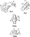
- FIG. 5 is a perspective view of the plate 8 according to another embodiment of the invention.
- This plate 8 comprises a head 9, comprising a hole 10 whose diameter corresponds to that of the plate thread.
- the plate further comprises, disposed substantially perpendicular to the head, a groove 14.
- This groove 14 includes a split bore 15, the opening of which corresponds to the diameter of the rod.
- the embodiment shown is that in which the split bore has the shape of an ⁇ (omega), which is "turned over" in the figure.
- FIG. 6a is an enlarged view of a crown 19, when the latter is present, of the screw 1.
- This crown 19 has a flat 20, consisting of a face 20a parallel to the axis of the screw and of a face 20b transverse or perpendicular to the axis of the screw. This flat engages in correspondence in the head of the plate in order to prevent any rotation of the plate around the screw.
- the crown is optional when the tightening means 4 has a profile of 6 flat sides, since in the latter case the clamping means has the flat face 20a.
- FIG. 6b is an enlarged view of the head of the plate which adapts to the crown described in FIG. 6a.
- the head 9 has, in the lower part of the hole 10, also a flat 20 whose flat part corresponds to the face 20a on the flat 21 of the screw 1, or corresponds to one of the flanges of the clamping means 4 when the latter is that shown in Figure la.
- FIG 7 is a perspective view of a fastening means according to an embodiment of the present invention.
- This fixing means is placed on the rod 22 and is called in the following key.
- This key 23 has an internal diameter substantially equal to the diameter of the rod and covers the latter over substantially a quarter of its periphery. An overlap greater than half leading to a slight pinching effect of the key, for example in the case where the key is symmetrical, may however be sought in certain cases.
- the key 23 can rotate around the rod 22, by means of a material which exerts a rotational force by resting on the faces 24a and 24b (hidden in the figure).
- the key is eccentric and has a face 25 having a convex profile and which extends from the face 24a and the face 24b (not shown in the figure).
- This key causes, during its rotation in the bore 15 of the plate, the spacing of the latter and the stress forces block the rod, key and plate in a final position.
- This rotation of the key in the bore is made possible by the convex face 25 of the key which only opposes low friction during rotation. the acute angle formed by the faces 25 and 24b prevents any subsequent rotation of the key.
- Figure 8 is a view of a cross plate according to the present invention.
- This plate 26 has at each of its ends two holes, respectively 26a and 26b, of generally oval shape.
- This plate has a general shape and is made of a material that allows its adaptation to the anatomy of the vertebra.
- Figure 9 is a perspective view of the osteosynthesis system according to the present invention, as mounted on a vertebra and at the stage where the grub screw must be put in place to effect the securing of the system.
- the dotted lines indicate the part of the pedicle screw hidden by the plate or in the vertebral bone.
- the intraosseous pedicle thread is from a length of about 35 to about 45 mm, the diameter varies from about 3.5 to about 5.5 mm for the most cylindrical part. inside the bone and from about 4.5 to about 6.5 mm for the conical part close to the surface of the bone, when the pedicle screw has the profile as described in Figure 1.
- the platinum thread extra-osseous is about 20 mm long, sometimes longer to benefit from a more pronounced lag screw effect, and the diameter varies between about 3.5 and about 5.5 mm.
- the clamping means 4 the flat-sided element represents approximately 5 mm of the length of the plate thread.
- the overall dimensions thereof are, for example: height of approximately 10 mm, width of approximately 10 mm, length of approximately 15 mm.
- the internal diameter thereof is approximately 3 mm, or approximately the diameter of the rod.
- the bore has the shape of an omega, the opening is substantially identical to the diameter of the rod.
- the hole through the head engaging the plate thread is located about 5 mm from the edge of the plate, while the bore is placed about 3.5 mm from the edge of the plate and is made until about half the thickness of the plate.
- the thread in the bore has a diameter of approximately 4 mm and is made from the surface of the plate until the bore is reached.
- the locking screw thus has a thickness of approximately 4 mm.
- the rod has a diameter of about 3 mm and a length between 100 and 400 mm.
- the thickness of the clamping nut is around 4 mm, the lateral grooves having a depth of about 1 mm.
- the dimensions of the transverse plate are standard; for example, the length is between approximately 65 and approximately 75 mm, the width is approximately 8 mm, and the largest dimension of the oval holes is between approximately 25 and approximately 30 mm, the smallest dimension is about 4 mm and the holes are located about 3 mm from the edge of the cross plate.
- the present spinal osteosynthesis system is implemented using ancillary equipment which includes: distraction and compression forceps, rod holder, reduction tubes, screwdriver.
- FIG. 10 illustrates a characteristic element of this material, the reduction tube 27.
- the latter has a distal end 28 which fits on the free end of the plate thread of the screw, possibly on the nut. This distal end has an internal thread 29 which corresponds to the platinum thread.
- a cleaning hole 30 is also provided laterally.
- this tube allows the action of reducing clamps, the jaw of which consists of a concave part which comes to adapt to the reduction tube.
- These reduction clamps are of two types, some allowing compression by their tightening, others allowing distraction.
- the compression clamps can also be adapted on the two screws of the same vertebra and be used for derotation.
- the key-holder pliers have a distal part, the ends of the branches of which have hooks enabling stress to be exerted on the key. Any conventional ancillary equipment can also be used.
- the present osteosynthesis system can be made of any biocompatible material conventionally used in the art of prostheses, orthoses, osteosyntheses and others.
- a material having the required mechanical and biocompatibility qualities non-limiting mention may be made of titanium alloys.
- the material constituting the present osteosysthesis system is an alloy based on titanium, advantageously TA6V.
- the special lag screws that is to say with a longer platinum thread, are placed on the listhesic vertebra. At first, the surgeon distracts the overlying and underlying vertebrae. It is then possible to exert a traction in the axis of the vertebra concerned, either by tightening the nut on the plate after fitting the rod, or using a reducing tube provided with a thread corresponding to that of the platinum thread of the pedicle screw, and subsequent connection of the assembly.
- the pedicle screws are placed on the strategic vertebrae such as L5, the corresponding plates are put in place as well as any transverse plates, on each stage, the assembly is locked using a nut.
- the reduction tubes are placed on each screw and the pliers are then used.
- the surgeon exerts a proximal action of the distraction forceps and there is creation of the intervertebral gap.
- it exerts an action of the compression clamps in transverse position allowing manual derotation.
- it exerts an action of the compression clamps on the distal part of the tubes, thus ensuring lordosis.
- the clamps are then "clamped", the reduction is maintained as well, and the fixing rods can be shaped and placed in the grooves in U (respectively in ⁇ (omega)).
- the grub screws (respectively the keys) are placed on each floor, and locked.
Landscapes
- Health & Medical Sciences (AREA)
- Orthopedic Medicine & Surgery (AREA)
- Life Sciences & Earth Sciences (AREA)
- Surgery (AREA)
- Medical Informatics (AREA)
- Engineering & Computer Science (AREA)
- Biomedical Technology (AREA)
- Heart & Thoracic Surgery (AREA)
- Nuclear Medicine, Radiotherapy & Molecular Imaging (AREA)
- Molecular Biology (AREA)
- Animal Behavior & Ethology (AREA)
- General Health & Medical Sciences (AREA)
- Public Health (AREA)
- Veterinary Medicine (AREA)
- Neurology (AREA)
- Surgical Instruments (AREA)
- Prostheses (AREA)
Applications Claiming Priority (2)
| Application Number | Priority Date | Filing Date | Title |
|---|---|---|---|
| FR9210956 | 1992-09-15 | ||
| FR9210956 | 1992-09-15 |
Publications (2)
| Publication Number | Publication Date |
|---|---|
| EP0593321A1 true EP0593321A1 (de) | 1994-04-20 |
| EP0593321B1 EP0593321B1 (de) | 1999-10-27 |
Family
ID=9433495
Family Applications (1)
| Application Number | Title | Priority Date | Filing Date |
|---|---|---|---|
| EP93402234A Expired - Lifetime EP0593321B1 (de) | 1992-09-15 | 1993-09-14 | Vorrichtung zur Osteosynthese von Rückenwirbeln |
Country Status (3)
| Country | Link |
|---|---|
| US (1) | US5571102A (de) |
| EP (1) | EP0593321B1 (de) |
| DE (1) | DE69326867D1 (de) |
Cited By (2)
| Publication number | Priority date | Publication date | Assignee | Title |
|---|---|---|---|---|
| EP0729731A1 (de) * | 1995-03-03 | 1996-09-04 | Industrias Quirurgicas De Levante, S.A. | System zum Fixieren einer Wirbelsäule |
| WO1999058072A1 (de) * | 1998-05-07 | 1999-11-18 | Synthes Ag Chur | Backe für eine externe knochenfixationsvorrichtung |
Families Citing this family (13)
| Publication number | Priority date | Publication date | Assignee | Title |
|---|---|---|---|---|
| US6123707A (en) * | 1999-01-13 | 2000-09-26 | Spinal Concepts, Inc. | Reduction instrument |
| EP1253854A4 (de) | 1999-03-07 | 2010-01-06 | Discure Ltd | Verfahren und vorrichtung für computerisierte chirurgie |
| EP1184000A1 (de) * | 2000-08-31 | 2002-03-06 | ORTHOFIX S.r.l. | Äusserer Fixateur zur Stabilisierung von Knochenbrüchen |
| US6746449B2 (en) | 2001-09-12 | 2004-06-08 | Spinal Concepts, Inc. | Spinal rod translation instrument |
| SE521943C2 (sv) * | 2002-04-09 | 2003-12-23 | Henrik Hansson | Anordning för utdragning av stift vid fixeringsorgan för fixering av benfragment vid benbrott. |
| US7588575B2 (en) | 2003-10-21 | 2009-09-15 | Innovative Spinal Technologies | Extension for use with stabilization systems for internal structures |
| US7967826B2 (en) | 2003-10-21 | 2011-06-28 | Theken Spine, Llc | Connector transfer tool for internal structure stabilization systems |
| US7588588B2 (en) | 2003-10-21 | 2009-09-15 | Innovative Spinal Technologies | System and method for stabilizing of internal structures |
| US7186255B2 (en) * | 2004-08-12 | 2007-03-06 | Atlas Spine, Inc. | Polyaxial screw |
| US7867255B2 (en) * | 2006-04-07 | 2011-01-11 | Warsaw Orthopedic, Inc. | Spinal rod connector system and method for a bone anchor |
| US8361129B2 (en) | 2006-04-28 | 2013-01-29 | Depuy Spine, Inc. | Large diameter bone anchor assembly |
| US8361123B2 (en) | 2009-10-16 | 2013-01-29 | Depuy Spine, Inc. | Bone anchor assemblies and methods of manufacturing and use thereof |
| US10368919B2 (en) | 2010-07-22 | 2019-08-06 | Globus Medical, Inc. | Sacral-iliac stabilization system |
Citations (7)
| Publication number | Priority date | Publication date | Assignee | Title |
|---|---|---|---|---|
| GB2178323A (en) * | 1985-07-24 | 1987-02-11 | Robert S Howland | Spine fixation system and method |
| FR2615095A1 (fr) * | 1987-05-15 | 1988-11-18 | Fabrication Materiel Orthopedi | Instrumentation d'osteosynthese pour la correction de scolioses lombaires par voie posterieure |
| EP0348581A2 (de) * | 1988-06-10 | 1990-01-03 | Synthes Ag Chur | Implantat zur Fixierung von Wirbeln |
| EP0383992A2 (de) * | 1989-02-08 | 1990-08-29 | Acromed Corporation | Querverbindung für Korrekturvorrichtungen der Wirbelsäule |
| DE3924050A1 (de) * | 1989-07-21 | 1991-01-31 | Hug Gerhard Gmbh | Verbindungselement |
| EP0443894A1 (de) * | 1990-02-19 | 1991-08-28 | Societe De Fabrication De Materiel Orthopedique Sofamor | Osteosynthesevorrichtung zur Berichtigung der Verformungen der Wirbelsäule |
| US5127912A (en) * | 1990-10-05 | 1992-07-07 | R. Charles Ray | Sacral implant system |
Family Cites Families (8)
| Publication number | Priority date | Publication date | Assignee | Title |
|---|---|---|---|---|
| US1529549A (en) * | 1922-03-29 | 1925-03-10 | Richard B Owen | Secondary or storage battery |
| US4648388B1 (en) * | 1985-11-01 | 1995-10-31 | Acromed Corp | Apparatus and method for maintaining vertebrae in a desired relationship |
| US4719905B1 (en) * | 1985-11-01 | 1995-10-31 | Acromed Corp | Apparatus and method for maintaining vertebrae in a desired relationship |
| US4771767A (en) * | 1986-02-03 | 1988-09-20 | Acromed Corporation | Apparatus and method for maintaining vertebrae in a desired relationship |
| US5024213A (en) * | 1989-02-08 | 1991-06-18 | Acromed Corporation | Connector for a corrective device |
| CA2035348C (fr) * | 1990-02-08 | 2000-05-16 | Jean-Louis Vignaud | Dispositif de fixation orientable de tiges d'osteosynthese rachidienne |
| US5129900B1 (en) * | 1990-07-24 | 1998-12-29 | Acromed Corp | Spinal column retaining method and apparatus |
| US5171279A (en) * | 1992-03-17 | 1992-12-15 | Danek Medical | Method for subcutaneous suprafascial pedicular internal fixation |
-
1993
- 1993-09-14 DE DE69326867T patent/DE69326867D1/de not_active Expired - Lifetime
- 1993-09-14 EP EP93402234A patent/EP0593321B1/de not_active Expired - Lifetime
-
1995
- 1995-07-24 US US08/505,903 patent/US5571102A/en not_active Expired - Lifetime
Patent Citations (7)
| Publication number | Priority date | Publication date | Assignee | Title |
|---|---|---|---|---|
| GB2178323A (en) * | 1985-07-24 | 1987-02-11 | Robert S Howland | Spine fixation system and method |
| FR2615095A1 (fr) * | 1987-05-15 | 1988-11-18 | Fabrication Materiel Orthopedi | Instrumentation d'osteosynthese pour la correction de scolioses lombaires par voie posterieure |
| EP0348581A2 (de) * | 1988-06-10 | 1990-01-03 | Synthes Ag Chur | Implantat zur Fixierung von Wirbeln |
| EP0383992A2 (de) * | 1989-02-08 | 1990-08-29 | Acromed Corporation | Querverbindung für Korrekturvorrichtungen der Wirbelsäule |
| DE3924050A1 (de) * | 1989-07-21 | 1991-01-31 | Hug Gerhard Gmbh | Verbindungselement |
| EP0443894A1 (de) * | 1990-02-19 | 1991-08-28 | Societe De Fabrication De Materiel Orthopedique Sofamor | Osteosynthesevorrichtung zur Berichtigung der Verformungen der Wirbelsäule |
| US5127912A (en) * | 1990-10-05 | 1992-07-07 | R. Charles Ray | Sacral implant system |
Cited By (4)
| Publication number | Priority date | Publication date | Assignee | Title |
|---|---|---|---|---|
| EP0729731A1 (de) * | 1995-03-03 | 1996-09-04 | Industrias Quirurgicas De Levante, S.A. | System zum Fixieren einer Wirbelsäule |
| WO1999058072A1 (de) * | 1998-05-07 | 1999-11-18 | Synthes Ag Chur | Backe für eine externe knochenfixationsvorrichtung |
| US6533785B1 (en) | 1998-05-07 | 2003-03-18 | Synthes (Usa) | Clamp for an external bone fixation device |
| MY119587A (en) * | 1998-05-07 | 2005-06-30 | Synthes Gmbh | A clamp for an external bone fixation device |
Also Published As
| Publication number | Publication date |
|---|---|
| EP0593321B1 (de) | 1999-10-27 |
| US5571102A (en) | 1996-11-05 |
| DE69326867D1 (de) | 1999-12-02 |
Similar Documents
| Publication | Publication Date | Title |
|---|---|---|
| CA2133766C (fr) | Dispositif d'osteosynthese rachidienne | |
| EP1439790B9 (de) | Wirbelsäulenstützvorrichtung, die mit klemmen zusammengesetzt ist | |
| EP0645986B1 (de) | Apparat zur behandlung der wirbelsäule | |
| EP0593321B1 (de) | Vorrichtung zur Osteosynthese von Rückenwirbeln | |
| EP0596788B1 (de) | Osteosynthesevorrichtung zur Wirbelsäulenverfestigung | |
| EP0999796B1 (de) | Implantat, insbesondere knochenplatte für die vordere seite der wirbelsäule | |
| EP1578289B1 (de) | Vorrichtung mit vorderplatte für wirbelsäulenabstützung | |
| EP0631492B1 (de) | Vorrichtung fuer die osteosynthese der wirbelsaeule | |
| EP0128058B1 (de) | Wirbelsäulenhaltevorrichtung | |
| EP0841876B1 (de) | Verbinder zum gebrauch für wirbelsäulenosteosynthese-instrumente zur lenden-, sakral oder iliosakral- befestigung | |
| FR2781359A1 (fr) | Materiel d'osteosynthese rachidienne | |
| WO2000016710A1 (fr) | Dispositif d'osteosynthese rachidienne posterieure | |
| FR2651992A1 (fr) | Implant pour osteosynthese rachidienne dorso-lombaire anterieure destine a la correction de cyphoses. | |
| WO1990009156A1 (fr) | Dispositif d'etaiement du rachis | |
| FR2615095A1 (fr) | Instrumentation d'osteosynthese pour la correction de scolioses lombaires par voie posterieure | |
| FR2687561A1 (fr) | Dispositif de redressement, de fixation, de compression et d'elongation de vertebres cervicales. | |
| FR2720261A1 (fr) | Implant pour dispositif d'ostéosynthèse. | |
| WO1995032675A1 (fr) | Dispositif d'osteosynthese a coapteurs rapportes | |
| FR2734471A1 (fr) | Dispositif d'osteosynthese rachidienne | |
| FR2714287A1 (fr) | Dispositif de stabilisation du rachis. | |
| FR2760629A1 (fr) | Dispositif de liaison occipito-cervical | |
| FR2728455A1 (fr) | Dispositif d'osteosynthese | |
| FR2831419A1 (fr) | Appareil de maintien du rachis a assemblage a rotule | |
| FR2772256A1 (fr) | Systeme d'osteosynthese rachidienne | |
| FR2835733A1 (fr) | Patte pour fixer au moins deux portions d'os l'une par rapport a l'autre |
Legal Events
| Date | Code | Title | Description |
|---|---|---|---|
| PUAI | Public reference made under article 153(3) epc to a published international application that has entered the european phase |
Free format text: ORIGINAL CODE: 0009012 |
|
| AK | Designated contracting states |
Kind code of ref document: A1 Designated state(s): BE DE FR GB IT NL |
|
| 17P | Request for examination filed |
Effective date: 19940307 |
|
| 17Q | First examination report despatched |
Effective date: 19950823 |
|
| GRAG | Despatch of communication of intention to grant |
Free format text: ORIGINAL CODE: EPIDOS AGRA |
|
| GRAG | Despatch of communication of intention to grant |
Free format text: ORIGINAL CODE: EPIDOS AGRA |
|
| GRAH | Despatch of communication of intention to grant a patent |
Free format text: ORIGINAL CODE: EPIDOS IGRA |
|
| RAP1 | Party data changed (applicant data changed or rights of an application transferred) |
Owner name: CLERC, ROBERT Owner name: CAVAGNA, REMI |
|
| GRAH | Despatch of communication of intention to grant a patent |
Free format text: ORIGINAL CODE: EPIDOS IGRA |
|
| GRAA | (expected) grant |
Free format text: ORIGINAL CODE: 0009210 |
|
| AK | Designated contracting states |
Kind code of ref document: B1 Designated state(s): BE DE FR GB IT NL |
|
| PG25 | Lapsed in a contracting state [announced via postgrant information from national office to epo] |
Ref country code: NL Free format text: LAPSE BECAUSE OF FAILURE TO SUBMIT A TRANSLATION OF THE DESCRIPTION OR TO PAY THE FEE WITHIN THE PRESCRIBED TIME-LIMIT Effective date: 19991027 Ref country code: IT Free format text: LAPSE BECAUSE OF FAILURE TO SUBMIT A TRANSLATION OF THE DESCRIPTION OR TO PAY THE FEE WITHIN THE PRE;WARNING: LAPSES OF ITALIAN PATENTS WITH EFFECTIVE DATE BEFORE 2007 MAY HAVE OCCURRED AT ANY TIME BEFORE 2007. THE CORRECT EFFECTIVE DATE MAY BE DIFFERENT FROM THE ONE RECORDED.SCRIBED TIME-LIMIT Effective date: 19991027 Ref country code: GB Free format text: LAPSE BECAUSE OF FAILURE TO SUBMIT A TRANSLATION OF THE DESCRIPTION OR TO PAY THE FEE WITHIN THE PRESCRIBED TIME-LIMIT Effective date: 19991027 |
|
| REF | Corresponds to: |
Ref document number: 69326867 Country of ref document: DE Date of ref document: 19991202 |
|
| PG25 | Lapsed in a contracting state [announced via postgrant information from national office to epo] |
Ref country code: DE Free format text: LAPSE BECAUSE OF FAILURE TO SUBMIT A TRANSLATION OF THE DESCRIPTION OR TO PAY THE FEE WITHIN THE PRESCRIBED TIME-LIMIT Effective date: 20000128 |
|
| NLV1 | Nl: lapsed or annulled due to failure to fulfill the requirements of art. 29p and 29m of the patents act | ||
| GBV | Gb: ep patent (uk) treated as always having been void in accordance with gb section 77(7)/1977 [no translation filed] |
Effective date: 19991027 |
|
| RAP2 | Party data changed (patent owner data changed or rights of a patent transferred) |
Owner name: CLERC, ROBERT |
|
| RIN2 | Information on inventor provided after grant (corrected) |
Free format text: CLERC, ROBERT |
|
| PLBE | No opposition filed within time limit |
Free format text: ORIGINAL CODE: 0009261 |
|
| STAA | Information on the status of an ep patent application or granted ep patent |
Free format text: STATUS: NO OPPOSITION FILED WITHIN TIME LIMIT |
|
| PG25 | Lapsed in a contracting state [announced via postgrant information from national office to epo] |
Ref country code: BE Free format text: LAPSE BECAUSE OF NON-PAYMENT OF DUE FEES Effective date: 20000930 |
|
| 26N | No opposition filed | ||
| BERE | Be: lapsed |
Owner name: CLERC ROBERT Effective date: 20000930 Owner name: CAVAGNA REMI Effective date: 20000930 |
|
| PGFP | Annual fee paid to national office [announced via postgrant information from national office to epo] |
Ref country code: FR Payment date: 20030711 Year of fee payment: 11 |
|
| PG25 | Lapsed in a contracting state [announced via postgrant information from national office to epo] |
Ref country code: FR Free format text: LAPSE BECAUSE OF NON-PAYMENT OF DUE FEES Effective date: 20050531 |
|
| REG | Reference to a national code |
Ref country code: FR Ref legal event code: ST |